CN202982102U - Straight stitching and cutting device and second percussion prevention mechanism thereof - Google Patents
Straight stitching and cutting device and second percussion prevention mechanism thereofDownload PDFInfo
- Publication number
- CN202982102U CN202982102UCN 201220750821CN201220750821UCN202982102UCN 202982102 UCN202982102 UCN 202982102UCN 201220750821CN201220750821CN 201220750821CN 201220750821 UCN201220750821 UCN 201220750821UCN 202982102 UCN202982102 UCN 202982102U
- Authority
- CN
- China
- Prior art keywords
- nail bin
- safety block
- nail
- linear stapling
- projection
- Prior art date
- Legal status (The legal status is an assumption and is not a legal conclusion. Google has not performed a legal analysis and makes no representation as to the accuracy of the status listed.)
- Expired - Lifetime
Links
Images


Landscapes
- Surgical Instruments (AREA)
Abstract
Description
Translated fromChinese技术领域technical field
本实用新型涉及一种手术用器械,尤其是一种直线缝切器的防二次击发机构,属于医疗器械技术领域。The utility model relates to an instrument for surgery, in particular to an anti-secondary firing mechanism of a linear slit cutter, which belongs to the technical field of medical instruments.
背景技术Background technique
外科手术用直线缝切器被广泛用于伤口缝合、内部组织缝合与切割。外科手术发展至今,已经越来越倾向于微创手术。广义来讲,能够减少创伤的手术都称为微创手术,而一般认为的狭义的微创手术是指在内窥镜下进行的手术。内窥镜下的手术一般只需要在病人的身体上开几个小孔,将切除、缝合组织及辅助的器械从小孔中伸入病人体内进行手术。微创手术给病人带来的创伤小,病人可以在很短的时间内恢复,因此微创手术越来越受到人们的重视。Surgical linear suture cutters are widely used for wound suturing, internal tissue suturing and cutting. With the development of surgery, minimally invasive surgery has become more and more popular. In a broad sense, surgery that can reduce trauma is called minimally invasive surgery, and it is generally believed that minimally invasive surgery in a narrow sense refers to surgery performed under an endoscope. The operation under the endoscope generally only needs to open a few small holes on the patient's body, and the excision, suturing tissue and auxiliary instruments are inserted into the patient's body through the small holes for surgery. Minimally invasive surgery brings little trauma to patients, and patients can recover in a short period of time. Therefore, minimally invasive surgery has attracted more and more attention.
美国专利US7753246揭示了一种用于微创手术的直线缝切器,包括一器械本体,所述器械本体包括壳体及一枢轴设于壳体上的击发把手,该壳体内设有一个可相对移动的击发顶杆,所述击发顶杆能推动位于壳体前端的钉头组件进行缝合和切除。具体的,所述钉头组件包括一钉仓架,及一与钉仓架枢轴连接的钉砧。所述钉仓架上可拆卸地设有钉仓,钉仓上设有一组内设有推钉片、吻合钉的置钉孔,一般为4排或6排的置钉孔。所述钉砧在与所述置钉孔相对的位置上设有钉成型槽。所述钉头组件还包括一个可移动地设置在钉头组件的接管内的推刀杆,所述推刀杆的远端固定一工字刀,所述工字刀在前进的过程中将钉仓和钉砧闭合。所述工字刀的远端中心设有刀刃,工字刀在前进的过程中该刀刃将位于钉仓和钉砧间的组织切断。所述工字刀的刀刃两侧设有楔形块,所述工字刀在前进的过程中,工字刀驱动楔形块将推钉片依次推出于钉仓外,进而推钉片将吻合钉推出于钉仓外并订合在组织上。现有技术中,医生完成上述的缝切动作后,首先需要将器械复位,继而更换钉仓,以便缝切器进行下一次的缝切手术。U.S. Patent No. 7,753,246 discloses a linear slit cutter for minimally invasive surgery, including an instrument body, which includes a casing and a firing handle pivotally arranged on the casing. Relative to the moving firing ejector rod, the firing ejector rod can push the nail head assembly located at the front end of the casing to suture and cut off. Specifically, the nail head assembly includes a staple cartridge frame and an anvil pivotally connected to the staple cartridge frame. The staple cartridge rack is detachably provided with a staple cartridge, and the staple cartridge is provided with a set of staple holes provided with pushers and staples, generally 4 or 6 rows of staple holes. The nail anvil is provided with a nail forming groove at a position opposite to the nail setting hole. The nail head assembly also includes a push knife rod which is movably arranged in the connecting pipe of the nail head assembly. The bin and anvil are closed. The center of the far end of the I-shaped knife is provided with a cutting edge, which cuts off the tissue located between the staple bin and the nail anvil during the advancing process of the I-shaped knife. Wedge-shaped blocks are arranged on both sides of the blade of the I-shaped knife. During the advancement of the I-shaped knife, the I-shaped knife drives the wedge-shaped blocks to push the pusher pieces out of the staple bin one by one, and then push the staples out of the staples. Outside the staple cartridge and stapled to the tissue. In the prior art, after the doctor completes the above-mentioned suturing operation, he first needs to reset the instrument, and then replace the staple cartridge, so that the suture cutter can perform the next suture operation.
但是由于一些粗心的医生或者经验不足的医生,会在未更换已击发的钉仓的情况下进行下一次的手术,这样会导致医疗事故的产生,即进行了切除却没有缝合。为了防止此类事故的发生,现有技术提出了防二次击发的理论,即在未更换已击发的钉仓的情况下,击发把手不能被按动。这样,从根本上防止了由于医生误操作而产生的医疗事故。However, due to some careless doctors or inexperienced doctors, the next operation will be performed without changing the fired staple cartridge, which will lead to medical accidents, that is, the resection is performed but there is no suturing. In order to prevent such accidents, the prior art proposes the theory of preventing secondary firing, that is, the firing handle cannot be pressed without replacing the fired staple cartridge. In this way, medical accidents caused by doctor's misoperation are fundamentally prevented.
美国专利US5485947揭示了两种防二次击发机构。第一种机构中,钉仓上设有一个滑槽,该滑槽内可滑动地设有一个弹性片。初始状态时,该弹性片伸出于所述滑槽外并将推刀杆向上顶起,此时位于推刀杆近端的缺口与钉仓上的突起相互分离,确保所述推刀杆可以被推动。当推刀杆向远端移动时,所述推刀杆将弹性片推入至所述滑槽内,该推刀杆的高度下降。当将所述推刀杆复位后,所述突起刚好被卡在推刀杆的缺口内,使所述推刀杆无法再次移动,起到了防二次击发的效果。第二种机构的原理与第一种机构类似,将一枢轴件来代替弹性片。初始状态时,枢轴件将推刀杆抬起,使推刀杆上的缺口避开钉仓上的突起。当将所述推刀杆复位后,枢轴件翻转,使推刀杆的高度下降,所述突起刚好被卡在推刀杆的缺口内,使所述推刀杆无法再次移动,起到了防二次击发的效果。US Patent No. 5,485,947 discloses two anti-secondary firing mechanisms. In the first type of mechanism, a chute is provided on the staple cartridge, and an elastic piece is slidably provided in the chute. In the initial state, the elastic piece protrudes out of the chute and pushes up the pusher rod. At this time, the notch at the proximal end of the pusher rod is separated from the protrusion on the staple cartridge to ensure that the pusher rod can be pushed. When the pusher rod moves to the far end, the pusher rod pushes the elastic piece into the slide groove, and the height of the pusher rod decreases. After the pusher rod is reset, the protrusion is just stuck in the gap of the pusher rod, so that the pusher rod cannot be moved again, which has the effect of preventing secondary firing. The principle of the second mechanism is similar to that of the first mechanism, and a pivot member is used instead of the elastic piece. In the initial state, the pivot member lifts the knife pusher bar so that the notch on the knife pusher bar avoids the protrusion on the staple cartridge. After the pusher rod is reset, the pivot member is overturned, so that the height of the pusher rod is lowered, and the protrusion is just stuck in the gap of the pusher rod, so that the pusher rod cannot move again, which prevents the pusher from moving again. The effect of the second shot.
现有技术中,由于涉及的零部件非常小,且均装配于钉仓内,导致直线缝切器生产和装配困难。In the prior art, since the parts involved are very small and all of them are assembled in the staple cartridge, it is difficult to produce and assemble the linear seam cutter.
实用新型内容Utility model content
本实用新型的目的:提出一种结构简单的直线缝切器的防二次击发机构。The purpose of this utility model is to propose a secondary firing prevention mechanism of a linear slit cutter with a simple structure.
本实用新型的目的,将通过以下技术方案得以实现:The purpose of this utility model will be achieved through the following technical solutions:
一种直线缝切器的防二次击发机构,包括:一钉仓架;所述钉仓架上可拆卸地设有钉仓,所述钉仓上设有若干个内设有推钉片、吻合钉的置钉孔,用于推动所述推钉片的击发块设置于所述钉仓的滑槽内;一与所述钉仓架枢轴连接的钉砧;一位于近端的接管,所述接管内可移动地设置有一推刀杆及置于所述推刀杆远端的切刀,所述推刀杆推动所述击发块移动;所述钉仓架上枢轴设有一用于防二次击发的保险块,当初始状态时,所述保险块被所述钉仓架旋转限位而相对静止,所述保险块设于所述推刀杆和切刀的远端进而限制所述推刀杆和切刀由直线缝切器的近端至远端的移动;当工作状态时,所述保险块被钉仓压迫并解除所述旋转限位,所述推刀杆和切刀由直线缝切器的近端至远端移动时,驱动所述保险块旋转;当所述推刀杆和切刀由直线缝切器的远端至近端移动时,所述保险块被驱动反向旋转并回复到初始状态。An anti-secondary firing mechanism of a linear seam cutter, comprising: a staple magazine frame; the staple magazine frame is detachably provided with a staple magazine, and the staple magazine is provided with several internally provided with pusher pieces, The staple hole of the staple is used to push the firing block of the staple pusher to be arranged in the chute of the staple cartridge; a nail anvil pivotally connected to the staple cartridge frame; a connecting tube at the proximal end, A pusher rod and a cutter placed at the far end of the pusher rod are movably arranged in the connecting pipe, and the pusher rod pushes the firing block to move; The safety block for preventing secondary firing, when in the initial state, the safety block is relatively stationary by the rotation limit of the staple cartridge frame, and the safety block is arranged at the distal end of the pusher rod and the cutter to limit all The movement of the pusher rod and the cutter from the proximal end to the far end of the linear seam cutter; in the working state, the safety block is pressed by the staple bin and releases the rotation limit, and the pusher rod and the cutter When moving from the proximal end to the distal end of the linear seam cutter, the safety block is driven to rotate; when the pusher rod and the cutter move from the distal end to the proximal end of the linear seam cutter, the safety block is driven Reverse the rotation and return to the original state.
优选的,所述保险块包括一枢轴孔,偏离所述枢轴孔的一端垂直其表面凸设有一凸块,所述凸块包括顶面、内侧面、前端面和后端面。Preferably, the safety block includes a pivot hole, and an end deviated from the pivot hole is provided with a protrusion perpendicular to its surface, and the protrusion includes a top surface, an inner side surface, a front end surface and a rear end surface.
优选的,所述凸块的宽度小于等于所述钉仓架的长槽的宽度,且所述凸块的厚度大于所述长槽的深度,以使所述凸块在初始状态时伸入至所述长槽内。Preferably, the width of the protrusion is less than or equal to the width of the long groove of the staple cartridge holder, and the thickness of the protrusion is greater than the depth of the long groove, so that the protrusion extends into the in the long slot.
优选的,当工作状态时,伸入至所述长槽内的凸块的顶面被设置于所述钉仓内的击发块的下表面压迫。Preferably, in the working state, the top surface of the protrusion protruding into the long groove is pressed by the lower surface of the firing block arranged in the staple cartridge.
本实用新型还揭示了一种直线缝切器,包括本体,设置于所述本体远端的钉仓架;所述钉仓架上可拆卸地设有钉仓,所述钉仓上设有若干个内设有推钉片、吻合钉的置钉孔,用于推动所述推钉片的击发块设置于所述钉仓的滑槽内;一与所述钉仓架枢轴连接的钉砧;一位于近端的接管,所述接管内可移动地设置有一推刀杆及置于所述推刀杆远端的切刀,所述推刀杆推动所述击发块移动;所述钉仓架上枢轴设有一用于防二次击发的保险块,所述保险块设于所述推刀杆和切刀的远端,当器械处于初始状态及击发完毕后的状态时,限制所述推刀杆和切刀由直线缝切器的近端至远端的移动。The utility model also discloses a linear slit cutter, which includes a main body, and a staple cartridge frame arranged at the far end of the body; the staple cartridge frame is detachably provided with a staple cartridge, and the staple cartridge is provided with One is provided with a nail pushing piece and a staple hole for staples, and the firing block for pushing the nail pushing piece is arranged in the chute of the nail bin; an anvil pivotally connected with the nail bin frame ; a connecting tube located at the proximal end, in which a push knife rod and a cutting knife placed at the far end of the push knife rod are movably arranged, and the push knife rod pushes the firing block to move; the staple cartridge The pivot on the frame is provided with a safety block for preventing secondary firing, and the safety block is arranged at the far end of the push knife rod and the cutter, and when the instrument is in the initial state and the state after the firing is completed, the safety block restricts the The movement of the pusher bar and the cutting knife from the proximal end to the distal end of the linear seam cutter.
优选的,当器械处于初始状态及击发完毕后的状态时,所述保险块被所述钉仓架旋转限位而相对静止。Preferably, when the instrument is in the initial state and the state after firing, the safety block is limited by the rotation of the staple cartridge frame and is relatively stationary.
优选的,当工作状态时,所述保险块被钉仓压迫并解除所述旋转限位,所述推刀杆和切刀由直线缝切器的近端至远端移动时,驱动所述保险块旋转。Preferably, in the working state, the safety block is pressed by the staple cartridge and the rotation limit is released, and the safety block is driven when the pusher rod and the cutter move from the proximal end to the distal end of the linear seam cutter. Block rotation.
优选的,所述保险块包括一枢轴孔,偏离所述枢轴孔的一端垂直其表面凸设有一凸块,所述凸块包括顶面、内侧面、前端面和后端面。Preferably, the safety block includes a pivot hole, and an end deviated from the pivot hole is provided with a protrusion perpendicular to its surface, and the protrusion includes a top surface, an inner side surface, a front end surface and a rear end surface.
优选的,所述凸块的宽度小于等于所述钉仓架的长槽的宽度,且所述凸块的厚度大于所述长槽的深度,以使所述凸块在初始状态时伸入至所述长槽内。Preferably, the width of the protrusion is less than or equal to the width of the long groove of the staple cartridge holder, and the thickness of the protrusion is greater than the depth of the long groove, so that the protrusion extends into the in the long slot.
优选的,当工作状态时,伸入至所述长槽内的凸块的顶面被设置于所述钉仓内的击发块的下表面压迫。Preferably, in the working state, the top surface of the protrusion protruding into the long groove is pressed by the lower surface of the firing block arranged in the staple cartridge.
本实用新型的有益效果主要体现在:有效防止医生在未更换已击发的钉仓或钉仓安装不到位的情况下闭合器械,避免医疗事故的发生或对正常组织产生伤害,结构简单有效。The beneficial effect of the utility model is mainly reflected in that it can effectively prevent the doctor from closing the device without replacing the fired staple cartridge or the staple cartridge is not properly installed, avoiding medical accidents or causing damage to normal tissues, and the structure is simple and effective.
附图说明Description of drawings
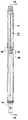
图1是本实用新型优选实施例初始状态保险时的主视图。Fig. 1 is the front view of the preferred embodiment of the utility model when it is insured in the initial state.
图2是图1中沿C-C的剖视图。Fig. 2 is a sectional view along C-C in Fig. 1 .
图3是图1中沿A-A的剖视放大图。Fig. 3 is an enlarged cross-sectional view along A-A in Fig. 1 .
图4是本实用新型优选实施例的设在接管中的钉仓架的立体示意图。Fig. 4 is a three-dimensional schematic view of the magazine rack disposed in the connecting pipe according to the preferred embodiment of the present invention.
图5是本实用新型优选实施例的保险块的立体示意图。Fig. 5 is a schematic perspective view of a safety block in a preferred embodiment of the present invention.
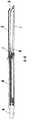
图6是本实用新型优选实施例在工作状态时的主视图。Fig. 6 is a front view of the preferred embodiment of the present invention in working state.
图7是图6中沿D-D的剖视图。Fig. 7 is a sectional view along D-D in Fig. 6 .
图8是图6中B-B的剖视放大图。Fig. 8 is an enlarged cross-sectional view of B-B in Fig. 6 .
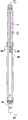
图9是本实用新型优选实施例防二次击发时的主视图。Fig. 9 is a front view of the preferred embodiment of the present invention when preventing secondary firing.
其中:1、钉仓架;11、长槽;12、侧壁;2、钉砧;3、钉仓;4、接管;5、击发块;51、下表面;6、推刀杆;7、切刀;8、保险块;81、枢轴孔;82、凸块;83、顶面;84、内侧面;85、前端面;86、后端面;87、复位部。Among them: 1. Nail bin frame; 11. Long groove; 12. Side wall; 2. Nail anvil; 3. Nail bin; 4. Connector; 5. Firing block; 51. Lower surface; Cutter; 8, safety block; 81, pivot hole; 82, projection; 83, top surface; 84, inner surface; 85, front end surface; 86, rear end surface; 87, reset part.
具体实施方式Detailed ways
本实用新型揭示了一种用于微创手术的直线缝切器,如图1所示,与现有技术一致,包括:一本体,位于本体远端的接管4。所述接管4的远端为钉头组件,包括:一钉仓架1及一与所述钉仓架1枢轴连接的钉砧2。所述钉仓架1上可拆卸地设有钉仓3,所述钉仓3上设有一组内设有推钉片、吻合钉的置钉孔;用于推动所述推钉片的击发块5设置于所述钉仓3的滑槽内。The utility model discloses a linear suturing device for minimally invasive surgery, as shown in Fig. 1, which is consistent with the prior art and includes: a body, and a connecting tube 4 located at the distal end of the body. The distal end of the connecting pipe 4 is a nail head assembly, which includes: a
所述接管4内可移动地设置有一推刀杆6;所述推刀杆6的远端固定一切刀,所述切刀上下设有凸块,呈工字型,所述工字型切刀7在前进的过程中先压迫组织使膨胀的组织变薄和均匀,从而进一步将钉仓3和钉砧2闭合;所述工字刀的远端中心设有刀刃,所述推刀杆6推动切刀7在前进的过程中该刀刃将位于钉仓3和钉砧2间的组织切断,并且所述推刀杆6在前进的过程中推动所述击发块5将推钉片依次推出于钉仓3外,进而推钉片将吻合钉推出于钉仓3外并订合在组织上。A pusher bar 6 is movably arranged in the connecting pipe 4; a cutter is fixed at the far end of the pusher bar 6, and the cutter is provided with bumps up and down, which is I-shaped, and the I-shaped cutter 7. In the process of advancing, the tissue is first pressed to make the expanded tissue thinner and uniform, thereby further closing the
结合图2所示,本实用新型的特点在于:所述钉仓架1上枢轴设有一用于防二次击发的保险块8,所述保险块8设于所述推刀杆6和切刀7的远端,当器械处于初始状态及击发完毕后的状态时,限制所述推刀杆6和切刀7由直线缝切器的近端至远端的移动。As shown in FIG. 2 , the utility model is characterized in that: the upper pivot of the
具体来讲,如图5所示,所述保险块8大致呈片状结构,其包括一用于枢轴连接所述钉仓架1的枢轴孔81,偏离所述枢轴孔81的一端垂直其表面凸设有一凸块82,所述凸块82包括顶面83、内侧面84、前端面85和后端面86。结合图4,所述凸块82的宽度小于等于所述钉仓架1的长槽11的宽度,且所述凸块82的厚度大于所述长槽11的深度,以使所述凸块82在初始状态时伸入至所述长槽11内。所述保险块8上还设有一复位部87,所述复位部87与凸块82分设于枢轴孔81的两侧。所述复位部87呈一倒钩状的片状结构。具体如图1所示,所述保险块8通过枢轴孔81枢轴设于所述钉仓架1的底部。Specifically, as shown in FIG. 5 , the
结合图1至图5所示,当初始状态时,所述保险块8的凸块82伸入至所述长槽11内,所述保险块8的内侧面84被所述长槽11的侧壁12所限位,使所述保险块8不能绕其枢轴旋转。由于所述保险块8设于所述推刀杆6和切刀7的远端,且所述保险块8的凸块82位于所述推刀杆6的移动路线上,即所述凸块82穿过长槽11并伸入到钉仓架1的内部,且其顶面83已经高出于所述钉仓架1内部的底面(图4所示)。这样,所述保险块8就能限制所述推刀杆6和切刀7由直线缝切器的近端至远端的移动。这时,所述保险块8起到一个保险的作用。As shown in FIG. 1 to FIG. 5 , in the initial state, the
如图6至图8所示,当工作状态时,在钉仓架1内安装钉仓3,伸入至所述长槽11内的凸块82的顶面83被设置于所述钉仓3内的击发块5的下表面51压迫。此时,凸块82从长槽11内退出,即所述凸块82的内侧面84与所述长槽11的侧壁12在高度方向有相互错位,因此该保险块8不再受到长槽侧壁的约束进而可以相对于钉仓架1枢轴旋转。当所述推刀杆6和切刀7由直线缝切器的近端至远端移动时,所述推刀杆6驱动所述保险块8的前端面85运动,进而驱动所述保险块8旋转。这时,所述推刀杆6的移动路线上的保险已解除,所述推刀杆6和切刀7即由直线缝切器的近端至远端移动,进而进行缝合和切除。As shown in Fig. 6 to Fig. 8, when in the working state, the
当器械击发完毕后,如图9所示,击发块5停留在所述直线缝切器的远端,所述推刀杆6和切刀7由直线缝切器的远端至近端移动进行复位时,所述保险块8的复位部87会被回退的推刀杆和切刀驱动进而使所述保险块8发生反向旋转,凸块82再次伸入至所述长槽11内,与初始阶段的保险效果一样,所述凸块82会限制所述推刀杆6和切刀7由直线缝切器的近端至远端的移动。这样就达到了防二次击发的目的。After the instrument is fired, as shown in Figure 9, the
本实用新型内所描述的表达位置与方向的词,均是以器械操作者作为参照,靠近操作者的一端为近端,远离操作者的一端为远端。The words expressing position and direction described in the utility model all refer to the operator of the instrument, the end close to the operator is the proximal end, and the end far away from the operator is the distal end.
本实用新型尚有多种实施方式,凡采用等同变换或者等效变换而形成的所有技术方案,均落在本实用新型的保护范围之内。The utility model still has multiple implementation modes, and all technical solutions formed by equivalent transformation or equivalent transformation all fall within the protection scope of the utility model.
Claims (10)
Priority Applications (1)
| Application Number | Priority Date | Filing Date | Title |
|---|---|---|---|
| CN 201220750821CN202982102U (en) | 2012-12-18 | 2012-12-18 | Straight stitching and cutting device and second percussion prevention mechanism thereof |
Applications Claiming Priority (1)
| Application Number | Priority Date | Filing Date | Title |
|---|---|---|---|
| CN 201220750821CN202982102U (en) | 2012-12-18 | 2012-12-18 | Straight stitching and cutting device and second percussion prevention mechanism thereof |
Publications (1)
| Publication Number | Publication Date |
|---|---|
| CN202982102Utrue CN202982102U (en) | 2013-06-12 |
Family
ID=48553337
Family Applications (1)
| Application Number | Title | Priority Date | Filing Date |
|---|---|---|---|
| CN 201220750821Expired - LifetimeCN202982102U (en) | 2012-12-18 | 2012-12-18 | Straight stitching and cutting device and second percussion prevention mechanism thereof |
Country Status (1)
| Country | Link |
|---|---|
| CN (1) | CN202982102U (en) |
Cited By (2)
| Publication number | Priority date | Publication date | Assignee | Title |
|---|---|---|---|---|
| CN103860226A (en)* | 2012-12-18 | 2014-06-18 | 苏州天臣国际医疗科技有限公司 | Linear suturing and excising device and secondary cocking prevention mechanism thereof |
| CN115381511A (en)* | 2021-05-19 | 2022-11-25 | 欣格誉科技(无锡)有限公司 | Trigger mechanism for anastomat |
- 2012
- 2012-12-18CNCN 201220750821patent/CN202982102U/ennot_activeExpired - Lifetime
Cited By (5)
| Publication number | Priority date | Publication date | Assignee | Title |
|---|---|---|---|---|
| CN103860226A (en)* | 2012-12-18 | 2014-06-18 | 苏州天臣国际医疗科技有限公司 | Linear suturing and excising device and secondary cocking prevention mechanism thereof |
| WO2014094571A1 (en)* | 2012-12-18 | 2014-06-26 | 苏州天臣国际医疗科技有限公司 | Elongated surgical stapling device |
| CN103860226B (en)* | 2012-12-18 | 2016-03-09 | 苏州天臣国际医疗科技有限公司 | Linear stapling cutter and anti-secondary firing lock thereof |
| CN115381511A (en)* | 2021-05-19 | 2022-11-25 | 欣格誉科技(无锡)有限公司 | Trigger mechanism for anastomat |
| CN115381511B (en)* | 2021-05-19 | 2024-11-12 | 欣格誉科技(无锡)有限公司 | A firing mechanism for anastomosis device |
Similar Documents
| Publication | Publication Date | Title |
|---|---|---|
| CN103860225B (en) | Linear seam cutting device | |
| CN103860221B (en) | Linear stapling cutter nail-head component | |
| CN103860222B (en) | A kind of straight line stitching instrument cutter sweep | |
| CN103860226B (en) | Linear stapling cutter and anti-secondary firing lock thereof | |
| ES2949098T3 (en) | Stapler Head Assembly and Suturing and Cutting Apparatus for Endoscopic Surgery | |
| CN202982106U (en) | Surgical operating instrument | |
| CN103860223B (en) | The nail-head component of Linear stapling cutter | |
| CN202982103U (en) | Straight-line sewing and cutting device | |
| CN204364049U (en) | A kind of nail-head component and chamber mirror surgical operation seaming and cutting device | |
| CN104490436A (en) | Leftwards bent cutting suture instrument | |
| CN109953786A (en) | Nail cartridge assembly and medical stapler using the same | |
| CN105796145B (en) | A kind of nail-head component and hysteroscope surgical operation seaming and cutting device | |
| CN202982102U (en) | Straight stitching and cutting device and second percussion prevention mechanism thereof | |
| CN202982105U (en) | Nail head assembly of straight stitching and cutting device | |
| CN103860220B (en) | Chamber mirror surgical operation straight line seaming and cutting device | |
| JP2024520530A (en) | Staple cartridge with knife | |
| CN103860224B (en) | Straight line stitching instrument cutter sweep | |
| CN105796144B (en) | A kind of nail-head component and hysteroscope surgical operation seaming and cutting device | |
| CN101869497B (en) | Stitching Instruments | |
| CN204364051U (en) | A kind of nail-head component and chamber mirror surgical operation seaming and cutting device | |
| CN202982104U (en) | Straight stitching and cutting device | |
| CN203074788U (en) | Linear type stitching and cutting machine | |
| CN106175861B (en) | Tissue closing device, tissue closure component and the medical instrument equipped with the tissue closure component | |
| CN211049481U (en) | Anvil and medical stapler including the same | |
| CN203074787U (en) | Straight line suturing and incising device for endoscope surgical operation |
Legal Events
| Date | Code | Title | Description |
|---|---|---|---|
| C14 | Grant of patent or utility model | ||
| GR01 | Patent grant | ||
| AV01 | Patent right actively abandoned | Granted publication date:20130612 Effective date of abandoning:20160309 | |
| AV01 | Patent right actively abandoned | Granted publication date:20130612 Effective date of abandoning:20160309 | |
| C25 | Abandonment of patent right or utility model to avoid double patenting |