CN202948398U - Embedded type intelligent self-protection power supply module of computer - Google Patents
Embedded type intelligent self-protection power supply module of computerDownload PDFInfo
- Publication number
- CN202948398U CN202948398UCN 201220644636CN201220644636UCN202948398UCN 202948398 UCN202948398 UCN 202948398UCN 201220644636CN201220644636CN 201220644636CN 201220644636 UCN201220644636 UCN 201220644636UCN 202948398 UCN202948398 UCN 202948398U
- Authority
- CN
- China
- Prior art keywords
- computer
- power supply
- intelligent self
- battery pack
- conversion module
- Prior art date
- Legal status (The legal status is an assumption and is not a legal conclusion. Google has not performed a legal analysis and makes no representation as to the accuracy of the status listed.)
- Expired - Fee Related
Links
- 238000006243chemical reactionMethods0.000claimsabstractdescription26
- 238000004146energy storageMethods0.000abstractdescription12
- 238000010586diagramMethods0.000description5
- 238000000034methodMethods0.000description4
- 230000008901benefitEffects0.000description2
- 230000007613environmental effectEffects0.000description2
- 238000012986modificationMethods0.000description2
- 230000004048modificationEffects0.000description2
- 230000002093peripheral effectEffects0.000description2
- 230000002159abnormal effectEffects0.000description1
- 239000002253acidSubstances0.000description1
- 230000009286beneficial effectEffects0.000description1
- 230000008859changeEffects0.000description1
- 230000007812deficiencyEffects0.000description1
- 238000007599dischargingMethods0.000description1
- 239000003792electrolyteSubstances0.000description1
- 238000005516engineering processMethods0.000description1
- 230000005669field effectEffects0.000description1
- 229910001385heavy metalInorganic materials0.000description1
- 238000012423maintenanceMethods0.000description1
- 230000010355oscillationEffects0.000description1
- 230000008569processEffects0.000description1
- 239000007787solidSubstances0.000description1
- 238000006467substitution reactionMethods0.000description1
Images

Landscapes
- Dc-Dc Converters (AREA)
Abstract
Translated fromChinese
Description
Translated fromChinese技术领域technical field
本实用新型涉及一种新型延时电源,特别涉及一种计算机内嵌式智能自保护供电模块。The utility model relates to a novel time-delay power supply, in particular to a computer embedded intelligent self-protection power supply module.
背景技术Background technique
日常生活中时有因电力系统的不稳定使得公共电网突然断电而导致电脑直接关闭而来不及存储相关数据,同时也对电脑本身硬件造成极大损害。通常为执行重要工作的计算机配备UPS是个不错的解决方法。而由于传统UPS采用铅蓄电池作为储能元件,虽其价格低廉被广泛应用,但其能量密度相对较低、充电时间长、寿命短、需要定期维护,同时其中重金属元素和电解质会对环境造成极大的破坏。总结说来,传统UPS体积过大不便于携带。作为外设连接在电脑主机外部会占去大量空间。因而需要采用一种高功率密度的储能元件为计算机提供断电延时保护。超级电容电池作为一种高能量密度的新型储能元件,具有储能性能好、功率密度高、充放电速度快、使用温度范围广、可靠性高、使用寿命长,绿色环保等特点,作为一种理想的储能设备,超级电容电池非常适合应用在上述场合。同时超级电容电池以其优良的性能势必在未来储能元件的发展中占有重要的一席之地。In daily life, the instability of the power system sometimes causes the public power grid to suddenly cut off the power, causing the computer to be shut down directly and unable to store relevant data, and it also causes great damage to the hardware of the computer itself. It's often a good idea to have a UPS for a computer that performs critical work. Because the traditional UPS uses lead-acid batteries as energy storage components, although its price is low and widely used, its energy density is relatively low, charging time is long, life is short, and regular maintenance is required. At the same time, heavy metal elements and electrolytes in it will cause serious environmental damage big damage. To sum up, the traditional UPS is too large to be portable. Connecting as a peripheral will take up a lot of space outside the host computer. Therefore, it is necessary to adopt a high power density energy storage element to provide power-off delay protection for the computer. As a new type of energy storage element with high energy density, supercapacitor battery has the characteristics of good energy storage performance, high power density, fast charge and discharge speed, wide temperature range, high reliability, long service life, and environmental protection. An ideal energy storage device, supercapacitor batteries are very suitable for the above occasions. At the same time, supercapacitor batteries are bound to occupy an important place in the development of energy storage components in the future due to their excellent performance.
现有技术中有利用DPS芯片实现脉宽调制的控制,继而采用逆变控制技术将超级电容电池产生的直流电逆变为50HZ恒压恒频的交流电直接向电脑电源供电。这种基于超级电容电池强储能能力的UPS拓扑结构,虽然较好的解决了超级电容电池充电放电控制问题。但从根本上来说并未解决UPS体积大,移动携带不便等问题。同时这种控制方法本质上让电流经过了AC-DC-AC-DC的变化,即220V交流市电经整流后给蓄电池充电,蓄电池直流放电由逆变装置变为交流220V电输入给电脑电源,同时电脑电源工作时亦需经过整流将220V交流电转化为直流电。而在电力电子电路里面,能量利用率相对较低的即为整流部分了,而基于传统UPS工作原理的断电延时系统,其后备电池能量转换效率相对较低,从根本上影响了后备电池供电时间。In the prior art, the DPS chip is used to realize the control of pulse width modulation, and then the inverter control technology is used to invert the direct current generated by the supercapacitor battery into a 50HZ constant voltage and constant frequency alternating current to directly supply power to the computer power supply. This UPS topology based on the strong energy storage capacity of supercapacitor batteries can better solve the problem of supercapacitor battery charging and discharging control. But fundamentally speaking, it has not solved the problems of UPS's large size and inconvenient movement and portability. At the same time, this control method essentially makes the current change through AC-DC-AC-DC, that is, the 220V AC mains is rectified to charge the battery, and the DC discharge of the battery is changed from the inverter device to the AC 220V input to the computer power supply. At the same time, when the computer power supply is working, it also needs to be rectified to convert the 220V alternating current into direct current. In the power electronic circuit, the rectification part has a relatively low energy utilization rate, and the power-off delay system based on the traditional UPS working principle has a relatively low energy conversion efficiency of the backup battery, which fundamentally affects the backup battery. power supply time.
实用新型内容Utility model content
本实用新型为了克服现有技术存在的缺点与不足,提供一种计算机内嵌式智能自保护供电模块。In order to overcome the shortcomings and deficiencies of the prior art, the utility model provides a computer-embedded intelligent self-protection power supply module.
本实用新型所采用的技术方案:The technical scheme adopted in the utility model:
一种计算机内嵌式智能自保护供电模块,包括依次连接的超级电容电池组、通断电切换装置、DC/DC变换模块,所述计算机电源分别与超级电容电池组、计算机主板连接,所述DC/DC变换模块经二极管与计算机主板连接。A computer embedded intelligent self-protection power supply module, including a supercapacitor battery pack connected in sequence, a power on and off switching device, and a DC/DC conversion module, the computer power supply is respectively connected to the supercapacitor battery pack and the computer motherboard, the The DC/DC conversion module is connected with the main board of the computer through the diode.
所述DC/DC变换模块由boost升压电路和buck降压电路构成。The DC/DC conversion module is composed of a boost circuit and a buck circuit.
所述通断电切换装置由相互连接的光耦及固态继电器构成。The on-off switching device is composed of optocouplers and solid-state relays connected to each other.
所述通断电切换装置由计算机主板的PS-ON信号控制。The on-off switching device is controlled by the PS-ON signal of the computer motherboard.
本实用新型的有益效果:The beneficial effects of the utility model:
(1)本实用新型作为电脑电源负载接入电脑机箱中,实现模块内嵌式供电大大减小模块占用体积,携带便利。(1) The utility model is connected to the computer case as a computer power supply load to realize the embedded power supply of the module, which greatly reduces the occupied volume of the module and is convenient to carry.
(2)本实用新型采用超级电容电池组作为储能装置,相较之传统蓄电池,绿色环保,充电迅速,循环使用寿命长,大电流放电能力超强,能量转换效率高,过程损失小,大电流能量循环效率高,漏电流小,功率密度高。(2) The utility model uses a supercapacitor battery pack as an energy storage device. Compared with the traditional storage battery, it is green and environmentally friendly, can be charged quickly, has a long cycle life, has a super large current discharge capacity, high energy conversion efficiency, small process loss, and large The current energy cycle efficiency is high, the leakage current is small, and the power density is high.
(3)本实用新型采用DC/DC变换模块,能量转换效率高,输入宽电压,电流输出稳定,纹波小。(3) The utility model adopts a DC/DC conversion module, which has high energy conversion efficiency, wide input voltage, stable current output and small ripple.
附图说明Description of drawings
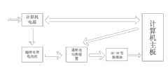
图1为本实用新型的电路结构图,Fig. 1 is a circuit structure diagram of the present utility model,
图2为本实用新型的电路原理图,Fig. 2 is the circuit schematic diagram of the utility model,
图3为本实用新型的DC/DC变换模块中的升压电路原理图,Fig. 3 is a schematic diagram of the boost circuit in the DC/DC conversion module of the present invention,
图4为本实用新型的DC/DC变换模块中的降压电路原理图,Fig. 4 is the schematic diagram of the step-down circuit in the DC/DC conversion module of the present invention,
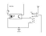
图5为本实用新型的通断电切换装置的电路图。Fig. 5 is a circuit diagram of the on-off switching device of the present invention.
具体实施方式Detailed ways
下面结合实施例及附图,对本实用新型作进一步地详细说明,但本实用新型的实施方式不限于此。The utility model will be described in further detail below in conjunction with the embodiments and accompanying drawings, but the implementation of the utility model is not limited thereto.
实施例Example
如图1所示,一种计算机内嵌式智能自保护供电模块,作为电脑负载接入到电脑机箱中,包括依次连接的超级电容电池组、通断电切换装置、DC/DC变换模块,所述计算机电源分别与超级电容电池组、计算机主板连接,所述DC/DC变换模块经二极管与计算机主板连接。超级电容电池组作为储能器件,实现电源的断电延时功能;DC/DC变换模块将超级电容电池组供给的直流电转化为计算机主板所需的12V,5V,3.3V,-12V等电压,通断电切换装置实现超级电容电池组对DC/DC变换模块供电的截断和导通,所述通断电切换装置由计算机主板的PS-ON信号控制,通过这个信号判断计算机的工作状态。As shown in Figure 1, a computer-embedded intelligent self-protection power supply module is connected to the computer case as a computer load, including a supercapacitor battery pack connected in sequence, a power-on/off switching device, and a DC/DC conversion module. The computer power supply is respectively connected with the supercapacitor battery pack and the computer mainboard, and the DC/DC conversion module is connected with the computer mainboard through a diode. The supercapacitor battery pack is used as an energy storage device to realize the power-off delay function of the power supply; the DC/DC conversion module converts the direct current supplied by the supercapacitor battery pack into 12V, 5V, 3.3V, -12V and other voltages required by the computer motherboard, The on-off switching device realizes the cutoff and conduction of the power supply of the supercapacitor battery pack to the DC/DC conversion module. The on-off switching device is controlled by the PS-ON signal of the computer motherboard, and the working state of the computer is judged by this signal.
如图2所示,计算机电源向计算机主板及各工作系统供电,此时通断电切换装置切断DC/DC变换模块供电电路。同时,计算机电源的+12V输出给超级电容电池组充电。+12V的电压刚好可以满足5节串联超级电容电池充电电压;并且,计算机电源电压输出几乎恒定,电流也相当稳定。如此充分利用电脑电源输出特性给超级电容电池充电,可将二者有机融合起来。由此可删减掉充电电路,使得电路结构更为简单,能量利用率更高。当电网发生故障时,控制线路迅速切换至超级电容电池组供电线路导通模式,超级电容电池组放电,DC/DC变换模块输出对应电压,继续为系统供电。当电网发生故障时,通断电切换装置迅速切换至超级电容电池组供电线路导通模式,超级电容电池组放电,DC/DC变换模块输出电压,继续为计算机主板及各工作系统供电。As shown in FIG. 2 , the computer power supply supplies power to the computer main board and each working system, and at this time, the power on/off switching device cuts off the power supply circuit of the DC/DC conversion module. At the same time, the +12V output of the computer power supply charges the supercapacitor battery pack. The voltage of +12V can just meet the charging voltage of 5 supercapacitor batteries in series; moreover, the computer power supply voltage output is almost constant, and the current is also quite stable. Making full use of the output characteristics of the computer's power supply to charge the supercapacitor battery in this way can organically integrate the two. Thus, the charging circuit can be deleted, so that the circuit structure is simpler and the energy utilization rate is higher. When the power grid fails, the control circuit quickly switches to the conduction mode of the supercapacitor battery pack power supply line, the supercapacitor battery pack is discharged, and the DC/DC conversion module outputs the corresponding voltage to continue supplying power to the system. When the power grid fails, the on-off switching device quickly switches to the conduction mode of the supercapacitor battery pack power supply line, the supercapacitor battery pack discharges, and the DC/DC conversion module outputs voltage to continue to supply power to the computer motherboard and various working systems.
本实用新型作为计算机电源的一个内嵌装置,当市电正常时作为负载储能,当市电异常时,作为输出,以后备电源的形式给系统供电,实现模块可内嵌和自保护供电的功能。The utility model is used as an embedded device of the computer power supply. When the mains power is normal, it is used as a load energy storage. When the mains power is abnormal, it is used as an output to supply power to the system in the form of a backup power supply, so that the module can be embedded and self-protected for power supply. Function.
如图3所示,boost型DC/DC升压电路利用GS3660升压芯片,利用PWM(脉冲宽度调制)的优越性,提供一个高效、较宽电压调节范围的电源。具有较小的静态电流,在重载情况下具有较高的效率,噪声小。采用很小体积的外围元件就可获得满意的输出波形,这样便于降低电路成本及电路的尺寸。该电路PWM输出直接驱动N沟道场效应管驱动升压,宽电压供电2.2V-15V,宽工作频率50KHZ-1MHZ振荡频率,具有欠压保护功能、软启动及短路保护功能。As shown in Figure 3, the boost DC/DC boost circuit uses the GS3660 boost chip to provide a power supply with high efficiency and a wide voltage regulation range by taking advantage of the advantages of PWM (pulse width modulation). It has a small quiescent current, high efficiency under heavy load conditions, and low noise. A satisfactory output waveform can be obtained by using a small volume of peripheral components, which is convenient for reducing circuit cost and circuit size. The PWM output of this circuit directly drives the N-channel field effect transistor to drive the boost, the wide voltage power supply is 2.2V-15V, the wide operating frequency is 50KHZ-1MHZ oscillation frequency, and it has the function of undervoltage protection, soft start and short circuit protection.
如图4所示,buck型DC/DC降压电路利用XL4012降压芯片,输入电压范围可由最低3.6伏特到最高30伏特,输出电压0.8V—23V可调整且输出电流可高达12A内部具有完整的系统保护功能包括可调式软启动、短路保护、过温度保护及可调式过电流保护功能,切换频率固定为260KHz。As shown in Figure 4, the buck type DC/DC step-down circuit uses the XL4012 step-down chip, the input voltage range can be from the lowest 3.6 volts to the highest 30 volts, the output voltage can be adjusted from 0.8V to 23V, and the output current can be as high as 12A. The system protection functions include adjustable soft start, short circuit protection, over temperature protection and adjustable over current protection, and the switching frequency is fixed at 260KHz.
如图5所示,通断电切换装置由光耦和固态继电器构成。固态继电器处于常闭状态。当PS-ON处于高电平状态时(即电脑待机状态),光耦输入端导通,其输出端电阻变小,继电器吸合触点1、3相连,超级电容输出电路处于断开状态。当PS-ON处于低电平状态(电脑开机)光耦输入端未导通,输出端电阻趋于无穷大,继电器保持常闭状态。而由于DC/DC变换模块末端二极管压降,使得DC/DC变换模块输出端电压略低于电脑电源输出端电压。此时DC/DC模块并未工作,但电路中的小电流使得DC/DC变换模块中IC保持待机模式。而当计算机电源断电时,DC/DC变换模块末端二极管迅速导通,DC/DC变换模块开始工作,保证电脑继续工作。As shown in Figure 5, the on-off switching device consists of an optocoupler and a solid-state relay. The solid state relay is normally closed. When the PS-ON is at a high level (that is, the computer is in standby mode), the input terminal of the optocoupler is turned on, the resistance at the output terminal becomes smaller, the pull-in
上述实施例为本实用新型较佳的实施方式,但本实用新型的实施方式并不受所述实施例的限制,其他的任何未背离本实用新型的精神实质与原理下所作的改变、修饰、替代、组合、简化,均应为等效的置换方式,都包含在本实用新型的保护范围之内。The above-mentioned embodiment is a preferred implementation mode of the present utility model, but the implementation mode of the present utility model is not limited by the described embodiment, and any other changes, modifications, modifications, Substitution, combination, and simplification should all be equivalent replacement methods, and are all included in the protection scope of the present utility model.
Claims (4)
Translated fromChinesePriority Applications (1)
| Application Number | Priority Date | Filing Date | Title |
|---|---|---|---|
| CN 201220644636CN202948398U (en) | 2012-11-28 | 2012-11-28 | Embedded type intelligent self-protection power supply module of computer |
Applications Claiming Priority (1)
| Application Number | Priority Date | Filing Date | Title |
|---|---|---|---|
| CN 201220644636CN202948398U (en) | 2012-11-28 | 2012-11-28 | Embedded type intelligent self-protection power supply module of computer |
Publications (1)
| Publication Number | Publication Date |
|---|---|
| CN202948398Utrue CN202948398U (en) | 2013-05-22 |
Family
ID=48424093
Family Applications (1)
| Application Number | Title | Priority Date | Filing Date |
|---|---|---|---|
| CN 201220644636Expired - Fee RelatedCN202948398U (en) | 2012-11-28 | 2012-11-28 | Embedded type intelligent self-protection power supply module of computer |
Country Status (1)
| Country | Link |
|---|---|
| CN (1) | CN202948398U (en) |
Cited By (2)
| Publication number | Priority date | Publication date | Assignee | Title |
|---|---|---|---|---|
| CN102981590A (en)* | 2012-11-28 | 2013-03-20 | 华南理工大学 | Embedded intelligent self-protection power supply module of computer |
| CN109873485A (en)* | 2017-12-05 | 2019-06-11 | 浙江万马新能源有限公司 | A kind of power-down retaining circuit and its control method of automatic switchover |
- 2012
- 2012-11-28CNCN 201220644636patent/CN202948398U/ennot_activeExpired - Fee Related
Cited By (2)
| Publication number | Priority date | Publication date | Assignee | Title |
|---|---|---|---|---|
| CN102981590A (en)* | 2012-11-28 | 2013-03-20 | 华南理工大学 | Embedded intelligent self-protection power supply module of computer |
| CN109873485A (en)* | 2017-12-05 | 2019-06-11 | 浙江万马新能源有限公司 | A kind of power-down retaining circuit and its control method of automatic switchover |
Similar Documents
| Publication | Publication Date | Title |
|---|---|---|
| CN103051042A (en) | Direct current uninterruptible power supply | |
| CN201750208U (en) | Embedded equipment dual power supply automatic switching circuit with backup battery | |
| CN103580272A (en) | Time-delay circuit for outage of power source | |
| CN101685978B (en) | Postpose type backup power system | |
| CN101188361A (en) | An energy management system capable of boosting voltage at a low voltage of 0.3V | |
| CN102968170A (en) | Intelligent self-protection power supply for computer | |
| CN102185358A (en) | Simple and practical movable uninterruptible power supply | |
| CN203522318U (en) | Three-power-supply switching circuit and consumer electronic equipment | |
| CN202948398U (en) | Embedded type intelligent self-protection power supply module of computer | |
| CN206698005U (en) | Dual input double startup exports voltage regulation type uninterrupted switch power supply | |
| CN103529923A (en) | Computer built-in uninterruptible power supply emergency system | |
| CN202995616U (en) | Computer intelligence self-protection power supply power source | |
| CN107154730B (en) | A kind of generation of electricity by new energy two-way changing circuit and control method | |
| CN209282906U (en) | Power circuit and electrical equipment | |
| CN203660640U (en) | Economical power failure maintenance circuit | |
| CN203691031U (en) | Uninterrupted DC power supply | |
| CN203104016U (en) | Power supply circuit of remote controller and air-conditioning system having the same | |
| CN202872443U (en) | Fuel-cell-based communication power supply | |
| CN201994719U (en) | Intelligent power distribution terminal utilizing mixed stored energy | |
| CN201290019Y (en) | Postpositive back-up power system | |
| CN204652285U (en) | A kind of small-sized household solar wind-energy is met an urgent need intelligent power supply | |
| CN202121333U (en) | Standby direct current supply device used for switch | |
| CN102981590A (en) | Embedded intelligent self-protection power supply module of computer | |
| CN202712957U (en) | Power down maintenance circuit of direct current power supply | |
| CN201733125U (en) | Power management system for power comprehensive measurement and control instrument |
Legal Events
| Date | Code | Title | Description |
|---|---|---|---|
| C14 | Grant of patent or utility model | ||
| GR01 | Patent grant | ||
| CF01 | Termination of patent right due to non-payment of annual fee | Granted publication date:20130522 Termination date:20151128 |