CN202931214U - A power conversion device for outputting high voltage electricity - Google Patents
A power conversion device for outputting high voltage electricityDownload PDFInfo
- Publication number
- CN202931214U CN202931214UCN 201220554455CN201220554455UCN202931214UCN 202931214 UCN202931214 UCN 202931214UCN 201220554455CN201220554455CN 201220554455CN 201220554455 UCN201220554455 UCN 201220554455UCN 202931214 UCN202931214 UCN 202931214U
- Authority
- CN
- China
- Prior art keywords
- conversion device
- power conversion
- voltage adjustment
- voltage
- adjustment unit
- Prior art date
- Legal status (The legal status is an assumption and is not a legal conclusion. Google has not performed a legal analysis and makes no representation as to the accuracy of the status listed.)
- Expired - Fee Related
Links
Images


Landscapes
- Rectifiers (AREA)
Abstract
Translated fromChinese
Description
Translated fromChinese技术领域technical field
本实用新型涉及一种转换装置,尤其涉及一种用于输出高压电的电源转换装置。The utility model relates to a conversion device, in particular to a power conversion device for outputting high-voltage electricity.
背景技术Background technique
大量的电子产品需要能输出高压直流电的电源,现有技术通常是将例如市电之类的交流电通过一电源转换装置将其转换为直流电。但现有技术中的电源转换装置主要是先整流,再将整流后的直流电分为多个支路再串联输出的方式,以实现增大输出电压的目的,这种方式虽然可以比较可靠的输出较高的电压,但是由于串联的各个支路输出电压的叠加,各个支路输出电压的纹波也同时叠加到总的输出端,从而增加了输出的直流电中的纹波电压。A large number of electronic products require a power supply capable of outputting high-voltage direct current. In the prior art, alternating current such as commercial power is usually converted into direct current by a power conversion device. However, the power conversion devices in the prior art mainly rectify first, then divide the rectified direct current into multiple branches and then output them in series to achieve the purpose of increasing the output voltage. Although this method can output more reliably Higher voltage, but due to the superposition of the output voltage of each branch in series, the ripple of the output voltage of each branch is also superimposed on the total output terminal at the same time, thereby increasing the ripple voltage in the output DC.
可以理解的是,本部分的陈述仅仅提供与本实用新型相关的背景信息,可能构成或不构成所谓的现有技术。It can be understood that the statements in this section only provide background information related to the present invention, and may or may not constitute so-called prior art.
发明内容Contents of the invention
本实用新型所要解决的技术问题在于针对现有技术中输出高压电的电源转换装置输出的电压中纹波较大的缺陷,提供一种可以减少纹波且能输出高压电的电源转换装置。The technical problem to be solved by the utility model is to provide a power conversion device capable of reducing ripple and outputting high voltage in view of the defects of large ripples in the output voltage of the power conversion device outputting high voltage in the prior art .
本实用新型解决其技术问题所采用的技术方案是提供一种用于输出高压电的电源转换装置,其包括:用于将电源分裂成至少两个支路的分裂变压器、至少两个将分裂变压器输出的交流电转换为直流电的整流单元、及至少两个用于调整上述直流电的电压并抑制直流电中的纹波的电压调整单元;整流单元及电压调整单元的数量与分裂变压器的副级的数量相同,每个整流单元连接于分裂变压器的一个副级与一个电压调整单元之间,且每个电压调整单元依次串联;所述每个电压调整单元包括至少两个并联的BUCK电路;所述电源转换装置还包括用于驱动BUCK电路并使每个电压调整单元中BUCK电路里开关管开始导通的时间相互错开的驱动单元,驱动单元与每个开关管的控制端电连接。The technical solution adopted by the utility model to solve the technical problem is to provide a power conversion device for outputting high-voltage electricity, which includes: a split transformer for splitting the power supply into at least two branches, at least two split transformers A rectification unit that converts the alternating current output by the transformer into direct current, and at least two voltage adjustment units for adjusting the voltage of the above direct current and suppressing the ripple in the direct current; the number of rectification units and voltage adjustment units and the number of secondary stages of the split transformer Same, each rectifier unit is connected between a secondary stage of the split transformer and a voltage adjustment unit, and each voltage adjustment unit is connected in series; each voltage adjustment unit includes at least two parallel BUCK circuits; the power supply The conversion device also includes a driving unit for driving the BUCK circuit and staggering the conduction time of the switching tubes in the BUCK circuits in each voltage adjustment unit, and the driving unit is electrically connected with the control terminal of each switching tube.
在上述电源转换装置中,所述分裂变压器为含有三个副级的三分裂变压器。In the above power conversion device, the split transformer is a three-split transformer including three secondary stages.
在上述电源转换装置中,所述三分裂变压器的每个副级的绕组呈延边三角形结构。In the above power conversion device, the winding of each secondary stage of the three-split transformer is in a triangular structure with extended sides.
在上述电源转换装置中,每个电压调整单元还包括与BUCK电路的输入端并联的第一滤波电容。In the above power conversion device, each voltage adjustment unit further includes a first filter capacitor connected in parallel with the input terminal of the BUCK circuit.
在上述电源转换装置中,每个电压调整单元还包括与BUCK电路的输出端并联的第二滤波电容。In the above power conversion device, each voltage adjustment unit further includes a second filter capacitor connected in parallel with the output terminal of the BUCK circuit.
在上述电源转换装置中,所述电源转换装置的正极或负极输出端连接有电子开关,且电子开关与所述驱动电路电连接。In the above power conversion device, an electronic switch is connected to the positive or negative output end of the power conversion device, and the electronic switch is electrically connected to the driving circuit.
在上述电源转换装置中,所述电子开关为三极管或场效应管。In the above power conversion device, the electronic switch is a triode or a field effect transistor.
在上述电源转换装置中,所述变压器为三相变压器,所述整流单元为三相桥式整流器。In the above power conversion device, the transformer is a three-phase transformer, and the rectification unit is a three-phase bridge rectifier.
本实用新型提供的电源转换装置,其通过分裂变压器、多个整流单元及多个电压调整单元将电源分成多个支路,再将多个电压调整单元串联从而可以输出高压电。同时,电压调整单元包括至少两个并联的BUCK电路,其还包括可以驱动BUCK电路并使每个电压调整单元中BUCK电路里开关管开始导通的时间相互错开的驱动单元,故驱动单元使每个电压调整单元中开关管开始导通的时间不一样,进而使每个电压调整单元中多个BUCK电路错相输出,故每个电压调整单元输出的直流电中纹波相互错开,进而可以大大降低电压调整单元叠加后输出的纹波的幅值。 The power conversion device provided by the utility model divides the power supply into multiple branches by splitting the transformer, multiple rectification units and multiple voltage adjustment units, and then connects the multiple voltage adjustment units in series to output high voltage power. At the same time, the voltage adjustment unit includes at least two parallel BUCK circuits, and it also includes a drive unit that can drive the BUCK circuits and stagger the time when the switch tubes in the BUCK circuits in each voltage adjustment unit start to conduct. The switch tubes in each voltage adjustment unit start to turn on at different times, and then multiple BUCK circuits in each voltage adjustment unit output out of phase, so the ripples in the DC output of each voltage adjustment unit are staggered with each other, which can greatly reduce The amplitude of the ripple output by the voltage adjustment unit after being superimposed. the
附图说明Description of drawings
图1是本实用新型提供的用于输出高压电的电源转换装置的原理框图;Fig. 1 is a functional block diagram of a power conversion device for outputting high-voltage electricity provided by the utility model;
图2是本实用新型提供的一优选实施例的省略显示驱动单元的电源转换装置的结构示意图;Fig. 2 is a schematic structural diagram of a power conversion device omitting a display drive unit according to a preferred embodiment of the present invention;
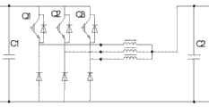
图3是本实用新型提供的一优选实施例中一个电压调整单元的电路原理图;Fig. 3 is a schematic circuit diagram of a voltage adjustment unit in a preferred embodiment provided by the present invention;
图4是采用单路BUCK电路的电压调整单元输出的直流电的电流波形;Fig. 4 is the current waveform of the direct current output by the voltage adjustment unit adopting the single-way BUCK circuit;
图5是本实用新型提供的电源转换装置中电压调整单元采用两路BUCK电路并联且错相后输出的直流电的电流波形。 Fig. 5 is the current waveform of the direct current output after the voltage adjustment unit in the power conversion device provided by the utility model adopts two BUCK circuits connected in parallel and out of phase. the
具体实施方式Detailed ways
为了使本实用新型所解决的技术问题、技术方案及有益效果更加清楚明白,以下结合附图及实施例,对本实用新型进行进一步详细说明。应当理解,此处所描述的具体实施例仅用以解释本实用新型,并不用于限定本实用新型。In order to make the technical problems, technical solutions and beneficial effects solved by the utility model clearer, the utility model will be further described in detail below in conjunction with the accompanying drawings and embodiments. It should be understood that the specific embodiments described here are only used to explain the utility model, and are not intended to limit the utility model.
在本实用新型的描述中,需要理解的是,术语“纵向”、“横向”、“上”、“下”、“前”、“后”、“左”、“右”、“竖直”、“水平”、“顶”、“底”“内”、“外”等指示的方位或位置关系为基于附图所示的方位或位置关系,仅是为了便于描述本实用新型和简化描述,而不是指示或暗示所指的装置或元件必须具有特定的方位、以特定的方位构造和操作,因此不能理解为对本实用新型的限制。In describing the present invention, it should be understood that the terms "longitudinal", "transverse", "upper", "lower", "front", "rear", "left", "right", "vertical" , "horizontal", "top", "bottom", "inner", "outer" and other indicated orientations or positional relationships are based on the orientations or positional relationships shown in the drawings, and are only for the convenience of describing the utility model and simplifying the description. It does not indicate or imply that the device or element referred to must have a specific orientation, be constructed and operate in a specific orientation, and therefore should not be construed as limiting the present invention.
本实用新型提供的电源转换装置主要通过多个BUCK电路错相输出、分裂变压器及驱动BUCK电路里开关管导通时间错开的驱动电路实现减少叠加的纹波的幅值。The power conversion device provided by the utility model mainly realizes reducing the amplitude of superimposed ripples through the out-of-phase output of multiple BUCK circuits, the split transformer and the staggered turn-on time of the switching tubes in the driving BUCK circuits.
参见图1至图5,本实用新型提供的用于输出高压电的电源转换装置,其主要包括:分裂变压器1,用于将电源分裂成至少两个支路的分裂变压器1;至少两个整流单元2,用于将分裂变压器1输出的交流电转换为直流电;至少两个电压调整单元3,用于调整上述直流电的电压并抑制直流电中的纹波;及驱动单元4。整流单元2及电压调整单元3的数量与分裂变压器1的副级的数量相同,每个整流单元2连接于分裂变压器1的一个副级与一个电压调整单元3之间,且每个电压调整单元3依次串联。依次串联的电压调整单元3的两端形成电源转换装置的正极输出端及负极输出端。所以,每个整流单元2将电源的交流电转换为直流电之后,每个电压调整单元3将直流电进行电压调整(例如升压和/或降压),则多个电压调整单元3串联后输出的电压经过叠加后输出高压电。同时,每个电压调整单元3包括至少两个并联的BUCK电路31。每个BUCK电路31里开关管均电连接驱动单元4,以受控于驱动单元4。驱动单元4用于控制BUCK电路31里开关管的导通情况,其决定了开关管开始导通的时间及导通持续的时长。驱动电路使每个电压调整单元3中BUCK电路31里开关管开始导通的时间相互错开,所以每个电压调整单元3中每个BUCK电路31输出的纹波可以实现错相输出,则纹波叠加后的幅值减少。Referring to Fig. 1 to Fig. 5, the power conversion device for outputting high-voltage electricity provided by the utility model mainly includes: a split transformer 1, which is used to split the power supply into at least two branches; at least two The rectifying unit 2 is used to convert the alternating current output by the split transformer 1 into direct current; at least two voltage adjustment units 3 are used to adjust the voltage of the direct current and suppress the ripple in the direct current; and the driving unit 4 . The number of rectification units 2 and voltage adjustment units 3 is the same as the number of sub-stages of the split transformer 1, each rectification unit 2 is connected between a sub-stage of the split transformer 1 and a voltage adjustment unit 3, and each voltage adjustment unit 3 in series in sequence. The two ends of the voltage adjustment units 3 connected in series in sequence form the positive output terminal and the negative output terminal of the power conversion device. Therefore, after each rectifying unit 2 converts the alternating current of the power supply into direct current, each voltage adjusting unit 3 performs voltage adjustment on the direct current (such as step-up and/or step-down), and the output voltage of multiple voltage adjusting units 3 connected in series After superposition, output high voltage electricity. Meanwhile, each voltage adjustment unit 3 includes at least two parallel-connected BUCK circuits 31 . The switch tubes in each BUCK circuit 31 are electrically connected to the driving unit 4 to be controlled by the driving unit 4 . The driving unit 4 is used to control the conduction of the switch in the BUCK circuit 31 , which determines the time when the switch starts to conduct and the duration of the conduction. The drive circuit staggers the time when the switch tubes in the BUCK circuits 31 in each voltage adjustment unit 3 start to turn on, so that the ripple output by each BUCK circuit 31 in each voltage adjustment unit 3 can realize out-of-phase output, and the ripple The amplitude after superimposition is reduced.
再次参见图2及图3所示,在该实施例中,分裂变压器1为三分裂变压器1,其包括有三个副级以将电源输出的交流电分裂成三个支路,且该三分裂变压器1为三相变压器,从而可以应用于三相交流电,例如对市电(图中AC)提供的电源进线转换。下面结合图2对本实用新型提供的电源转换装置的工作原理说明如下:Referring to Fig. 2 and Fig. 3 again, in this embodiment, the split transformer 1 is a three-split transformer 1, which includes three sub-stages to split the AC output of the power supply into three branches, and the three-split transformer 1 It is a three-phase transformer, so it can be applied to three-phase alternating current, such as the conversion of power supply provided by the mains (AC in the figure). Below in conjunction with Fig. 2, the working principle of the power conversion device provided by the utility model is described as follows:
与三分裂变压器1对应的是,电源转换装置中整流单元2为三个,每个整流单元2的输入端接一个副级的输出端,其输出端接一个电压调整单元3的输入端;而且,电源转换装置中电压调整单元3为三个,三个电压调整单元3依次串联。三个电压调整单元3的两端形成电源转换装置的正极输出端及负极输出端,且在其负极输出端电连接有用于控制负载的通断的电子开关。Corresponding to the three-split transformer 1, there are three rectification units 2 in the power conversion device, the input terminal of each rectification unit 2 is connected to the output terminal of a secondary stage, and the output terminal thereof is connected to the input terminal of a voltage adjustment unit 3; and , there are three voltage adjustment units 3 in the power conversion device, and the three voltage adjustment units 3 are connected in series in sequence. The two ends of the three voltage adjustment units 3 form the positive output terminal and the negative output terminal of the power conversion device, and the negative output terminal is electrically connected with an electronic switch for controlling the on-off of the load.
每个电压调整单元3包括三个BUCK电路31且三个BUCK电路31相互并联(3组BUCK电路31的输入端连接在一起,输出端同样连接在一起),而且,BUCK电路31的控制端受控于驱动单元4,以决定BUCK电路31里开关管开始导通的时间。本实用新型提供的驱动单元4(在图2中省略未显示)控制使每个电压调整单元3中BUCK电路31里开关管开始导通的时间相互错开。在图3中,开关管为场效应管,其控制端即其栅极与驱动单元4的输出端连接。例如,驱动单元4使开关管Q1在第1毫秒导通且导通时间为5毫秒,开关管Q2在第10毫秒导通且导通时间为5毫秒,开关管Q3在第30毫秒导通且导通时间为5毫秒。因此,图5中电压调整单元3输出的纹波实现错相输出。参见图4及5所示,图4中 It表示的是采用单路BUCK电路31的电压调整单元3后电源转换装置输出的直流电,图5采样的是两路并联的BUCK电路31形成一电压调节单元,其中,I1和I2分别表示的是两路BUCK电路31输出的直流电,从图可见两路BUCK电路31输出的直流电为错相输出(即存在相位差)。Isum表示两路直流电的电流之和,其有效值与It的有效值相等,从It与Isum的对比可以看到,在电压调整单元3并联及多个BUCK电路31错相输出的情形下,纹波电流频率增加,电流幅值减小,其可以极大的降低对输出滤波器及磁性元件的需求。同时,由于多个电压调整单元3串联,故其叠加后可以输出较宽范围的高压直流电(图中DC)。Each voltage adjustment unit 3 includes three BUCK circuits 31 and the three BUCK circuits 31 are connected in parallel (the input terminals of the three groups of BUCK circuits 31 are connected together, and the output terminals are also connected together), and the control terminals of the BUCK circuits 31 are controlled by It is controlled by the driving unit 4 to determine the time when the switch tube in the BUCK circuit 31 starts to conduct. The driving unit 4 (not shown in FIG. 2 ) provided by the utility model is controlled so that the switching tubes in the BUCK circuit 31 in each voltage adjustment unit 3 start to be turned on and staggered from each other. In FIG. 3 , the switch transistor is a field effect transistor, and its control terminal, that is, its gate, is connected to the output terminal of the drive unit 4 . For example, the drive unit 4 turns on the switch Q1 at the first millisecond and the conduction time is 5 milliseconds, the switch Q2 is turned on at the 10th millisecond and the conduction time is 5 milliseconds, and the switch Q3 is turned on at the 30th millisecond and The on-time is 5 ms. Therefore, the ripple output by the voltage adjustment unit 3 in FIG. 5 realizes out-of-phase output. Referring to Fig. 4 and Fig. 5, what It represents in Fig. 4 is the direct current outputted by the power conversion device after the voltage adjustment unit 3 of the single-way BUCK circuit 31 is adopted, and what Fig. 5 samples is two-way parallel-connected BUCK circuits 31 to form a voltage regulation unit, wherein I1 and I2 represent the direct currents output by the two BUCK circuits 31 respectively, and it can be seen from the figure that the direct currents output by the two BUCK circuits 31 are out-of-phase outputs (that is, there is a phase difference). Isum represents the sum of the currents of two direct currents, and its effective value is equal to the effective value of It. From the comparison between It and Isum, it can be seen that in the case of parallel connection of voltage adjustment units 3 and out-of-phase output of multiple BUCK circuits 31, the ripple The wave current frequency increases and the current amplitude decreases, which can greatly reduce the demand for output filters and magnetic components. At the same time, since multiple voltage adjustment units 3 are connected in series, they can output a wide range of high-voltage direct current (DC in the figure) after being superimposed.
值得说明的是,每个电压调整单元3中开关管导通的持续时间可以相同也可以不同。但是,一个电压调整单元3中多个开关管开始导通的时间存在时间差。优选地,在含有N组BUCK电路31的电压调整单元3中,每个BUCK电路31中开关管的导通时间相同,第N组BUCK电路31里开关管相比较于第1组BUCK电路31里开关管开始导通的时间差为(N-1)/(N*f) ,f指开关管的开关频率,N≥2。It is worth noting that the conduction duration of the switches in each voltage adjustment unit 3 may be the same or different. However, there is a time difference between the times when multiple switch tubes in one voltage adjustment unit 3 start to conduct. Preferably, in the voltage adjustment unit 3 containing N groups of BUCK circuits 31, the conduction time of the switch tubes in each BUCK circuit 31 is the same, and the switch tubes in the Nth group of BUCK circuits 31 are compared with those in the first group of BUCK circuits 31. The time difference when the switch tube starts to conduct is (N-1)/(N*f), where f refers to the switching frequency of the switch tube, and N≥2.
进一步的,分裂变压器1采用存在相位差的结构,即其各个副级的绕组存在相位差。例如图2中,变压器线电压a1b1与a2b2之间的相位差为20度,a1b1与a3b3之间的相位差为40度。其它线电压间的相位差以此类推。所以,优选地,三分裂变压器1的每个副级的绕组呈延边三角形结构,以使其副边存在相位差,进而能实现变压器及电压调整单元3的两极错相输出,故其能更好的抑制纹波。Further, the split transformer 1 adopts a structure with a phase difference, that is, there is a phase difference between the windings of each secondary stage. For example, in Fig. 2, the phase difference between the transformer line voltage a1b1 and a2b2 is 20 degrees, and the phase difference between a1b1 and a3b3 is 40 degrees. The phase difference between other line voltages can be deduced by analogy. Therefore, preferably, the windings of each secondary stage of the three-split transformer 1 have a triangular structure with extended sides, so that there is a phase difference between the secondary sides, so that the two-pole out-of-phase output of the transformer and the voltage adjustment unit 3 can be realized, so it can be better. suppressed ripple.
同时,每个电压调整单元3还包括与BUCK电路31的输入端并联的第一滤波电容C1,每个电压调整单元3还包括与BUCK电路31的输出端并联的第二滤波电容C2,以更好的减少纹波。上述电子开关优选为三极管或场效应管,其能更快的响应驱动单元4的驱动信号,电子开关可以连接于电源转换装置的正极或负极输出端,且其控制端与驱动单元4的输出端电连接,以由驱动单元4根据控制信号决定电子开关的通断。电子开关代替机械式开关,当负载存在短路的情况下,可以有效的切断负载与电源之间的连接。在图3所示优选实施例中,整流单元2为三相桥式整流器,其成本较低,且整流效果较好。三相桥式整流器及驱动单元4的结构为本领域技术人员所熟知,在此不再赘述。At the same time, each voltage adjustment unit 3 also includes a first filter capacitor C1 connected in parallel with the input end of the BUCK circuit 31, and each voltage adjustment unit 3 also includes a second filter capacitor C2 connected in parallel with the output end of the BUCK circuit 31 to further Good for reducing ripple. The above-mentioned electronic switch is preferably a triode or a field effect transistor, which can respond to the drive signal of the drive unit 4 faster, and the electronic switch can be connected to the positive or negative output terminal of the power conversion device, and its control terminal is connected to the output terminal of the drive unit 4. Electrically connected, so that the drive unit 4 determines whether the electronic switch is on or off according to the control signal. The electronic switch replaces the mechanical switch. When the load is short-circuited, it can effectively cut off the connection between the load and the power supply. In the preferred embodiment shown in FIG. 3 , the rectification unit 2 is a three-phase bridge rectifier, which has low cost and good rectification effect. The structures of the three-phase bridge rectifier and the drive unit 4 are well known to those skilled in the art, and will not be repeated here.
综上所述,本实用新型提供的电源转换电路通过电压调整单元的错相输出,可以输出较高直流电,且能大大减少输出的直流电中的纹波。其还可以通过变压器及电压调整单元的两极错相输出,更有效的减少输出电压的纹波。To sum up, the power conversion circuit provided by the utility model can output higher direct current through the out-of-phase output of the voltage adjustment unit, and can greatly reduce the ripple in the output direct current. It can also reduce the ripple of the output voltage more effectively through the two-pole out-of-phase output of the transformer and the voltage adjustment unit.
在本说明书的描述中,参考术语“一个实施例”、“一些实施例”、 “示例”、“具体示例”、或“一些示例”等的描述意指结合该实施例或示例描述的具体特征、结构、材料或者特点包含于本实用新型的至少一个实施例或示例中。在本说明书中,对上述术语的示意性表述不一定指的是相同的实施例或示例。而且,描述的具体特征、结构、材料或者特点可以在任何的一个或多个实施例或示例中以合适的方式结合。In the description of this specification, reference to the terms "one embodiment", "some embodiments", "example", "specific examples", or "some examples" means that specific features described in connection with the embodiment or example , structures, materials or features are included in at least one embodiment or example of the present invention. In this specification, schematic representations of the above terms do not necessarily refer to the same embodiment or example. Furthermore, the specific features, structures, materials or characteristics described may be combined in any suitable manner in any one or more embodiments or examples.
在本实用新型的描述中,除非另有规定和限定,需要说明的是,术语“安装”、“相连”、“连接”应做广义理解,例如,可以是机械连接或电连接,也可以是两个元件内部的连通,可以是直接相连,也可以通过中间媒介间接相连,对于本领域的普通技术人员而言,可以根据具体情况理解上述术语的具体含义。In the description of the present utility model, unless otherwise stipulated and limited, it should be noted that the terms "installation", "connection" and "connection" should be understood in a broad sense, for example, it can be a mechanical connection or an electrical connection, or it can be The internal communication between two elements may be direct connection or indirect connection through an intermediary. Those of ordinary skill in the art can understand the specific meanings of the above terms according to specific situations.
以上所述仅为本实用新型的较佳实施例而已,并不用以限制本实用新型,凡在本实用新型的精神和原则之内所作的任何修改、等同替换和改进等,均应包含在本实用新型的保护范围之内。The above descriptions are only preferred embodiments of the present utility model, and are not intended to limit the present utility model. Any modifications, equivalent replacements and improvements made within the spirit and principles of the present utility model shall be included in this utility model. within the scope of protection of utility models.
Claims (8)
Translated fromChinesePriority Applications (1)
| Application Number | Priority Date | Filing Date | Title |
|---|---|---|---|
| CN 201220554455CN202931214U (en) | 2012-10-26 | 2012-10-26 | A power conversion device for outputting high voltage electricity |
Applications Claiming Priority (1)
| Application Number | Priority Date | Filing Date | Title |
|---|---|---|---|
| CN 201220554455CN202931214U (en) | 2012-10-26 | 2012-10-26 | A power conversion device for outputting high voltage electricity |
Publications (1)
| Publication Number | Publication Date |
|---|---|
| CN202931214Utrue CN202931214U (en) | 2013-05-08 |
Family
ID=48221124
Family Applications (1)
| Application Number | Title | Priority Date | Filing Date |
|---|---|---|---|
| CN 201220554455Expired - Fee RelatedCN202931214U (en) | 2012-10-26 | 2012-10-26 | A power conversion device for outputting high voltage electricity |
Country Status (1)
| Country | Link |
|---|---|
| CN (1) | CN202931214U (en) |
Cited By (3)
| Publication number | Priority date | Publication date | Assignee | Title |
|---|---|---|---|---|
| CN104038070A (en)* | 2014-04-15 | 2014-09-10 | 浙江大学 | Transformer primary side series connection LLC and output parallel connection BUCK two-stage converter |
| CN106300989A (en)* | 2016-09-05 | 2017-01-04 | 南华大学 | High direct voltage high frequency switch power that the variable modulated waveform forward position of a kind of gamut is variable and control method thereof |
| CN113489332A (en)* | 2021-06-30 | 2021-10-08 | 华源智信半导体(深圳)有限公司 | Multiplexed output switching power supply and electronic device |
- 2012
- 2012-10-26CNCN 201220554455patent/CN202931214U/ennot_activeExpired - Fee Related
Cited By (5)
| Publication number | Priority date | Publication date | Assignee | Title |
|---|---|---|---|---|
| CN104038070A (en)* | 2014-04-15 | 2014-09-10 | 浙江大学 | Transformer primary side series connection LLC and output parallel connection BUCK two-stage converter |
| CN104038070B (en)* | 2014-04-15 | 2017-04-19 | 浙江大学 | Transformer primary side series connection LLC and output parallel connection BUCK two-stage converter |
| CN106300989A (en)* | 2016-09-05 | 2017-01-04 | 南华大学 | High direct voltage high frequency switch power that the variable modulated waveform forward position of a kind of gamut is variable and control method thereof |
| CN106300989B (en)* | 2016-09-05 | 2018-11-13 | 南华大学 | A kind of gamut can be changed the variable high direct voltage high frequency switch power in modulated waveform forward position and its control method |
| CN113489332A (en)* | 2021-06-30 | 2021-10-08 | 华源智信半导体(深圳)有限公司 | Multiplexed output switching power supply and electronic device |
Similar Documents
| Publication | Publication Date | Title |
|---|---|---|
| CN107820665B (en) | Power conversion device | |
| US20180269795A1 (en) | Bidirectional resonant conversion circuit and converter | |
| JP6302095B2 (en) | Switching power supply and method for controlling the switching power supply | |
| EP3163734B1 (en) | Dc-dc converter with high transformer ratio | |
| TWI536709B (en) | Power systme and method for providing power | |
| CN111193400B (en) | Power supply device | |
| KR101406476B1 (en) | Bridgeless pfc boost converter | |
| CN109874385B (en) | power conversion system | |
| RU2017102579A (en) | System architecture for a battery charger based on gallium nitride-based power supplies | |
| CN103780099A (en) | A bidirectional DC conversion circuit and switching power supply | |
| CN105932880A (en) | Magnetizing Current Based Control Of Resonant Converters | |
| CN101689809A (en) | Switching power supply device | |
| CN103765754B (en) | There is the invertor of coupling inductance | |
| KR20190115364A (en) | Single and three phase combined charger | |
| CN203617902U (en) | Integrated buck-flyback type high power factor constant current circuit and device | |
| EP3576271A1 (en) | Dc charging system for storage battery of electric vehicle | |
| CN103959629A (en) | Double rectifier for multi-phase contactless energy transfer system | |
| CN107769592B (en) | A Two-Port AC/DC Converter Based on Coupled Inductors | |
| US20190372382A1 (en) | Dc charging system for storage battery of electric vehicle | |
| CN202931214U (en) | A power conversion device for outputting high voltage electricity | |
| CN103986360B (en) | High-frequency isolation type boost type three-level inverter | |
| WO2018123552A1 (en) | Snubber circuit and power conversion system using same | |
| KR101463388B1 (en) | Bidirectional semiconductor transformer using voltage doubler circuit structure | |
| CN102710150B (en) | Synchronous rectification device and synchronous rectification power supply | |
| JP2019041428A (en) | Power supply device and initial charging control method therefor |
Legal Events
| Date | Code | Title | Description |
|---|---|---|---|
| C14 | Grant of patent or utility model | ||
| GR01 | Patent grant | ||
| CF01 | Termination of patent right due to non-payment of annual fee | Granted publication date:20130508 Termination date:20201026 | |
| CF01 | Termination of patent right due to non-payment of annual fee |