CN202930586U - card edge connector - Google Patents
card edge connectorDownload PDFInfo
- Publication number
- CN202930586U CN202930586UCN2012205194809UCN201220519480UCN202930586UCN 202930586 UCN202930586 UCN 202930586UCN 2012205194809 UCN2012205194809 UCN 2012205194809UCN 201220519480 UCN201220519480 UCN 201220519480UCN 202930586 UCN202930586 UCN 202930586U
- Authority
- CN
- China
- Prior art keywords
- terminal
- insulating body
- edge connector
- side wall
- card edge
- Prior art date
- Legal status (The legal status is an assumption and is not a legal conclusion. Google has not performed a legal analysis and makes no representation as to the accuracy of the status listed.)
- Expired - Fee Related
Links
Images


Classifications
- H—ELECTRICITY
- H01—ELECTRIC ELEMENTS
- H01R—ELECTRICALLY-CONDUCTIVE CONNECTIONS; STRUCTURAL ASSOCIATIONS OF A PLURALITY OF MUTUALLY-INSULATED ELECTRICAL CONNECTING ELEMENTS; COUPLING DEVICES; CURRENT COLLECTORS
- H01R12/00—Structural associations of a plurality of mutually-insulated electrical connecting elements, specially adapted for printed circuits, e.g. printed circuit boards [PCB], flat or ribbon cables, or like generally planar structures, e.g. terminal strips, terminal blocks; Coupling devices specially adapted for printed circuits, flat or ribbon cables, or like generally planar structures; Terminals specially adapted for contact with, or insertion into, printed circuits, flat or ribbon cables, or like generally planar structures
- H01R12/70—Coupling devices
- H01R12/71—Coupling devices for rigid printing circuits or like structures
- H01R12/72—Coupling devices for rigid printing circuits or like structures coupling with the edge of the rigid printed circuits or like structures
- H01R12/722—Coupling devices for rigid printing circuits or like structures coupling with the edge of the rigid printed circuits or like structures coupling devices mounted on the edge of the printed circuits
- H01R12/724—Coupling devices for rigid printing circuits or like structures coupling with the edge of the rigid printed circuits or like structures coupling devices mounted on the edge of the printed circuits containing contact members forming a right angle
- H—ELECTRICITY
- H01—ELECTRIC ELEMENTS
- H01R—ELECTRICALLY-CONDUCTIVE CONNECTIONS; STRUCTURAL ASSOCIATIONS OF A PLURALITY OF MUTUALLY-INSULATED ELECTRICAL CONNECTING ELEMENTS; COUPLING DEVICES; CURRENT COLLECTORS
- H01R13/00—Details of coupling devices of the kinds covered by groups H01R12/70 or H01R24/00 - H01R33/00
- H01R13/46—Bases; Cases
- H01R13/514—Bases; Cases composed as a modular blocks or assembly, i.e. composed of co-operating parts provided with contact members or holding contact members between them
Landscapes
- Coupling Device And Connection With Printed Circuit (AREA)
Abstract
Description
Translated fromChinese【技术领域】【Technical field】
本实用新型涉及一种卡缘连接器,尤其涉及一种低构型的卡缘连接器。The utility model relates to a card edge connector, in particular to a low profile card edge connector.
【背景技术】【Background technique】
中国台湾新型专利第M336576号揭露了一种卡缘连接器,可将电子卡电性连接至电路板,该卡缘连接器包括绝缘本体、固持于绝缘本体的导电端子及安装于绝缘本体的固持块,所述导电端子包括上排端子及下排端子,所述导电端子的焊接部穿设于固持块而固定于绝缘本体,所述固持块是自下而上安装于绝缘本体且其底面与绝缘本体的底面平齐。然而,由于导电端子在绝缘本体中呈上下两排设置,绝缘本体必须有足够的高度来容置所述导电端子,如此不利于卡缘连接器的小型化发展。China Taiwan New Patent No. M336576 discloses a card edge connector that can electrically connect an electronic card to a circuit board. block, the conductive terminal includes an upper row of terminals and a lower row of terminals, the welding part of the conductive terminal is passed through the holding block and fixed on the insulating body, the holding block is installed on the insulating body from bottom to top and its bottom surface is in contact with the insulating body The bottom surface of the insulating body is even. However, since the conductive terminals are arranged in two rows up and down in the insulating body, the insulating body must have sufficient height to accommodate the conductive terminals, which is not conducive to the miniaturization of the card edge connector.
所以,希望设计一种新型的卡缘连接器以改善上述问题。Therefore, it is desired to design a new type of card edge connector to improve the above problems.
【实用新型内容】【Content of utility model】
本实用新型所要解决的技术问题在于提供一种低构型的卡缘连接器。The technical problem to be solved by the utility model is to provide a low profile card edge connector.
为解决上述问题,本实用新型卡缘连接器采用如下技术方案:一种卡缘连接器,其包括绝缘本体、固持于绝缘本体上的第一端子及第二端子,所述绝缘本体具有前端面、后端面、自前端面向后凹设的电子卡插槽、位于电子卡插槽两侧的第一侧壁及第二侧壁,第一端子包括固定于第一侧壁的固定部及凸伸至电子卡插槽的接触部,所述卡缘连接器还包括端子模块,第二端子包括接触部及固持于端子模块的固持部,所述端子模块安装于绝缘本体,第二端子的接触部凸伸入电子卡插槽并排列于绝缘本体的第二侧壁。In order to solve the above problems, the card edge connector of the present invention adopts the following technical solution: a card edge connector, which includes an insulating body, a first terminal and a second terminal held on the insulating body, and the insulating body has a front end surface , the rear end surface, the electronic card slot recessed from the front end, the first side wall and the second side wall located on both sides of the electronic card slot, the first terminal includes a fixing part fixed on the first side wall and a protrusion To the contact part of the electronic card slot, the card edge connector also includes a terminal module, the second terminal includes a contact part and a holding part fixed to the terminal module, the terminal module is installed on the insulating body, and the contact part of the second terminal protruding into the slot of the electronic card and arranged on the second side wall of the insulating body.
与现有技术相比,本实用新型具有如下有益效果:第二端子与端子模块注塑成型后组装于绝缘本体的前方,降低了卡缘连接器的高度。Compared with the prior art, the utility model has the following beneficial effects: the second terminal and the terminal module are assembled in front of the insulating body after injection molding, thereby reducing the height of the card edge connector.
【附图说明】【Description of drawings】
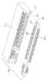
图1是本实用新型卡缘连接器的立体分解图;Fig. 1 is a three-dimensional exploded view of the card edge connector of the present invention;
图2是图1所示卡缘连接器的部分立体分解图;Fig. 2 is a partial perspective exploded view of the card edge connector shown in Fig. 1;
图3是图1所示卡缘连接器的立体图;Fig. 3 is a perspective view of the card edge connector shown in Fig. 1;
图4是沿图3所示A-A线的剖视图。Fig. 4 is a cross-sectional view along line A-A shown in Fig. 3 .
【具体实施方式】【Detailed ways】
请参阅图1及图2,本实用新型卡缘连接器100主要包括绝缘本体1、固持于绝缘本体上的导电端子及组装于绝缘本体1的端子模块3。导电端子包括位于绝缘本体1上侧的第一端子21及与端子模块3注塑成型的第二端子22。Please refer to FIG. 1 and FIG. 2 , the
所述绝缘本体1呈纵长设置,其具有前端面101、后端面、自前端面101向后凹设的电子卡插槽103及位于电子卡插槽103上、下侧的第一侧壁104及第二侧壁105。所述第一侧壁104及第二侧壁105分别设有开口相对设置的端子槽106,第一侧壁104上的端子槽106与第二侧壁105上的端子槽106在纵长方向上彼此偏移一定距离。所述前端面101进一步设有两个安装孔107,所述安装孔107分别设于端子槽106两侧且临近第二侧壁105处。The
所述第一端子21自绝缘本体1的后端面组装于第一侧壁104,其包括固定于第一侧壁104的固定部213、向下凸伸至电子卡插槽103的接触部211及延伸出绝缘本体1的后端面的电路板连接部212,所述电路板连接部212水平排设于电路板(未图示)上(结合图4)。The
请参图2及图4,第二端子22首先与端子模块3注塑成型,第二端子22包括固持于端子模块3中的固持部223、延伸出端子模块3的前侧面的电路板连接部222及延伸出端子模块3的后侧面的接触部221。成型后的端子模块3自基部10的前端面101活动地安装于绝缘本体1的前方并与第二侧壁105位于同一平面,第二端子22的接触部221收容在第二侧壁105的端子槽106内并向上凸伸至电子卡插槽103。该端子模块3的后侧面对应第二侧壁105上的安装孔107设有安装部32。所述每一安装部32分别由两个间隔的倒勾321组成,所述倒勾321勾于安装孔107内。在垂直于电路板连接部222的方向(即高度方向)上,安装部32低于第二端子22的接触部221,安装孔107的高度大于安装部32的高度。在降低卡缘连接器高度的同时,通过端子模块3相对于绝缘本体1作上下方向上的移动,而调整第二端子22的电路板连接部222,以使第二端子22的电路板连接部222与第一端子21的电路板连接部212位于同一平面。Please refer to FIG. 2 and FIG. 4 , the
请参阅图3,由于第二端子22是与端子模块3一体成型后组装于绝缘本体1,因此只需在第二侧壁105设置收容第二端子22的接触部221的端子槽106,相对于现有技术中设置的需收容整个第二端子22的收容槽106而言,本实施方式中的端子槽106对卡缘连接器的强度的影响明显降低,因此占用的卡缘连接器的高度明显降低。同时,由于端子模块3是位于绝缘本体1的前方,而不占用在高度方向上的空间,因此卡缘连接器的高度又得以降低。Please refer to FIG. 3 , since the
由于端子模块3上设置的安装部32的高度小于绝缘本体1上设置的安装孔107的高度,当安装部勾于安装孔107后,安装部32可在安装孔107中上下移动,使得一体成型于端子模块3中的第二端子22的电路板连接部222在电路板(未图示)上作调整进而与第一端子21的电路板连接部212位于同一平面,从而有利于卡缘连接器的共面度。Since the height of the
本实施方式为本实用新型较佳实施方式,当然,本实用新型也可采用其他实时方式,此处不再一一赘述。This implementation mode is a preferred implementation mode of the utility model. Of course, the utility model can also adopt other real-time modes, which will not be repeated here.
Claims (10)
Translated fromChinesePriority Applications (2)
| Application Number | Priority Date | Filing Date | Title |
|---|---|---|---|
| CN2012205194809UCN202930586U (en) | 2012-10-11 | 2012-10-11 | card edge connector |
| US14/052,613US9118154B2 (en) | 2012-10-11 | 2013-10-11 | Miniaturized card edge connector with assembled terminal module |
Applications Claiming Priority (1)
| Application Number | Priority Date | Filing Date | Title |
|---|---|---|---|
| CN2012205194809UCN202930586U (en) | 2012-10-11 | 2012-10-11 | card edge connector |
Publications (1)
| Publication Number | Publication Date |
|---|---|
| CN202930586Utrue CN202930586U (en) | 2013-05-08 |
Family
ID=48220504
Family Applications (1)
| Application Number | Title | Priority Date | Filing Date |
|---|---|---|---|
| CN2012205194809UExpired - Fee RelatedCN202930586U (en) | 2012-10-11 | 2012-10-11 | card edge connector |
Country Status (2)
| Country | Link |
|---|---|
| US (1) | US9118154B2 (en) |
| CN (1) | CN202930586U (en) |
Families Citing this family (2)
| Publication number | Priority date | Publication date | Assignee | Title |
|---|---|---|---|---|
| CN203367548U (en)* | 2013-04-22 | 2013-12-25 | 富士康(昆山)电脑接插件有限公司 | Card edge connector |
| CN107768889A (en) | 2016-08-18 | 2018-03-06 | 富士康(昆山)电脑接插件有限公司 | Electric connector |
Family Cites Families (4)
| Publication number | Priority date | Publication date | Assignee | Title |
|---|---|---|---|---|
| US6666702B1 (en)* | 2002-09-30 | 2003-12-23 | Hon Hai Precision Ind. Co., Ltd. | Electrical connector with matching differential impedance |
| TWM336576U (en) | 2008-02-05 | 2008-07-11 | Bellwether Electronic Corp | Electric connector |
| CN102832479A (en)* | 2011-06-16 | 2012-12-19 | 富士康(昆山)电脑接插件有限公司 | Electrical connector |
| US8894438B2 (en)* | 2012-07-11 | 2014-11-25 | Tyco Electronics Corporation | Receptacle assembly having angled receptacle guide frames |
- 2012
- 2012-10-11CNCN2012205194809Upatent/CN202930586U/ennot_activeExpired - Fee Related
- 2013
- 2013-10-11USUS14/052,613patent/US9118154B2/ennot_activeExpired - Fee Related
Also Published As
| Publication number | Publication date |
|---|---|
| US9118154B2 (en) | 2015-08-25 |
| US20140106622A1 (en) | 2014-04-17 |
Similar Documents
| Publication | Publication Date | Title |
|---|---|---|
| CN201230066Y (en) | Electric connector | |
| CN201029143Y (en) | electrical connector | |
| CN201160177Y (en) | electrical connector | |
| JP3150940U (en) | Electrical connector | |
| CN201252187Y (en) | Card edge connector | |
| CN202076514U (en) | Electric connector | |
| CN2886841Y (en) | Electric connector | |
| CN201252186Y (en) | Card edge connector | |
| CN204696277U (en) | Connector and combination thereof | |
| CN202004174U (en) | Electric connector | |
| CN201608386U (en) | electrical connector | |
| CN203466343U (en) | Electric connector | |
| CN202231194U (en) | Low voltage differential signal (LVDS) connector | |
| CN202930586U (en) | card edge connector | |
| CN201130741Y (en) | Electric Connector | |
| US7654873B2 (en) | Electrical connector provided with alignment slot | |
| CN201383569Y (en) | electrical connector | |
| CN201430318Y (en) | Electric connector | |
| CN204668587U (en) | The improved socket connector of contact engaging and separating force can be strengthened | |
| CN204668603U (en) | The steady type socket connector that contact engaging and separating force strengthens | |
| CN202917667U (en) | Integrated Micro HDMI Electrical Connector Terminal Strip and Micro HDMI Electrical Connector | |
| CN202196955U (en) | Electric connector | |
| CN202076530U (en) | Electric connector | |
| CN2874867Y (en) | Battery connector | |
| CN203503860U (en) | card slot connector |
Legal Events
| Date | Code | Title | Description |
|---|---|---|---|
| C14 | Grant of patent or utility model | ||
| GR01 | Patent grant | ||
| CF01 | Termination of patent right due to non-payment of annual fee | Granted publication date:20130508 Termination date:20171011 | |
| CF01 | Termination of patent right due to non-payment of annual fee |