CN202929338U - A liquid crystal lens module and 3D display device - Google Patents
A liquid crystal lens module and 3D display deviceDownload PDFInfo
- Publication number
- CN202929338U CN202929338UCN2012206618127UCN201220661812UCN202929338UCN 202929338 UCN202929338 UCN 202929338UCN 2012206618127 UCN2012206618127 UCN 2012206618127UCN 201220661812 UCN201220661812 UCN 201220661812UCN 202929338 UCN202929338 UCN 202929338U
- Authority
- CN
- China
- Prior art keywords
- liquid crystal
- lens
- transparent electrode
- display
- crystal lens
- Prior art date
- Legal status (The legal status is an assumption and is not a legal conclusion. Google has not performed a legal analysis and makes no representation as to the accuracy of the status listed.)
- Expired - Fee Related
Links
Images


Landscapes
- Liquid Crystal (AREA)
Abstract
Translated fromChinese
Description
Translated fromChinese技术领域technical field
本实用新型涉及3D显示技术领域,尤其涉及一种液晶透镜模组及3D显示装置。The utility model relates to the technical field of 3D display, in particular to a liquid crystal lens module and a 3D display device.
背景技术Background technique
在日常生活中人们是利用两只眼睛来观察周围具有空间立体感的外界景物的,三维(3D)显示技术就是利用双眼立体视觉原理使人获得三维空间感,其主要原理是使观看者的左眼与右眼分别接收到不同的影像,由观看者两眼之间的瞳距产生的位置差异,使存在“双眼视差”的两副图像构成一对“立体图象对”,而“立体图像对”在经由大脑分析融合后使观看者产生立体感。In daily life, people use two eyes to observe the external scene with a three-dimensional sense of space. Three-dimensional (3D) display technology uses the principle of binocular stereo vision to enable people to obtain a sense of three-dimensional space. The main principle is to make the viewer's left The eye and the right eye receive different images respectively, and the position difference caused by the interpupillary distance between the viewer's two eyes makes the two images with "binocular parallax" constitute a "stereoscopic image pair", while the "stereoscopic image "Right" makes the viewer feel three-dimensional after being analyzed and fused by the brain.
目前,3D显示技术有裸眼式和眼镜式两大类。所谓裸眼式就是通过在显示器上进行特殊的处理,把经过编码处理的3D视频影像独立送入人的左右眼,从而令用户无需借助立体眼镜即可裸眼体验立体感觉。Currently, there are two types of 3D display technologies: glasses-free and glasses-based. The so-called naked-eye type is to send the coded 3D video images to the left and right eyes independently through special processing on the display, so that users can experience the stereoscopic feeling without the help of stereoscopic glasses.
目前,实现裸眼3D显示的显示装置为在诸如液晶显示器(LCD)的光源阵列前方设置光屏障(Barrier)或透镜光栅等遮蔽物,如图1所示,通过透镜光栅可以将显示装置发出的光线汇聚在其焦点上的原理,使左眼像素发出的光射向观看者的左眼,右眼像素发出的光射向观看者的右眼,实现3D显示的效果。At present, a display device that realizes naked-eye 3D display is to set a light barrier (Barrier) or a lens grating in front of a light source array such as a liquid crystal display (LCD). As shown in Figure 1, the light emitted by the display device can The principle of converging on its focal point makes the light emitted by the left-eye pixel shoot to the viewer's left eye, and the light emitted by the right-eye pixel shoots to the viewer's right eye, realizing the effect of 3D display.
为了实现三维显示,现有技术中的一种方案是在显示屏上增加一层液晶透镜,如图2所示,液晶透镜一般是由上基板、下基板、以及在两个基板之间的液晶层组成的,上基板和下基板分别具有条状电极和面电极;在3D显示模式时,通过对不同位置的条状电极通入不同的电压,产生不同的电场强度,使对应的液晶分子发生不同程度的偏转,从而使液晶层产生透镜的效果。In order to realize three-dimensional display, one solution in the prior art is to add a layer of liquid crystal lens on the display screen. The upper substrate and the lower substrate have strip electrodes and surface electrodes respectively; in the 3D display mode, different voltages are applied to the strip electrodes at different positions to generate different electric field strengths, so that the corresponding liquid crystal molecules generate Different degrees of deflection, so that the liquid crystal layer produces the effect of a lens.
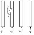
在图2所示的液晶光栅的结构中,当相邻的条状电极之间的具有较大的间隙,例如超过30μm,会造成位于相邻条状电极中间的液晶分子与其他区域的液晶分子取向不一致。并且,在相邻的条状电极之间在通入不同电压的信号时,会在两者之间产生水平电场,影响位于两者之间的液晶分子发生偏转,如图3所示,虚线所示为正常的液晶分子取向方向,由于V1和V2之间产生的水平电场,实线所示的液晶分子会发生微小的偏转。这些取向不一致的液晶分子会造成液晶透镜的串扰问题,即显示装置的右眼像素发出的光,会因液晶分子的不正常取向,射向观看者的左眼;显示装置的左眼像素发出的光,会因液晶分子的不正常取向,射向观看者的右眼,影响3D的显示效果。In the structure of the liquid crystal grating shown in Figure 2, when there is a large gap between adjacent strip electrodes, for example, more than 30 μm, the liquid crystal molecules in the middle of the adjacent strip electrodes will be separated from the liquid crystal molecules in other regions. Inconsistent orientation. Moreover, when signals of different voltages are passed between adjacent strip electrodes, a horizontal electric field will be generated between them, which will affect the deflection of the liquid crystal molecules located between them, as shown in Figure 3, indicated by the dotted line Shown as the normal alignment direction of liquid crystal molecules, due to the horizontal electric field generated between V1 and V2, the liquid crystal molecules shown by the solid line will be slightly deflected. These liquid crystal molecules with inconsistent orientation will cause the problem of crosstalk of the liquid crystal lens, that is, the light emitted by the right-eye pixel of the display device will be emitted to the left eye of the viewer due to the abnormal orientation of the liquid crystal molecules; the light emitted by the left-eye pixel of the display device Light, due to the abnormal orientation of the liquid crystal molecules, will be emitted to the right eye of the viewer, affecting the 3D display effect.
因此,如何降低液晶透镜3D显示的串扰问题,是本领域技术人员亟需解决的技术问题。Therefore, how to reduce the crosstalk problem of the liquid crystal lens 3D display is a technical problem urgently needed to be solved by those skilled in the art.
实用新型内容Utility model content
本实用新型实施例提供了一种液晶透镜模组及3D显示装置,用以解决现有的液晶光栅3D显示的串扰问题。The embodiment of the utility model provides a liquid crystal lens module and a 3D display device, which are used to solve the crosstalk problem of the existing liquid crystal grating 3D display.
本实用新型实施例提供了一种液晶透镜模组,包括:液晶透镜、位于所述液晶透镜下表面的第一偏光片,以及位于所述液晶透镜上表面的第二偏光片;An embodiment of the present invention provides a liquid crystal lens module, comprising: a liquid crystal lens, a first polarizer located on the lower surface of the liquid crystal lens, and a second polarizer located on the upper surface of the liquid crystal lens;
所述第一偏光片和所述第二偏光片的光透过轴方向相互平行。The light transmission axis directions of the first polarizer and the second polarizer are parallel to each other.
本实用新型实施例还提供了一种3D显示装置,包括:显示器,以及设置在所述显示器上的液晶透镜模组,所述液晶透镜模组为本实用新型实施例提供的上述液晶透镜模组。The embodiment of the utility model also provides a 3D display device, including: a display, and a liquid crystal lens module arranged on the display, the liquid crystal lens module is the above-mentioned liquid crystal lens module provided by the embodiment of the utility model .
本实用新型实施例的有益效果包括:The beneficial effects of the utility model embodiment include:
本实用新型实施例提供的一种液晶透镜模组及3D显示装置,在液晶透镜的上下表面分别设置第一偏光片和第二偏光片,且第一偏光片和第二偏光片的光透过轴方向一致。由于液晶透镜内部的液晶分子取向不一致和水平方向扭曲等问题,透过第一偏光片的偏振光在经过液晶透镜的作用后,会造成一部分偏振光的偏振方向发生变化,而第二偏光片能过滤这部分偏振方向发生变化的偏振光,减少由这部分偏振方向发生变化的偏振光引起的液晶透镜3D显示的串扰问题。In the liquid crystal lens module and the 3D display device provided by the embodiment of the present invention, a first polarizer and a second polarizer are respectively arranged on the upper and lower surfaces of the liquid crystal lens, and the light of the first polarizer and the second polarizer passes through The axes are in the same direction. Due to problems such as inconsistent orientation of liquid crystal molecules inside the liquid crystal lens and distortion in the horizontal direction, after the polarized light passing through the first polarizer passes through the action of the liquid crystal lens, the polarization direction of a part of the polarized light will change, while the second polarizer can The part of the polarized light whose polarization direction changes is filtered to reduce the crosstalk problem of the liquid crystal lens 3D display caused by the part of the polarized light whose polarization direction changes.
附图说明Description of drawings
图1为现有的透镜式3D显示的原理图;FIG. 1 is a schematic diagram of an existing lenticular 3D display;
图2为现有技术中液晶透镜的结构示意图;FIG. 2 is a schematic structural view of a liquid crystal lens in the prior art;
图3为现有技术中的液晶透镜的液晶分子在条状电极之间的取向示意图;3 is a schematic diagram of the orientation of liquid crystal molecules between strip electrodes in a liquid crystal lens in the prior art;
图4为本实用新型实施例提供的液晶透镜模组的结构示意图;FIG. 4 is a schematic structural view of a liquid crystal lens module provided by an embodiment of the present invention;
图5为本实用新型实施例提供的3D显示装置的结构示意图;5 is a schematic structural diagram of a 3D display device provided by an embodiment of the present invention;
图6a-图6b为本实用新型实施例提供的实例一的液晶透镜的结构示意图;Figures 6a-6b are schematic structural views of the liquid crystal lens of Example 1 provided by the embodiment of the present invention;
图7a-图7b为本实用新型实施例提供的实例二的液晶透镜的结构示意图;Fig. 7a-Fig. 7b are the schematic structural diagrams of the liquid crystal lens of Example 2 provided by the embodiment of the present invention;
图8a-图8b为本实用新型实施例提供的实例三的液晶透镜的结构示意图;Fig. 8a-Fig. 8b are the schematic structural diagrams of the liquid crystal lens of Example 3 provided by the embodiment of the present invention;
图9a-图9b为本实用新型实施例提供的实例四的液晶透镜的结构示意图;Figure 9a-Figure 9b is a schematic structural view of the liquid crystal lens of Example 4 provided by the embodiment of the present invention;
图10a-图10b为本实用新型实施例提供的实例五的液晶透镜的结构示意图。10a-10b are structural schematic diagrams of the liquid crystal lens of Example 5 provided by the embodiment of the present utility model.
具体实施方式Detailed ways
下面结合附图,对本实用新型实施例提供的液晶透镜模组及3D显示装置的具体实施方式进行详细地说明。The specific implementation manners of the liquid crystal lens module and the 3D display device provided by the embodiments of the present invention will be described in detail below with reference to the accompanying drawings.
附图中各层厚度和区域大小形状不反映液晶透镜模组的真实比例,目的只是示意说明本实用新型内容。The thickness of each layer and the size and shape of the area in the accompanying drawings do not reflect the real proportion of the liquid crystal lens module, and the purpose is only to illustrate the content of the utility model.
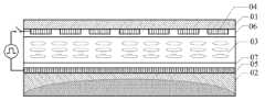
本实用新型实施例提供的液晶透镜模组,如图4所示,具体包括:液晶透镜1、位于液晶透镜1下表面的第一偏光片2,以及位于液晶透镜1上表面的第二偏光片3;The liquid crystal lens module provided by the embodiment of the present invention, as shown in Figure 4, specifically includes: a
第一偏光片2和第二偏光片3的光透过轴方向相互平行。The light transmission axis directions of the
本实用新型实施例提供上述液晶透镜模组,在液晶透镜的上下表面分别设置第一偏光片和第二偏光片,且第一偏光片和第二偏光片的光透过轴方向一致。由于液晶透镜内部的液晶分子取向不一致和水平方向扭曲等问题,透过第一偏光片的偏振光在经过液晶透镜的作用后,会造成一部分偏振光的偏振方向发生变化,而第二偏光片能过滤这部分偏振方向发生变化的偏振光,减少由这部分偏振方向发生变化的偏振光引起的液晶透镜3D显示的串扰问题。The embodiment of the present invention provides the above-mentioned liquid crystal lens module. The first polarizer and the second polarizer are respectively arranged on the upper and lower surfaces of the liquid crystal lens, and the directions of the light transmission axes of the first polarizer and the second polarizer are consistent. Due to problems such as inconsistent orientation of liquid crystal molecules inside the liquid crystal lens and distortion in the horizontal direction, after the polarized light passing through the first polarizer passes through the action of the liquid crystal lens, the polarization direction of a part of the polarized light will change, while the second polarizer can The part of the polarized light whose polarization direction changes is filtered to reduce the crosstalk problem of the liquid crystal lens 3D display caused by the part of the polarized light whose polarization direction changes.
在具体实施时,如图4所示,液晶透镜1一般设置有多个透镜单元4,在3D显示模式时,每个透镜单元4会对透过第一偏光片1的偏振光起透镜作用,将左眼像素发出的光射向观看者的左眼,右眼像素发出的光射向观看者的右眼,实现3D显示的效果。During specific implementation, as shown in FIG. 4 , the
本实用新型实施例还提供了一种3D显示装置,如图5所示,具体包括:显示器5,以及设置在显示器5上的液晶透镜模组6,该液晶透镜模组6为本实用新型实施例提供的上述液晶透镜模组6。The embodiment of the utility model also provides a 3D display device, as shown in Figure 5, specifically comprising: a display 5, and a liquid crystal lens module 6 arranged on the display 5, the liquid crystal lens module 6 is an embodiment of the utility model The above-mentioned liquid crystal lens module 6 provided as an example.
一般地,在显示器5中一个像素单元由三个亚像素组成,例如红、绿、蓝三个亚像素单元,在3D显示模式下,可以在奇数的亚像素列上显示左眼看到的画面,偶数的亚像素列上显示右眼看到的画面;当然也可以以n个亚像素列为一个周期,间隔显示左眼和右眼看到的画面,在此不做具体限定。Generally, a pixel unit in the display 5 is composed of three sub-pixels, such as three sub-pixel units of red, green, and blue. In the 3D display mode, the picture seen by the left eye can be displayed on the odd-numbered sub-pixel columns. Even-numbered sub-pixel rows display images viewed by the right eye; of course, n sub-pixel rows may be used as a period to display images viewed by the left eye and right eye at intervals, which is not specifically limited here.
这样,可以将液晶透镜1中的各透镜单元4与显示器5中相邻的两列亚像素单元对应,其中一列亚像素单元显示左眼图,另一列亚像素单元显示右眼图,例如第一液晶透镜1中的第Ni个透镜单元与显示器5的第i组亚像素单元相对应,就可以将左眼和右眼看到的画面分开,实现3D显示。In this way, each
在具体实施时,上述显示器5可以液晶(LCD)显示面板、有机电致发光(OLED)显示面板、等离子体(PDP)显示面板、或阴极射线(CRT)显示器等,在此不做限定。During specific implementation, the above-mentioned display 5 may be a liquid crystal (LCD) display panel, an organic electroluminescence (OLED) display panel, a plasma (PDP) display panel, or a cathode ray (CRT) display, etc., which are not limited herein.
并且,当3D显示装置应用于LCD显示面板时,由于LCD显示面板中具有偏光片,因此,在液晶透镜模组中可以省去位于液晶透镜下方的第一偏光片,将第二偏光片的光透过轴方向与LCD显示面板中的偏光片的光透过轴方向设置为一致。或者,直接省去LCD显示面板中的偏光片,在此不做限定。Moreover, when the 3D display device is applied to an LCD display panel, since the LCD display panel has a polarizer, the first polarizer located under the liquid crystal lens can be omitted in the liquid crystal lens module, and the light from the second polarizer The transmission axis direction is set to be consistent with the light transmission axis direction of the polarizer in the LCD display panel. Alternatively, the polarizer in the LCD display panel is directly omitted, which is not limited here.
具体地,本实用新型实施例提供的上述液晶透镜模组和3D显示装置中的液晶透镜1可以有多种结构,下面通过具体几个实例对液晶透镜1的具体结构进行举例说明。Specifically, the above-mentioned liquid crystal lens module and the
实例一:液晶透镜1在未加电压时实现2D显示,在加电压后实现3D显示,其具体结构如图6a所示,包括:Example 1: The
上基板01、与上基板01相对设置的下基板02、位于上基板01和下基板02之间的液晶层03、设置于上基板01面向液晶层03一面的第一透明电极04、设置于下基板02面向液晶层03一面的第二透明电极05、设置于第一透明电极04面向液晶层03一面的第一取向膜06、以及设置于第二透明电极05面向液晶层03一面的第二取向膜07。The
在2D显示模式时,第一透明电极04和第二透明电极05未加电压,液晶层03中的液晶沿第一方向平行排列,例如如图6a所示沿平行纸面方向排列,对通过的偏振光无作用。In the 2D display mode, no voltage is applied to the first
具体地,实例一中的第一透明电极04为条状电极,第二透明电极05为面状电极,如图6a所示;或相反,第二透明电极05为条状电极,第一透明电极04为面状电极;Specifically, the first
在3D显示模式时,如图6b所示,对第一透明电极04和第二透明电极05施加电压产生电场,使与每个透镜单元对应的液晶层03中的液晶分子发生偏转,形成凸透镜效果,实现对偏振光进行调制,使其在形成的凸透镜效果的焦点汇聚,在图6b中示出了一个透镜单元中液晶的翻转形状的示意图。In 3D display mode, as shown in Figure 6b, applying a voltage to the first
实例二:液晶透镜1在未加电压时实现3D显示,在加电压后实现2D显示,其具体结构如图7a所示,包括除如图6a和图6b所示的结构之外,还包括:Example 2: The
具有凹透镜结构的透镜层08,该透镜层08可以设置于上基板01和第一透明电极之间,或设置于第一透明电极和第一取向膜之间,图4a中未示出第一透明电极和第一取向膜。A
在2D显示模式时,如图7b所示,对第一透明电极和第二透明电极05施加电压产生电场,使与每个透镜单元对应的液晶层03中的液晶分子发生偏转,形成凸透镜效果,这样形成的凸透镜效果和透镜层08具有的凹透镜结构相互抵消对光的作用,即不会对通过的光线产生作用。In 2D display mode, as shown in Figure 7b, applying a voltage to the first transparent electrode and the second
在3D显示模式时,如图7a所示,第一透明电极和第二透明电极05未加电压,液晶层03中的液晶沿第一方向平行排列,对通过的偏振光无作用,透镜层08对通过的偏振光进行调制,使其在透镜层08的凹透镜结构的焦点汇聚。In the 3D display mode, as shown in Figure 7a, no voltage is applied to the first transparent electrode and the second
实例三:液晶透镜1在未加电压时实现3D显示,在加电压后实现2D显示,其具体结构如图8a所示,包括除如图6a和图6b所示的结构之外,还包括:Example 3: The
具有凸透镜结构的透镜层09,设置于下基板02和第二透明电极之间,或设置于第二透明电极和第二取向膜之间,图8a中未示出第二透明电极和第二取向膜。A lens layer 09 with a convex lens structure is disposed between the
在2D显示模式时,如图8b所示,对第一透明电极04和第二透明电极施加电压产生电场,使与每个透镜单元对应的液晶层03中的液晶分子发生偏转,形成凹透镜效果,这样形成的凹透镜效果和透镜层09具有的凸透镜结构相互抵消对光的作用,即不会对通过的光线产生作用。In 2D display mode, as shown in Figure 8b, applying a voltage to the first
在3D显示模式时,如图8a所示,第一透明电极04和第二透明电极未加电压,液晶层03中的液晶沿第一方向平行排列,对通过的偏振光无作用,透镜层09对通过的偏振光进行调制,使其在透镜层09的凸透镜结构的焦点汇聚。In the 3D display mode, as shown in Figure 8a, no voltage is applied to the first
实施例四:液晶透镜1在未加电压时实现3D显示,在加电压后实现2D显示,其具体结构包括除如图9a和图9b所示的结构之外,还包括:Embodiment 4: The
上基板01背向或朝向液晶层03的任意一面具有凹透镜结构,例如以上基板01背向液晶层03的一面具有凹透镜结构为例,如图9a所示。Any side of the
在2D显示模式时,如图9a所示,对第一透明电极04和第二透明电极06施加电压产生电场,使与每个透镜单元对应的液晶层03中的液晶分子发生偏转,形成凸透镜效果,这样形成的凸透镜效果和上基板01具有的凹透镜结构相互抵消对光的作用,即不会对通过的光线产生作用。In 2D display mode, as shown in Figure 9a, applying a voltage to the first
在3D显示模式时,如图9b所示,第一透明电极04和第二透明电极05未加电压,液晶层03中的液晶沿第一方向平行排列,对通过的偏振光无作用,上基板01具有的凹透镜结构对通过的偏振光进行调制,使其在凹透镜结构的焦点汇聚。In the 3D display mode, as shown in Figure 9b, no voltage is applied to the first
实施例五:液晶透镜1在未加电压时实现3D显示,在加电压后实现2D显示,其具体结构包括除如图6a和图6b所示的结构之外,还包括:Embodiment 5: The
下基板02背向或朝向液晶层03的任意一面具有凸透镜结构;例如以下基板02背向液晶层03的一面具有凸透镜结构为例,如图10a所示。Any side of the
在2D显示模式时,如图10a所示,对第一透明电极04和第二透明电极06施加电压产生电场,使与每个透镜单元对应的液晶层03中的液晶分子发生偏转,形成凹透镜效果,这样形成的凹透镜效果和下基板02具有的凸透镜结构相互抵消对光的作用,即不会对通过的光线产生作用。In 2D display mode, as shown in Figure 10a, applying a voltage to the first
在3D显示模式时,如图10b所示,第一透明电极04和第二透明电极05未加电压,液晶层03中的液晶沿第一方向平行排列,对通过的偏振光无作用,下基板02具有的凸透镜结构对通过的偏振光进行调制,使其在凸透镜结构的焦点汇聚。In the 3D display mode, as shown in Figure 10b, no voltage is applied to the first
本实用新型实施例提供的一种液晶透镜模组及3D显示装置,在液晶透镜的上下表面分别设置第一偏光片和第二偏光片,且第一偏光片和第二偏光片的光透过轴方向一致。由于液晶透镜内部的液晶分子取向不一致和水平方向扭曲等问题,透过第一偏光片的偏振光在经过液晶透镜的作用后,会造成一部分偏振光的偏振方向发生变化,而第二偏光片能过滤这部分偏振方向发生变化的偏振光,减少由这部分偏振方向发生变化的偏振光引起的液晶透镜3D显示的串扰问题。In the liquid crystal lens module and the 3D display device provided by the embodiment of the present invention, a first polarizer and a second polarizer are respectively arranged on the upper and lower surfaces of the liquid crystal lens, and the light of the first polarizer and the second polarizer passes through The axes are in the same direction. Due to problems such as inconsistent orientation of liquid crystal molecules inside the liquid crystal lens and distortion in the horizontal direction, after the polarized light passing through the first polarizer passes through the action of the liquid crystal lens, the polarization direction of a part of the polarized light will change, while the second polarizer can The part of the polarized light whose polarization direction changes is filtered to reduce the crosstalk problem of the liquid crystal lens 3D display caused by the part of the polarized light whose polarization direction changes.
显然,本领域的技术人员可以对本实用新型进行各种改动和变型而不脱离本实用新型的精神和范围。这样,倘若本实用新型的这些修改和变型属于本实用新型权利要求及其等同技术的范围之内,则本实用新型也意图包含这些改动和变型在内。Obviously, those skilled in the art can make various changes and modifications to the utility model without departing from the spirit and scope of the utility model. In this way, if these modifications and variations of the utility model fall within the scope of the claims of the utility model and equivalent technologies thereof, the utility model is also intended to include these modifications and variations.
Claims (11)
Translated fromChinesePriority Applications (1)
| Application Number | Priority Date | Filing Date | Title |
|---|---|---|---|
| CN2012206618127UCN202929338U (en) | 2012-12-04 | 2012-12-04 | A liquid crystal lens module and 3D display device |
Applications Claiming Priority (1)
| Application Number | Priority Date | Filing Date | Title |
|---|---|---|---|
| CN2012206618127UCN202929338U (en) | 2012-12-04 | 2012-12-04 | A liquid crystal lens module and 3D display device |
Publications (1)
| Publication Number | Publication Date |
|---|---|
| CN202929338Utrue CN202929338U (en) | 2013-05-08 |
Family
ID=48219282
Family Applications (1)
| Application Number | Title | Priority Date | Filing Date |
|---|---|---|---|
| CN2012206618127UExpired - Fee RelatedCN202929338U (en) | 2012-12-04 | 2012-12-04 | A liquid crystal lens module and 3D display device |
Country Status (1)
| Country | Link |
|---|---|
| CN (1) | CN202929338U (en) |
Cited By (5)
| Publication number | Priority date | Publication date | Assignee | Title |
|---|---|---|---|---|
| CN104199193A (en)* | 2014-07-31 | 2014-12-10 | 京东方科技集团股份有限公司 | Display device capable of switching 2D display and 3D display |
| WO2015070552A1 (en)* | 2013-11-15 | 2015-05-21 | 合肥京东方光电科技有限公司 | Liquid crystal lens and liquid crystal glasses |
| US10564511B2 (en) | 2013-11-15 | 2020-02-18 | Boe Technology Group Co., Ltd. | Liquid crystal lens and liquid crystal glasses |
| CN110989191A (en)* | 2019-12-20 | 2020-04-10 | 京东方科技集团股份有限公司 | Integrated display panel, manufacturing method thereof and display device |
| CN113031303A (en)* | 2021-04-09 | 2021-06-25 | 京东方科技集团股份有限公司 | Display substrate, control method and display device |
- 2012
- 2012-12-04CNCN2012206618127Upatent/CN202929338U/ennot_activeExpired - Fee Related
Cited By (7)
| Publication number | Priority date | Publication date | Assignee | Title |
|---|---|---|---|---|
| WO2015070552A1 (en)* | 2013-11-15 | 2015-05-21 | 合肥京东方光电科技有限公司 | Liquid crystal lens and liquid crystal glasses |
| US10564511B2 (en) | 2013-11-15 | 2020-02-18 | Boe Technology Group Co., Ltd. | Liquid crystal lens and liquid crystal glasses |
| CN104199193A (en)* | 2014-07-31 | 2014-12-10 | 京东方科技集团股份有限公司 | Display device capable of switching 2D display and 3D display |
| US9838676B2 (en) | 2014-07-31 | 2017-12-05 | Boe Technology Group Co., Ltd. | Three-dimensional display device |
| CN110989191A (en)* | 2019-12-20 | 2020-04-10 | 京东方科技集团股份有限公司 | Integrated display panel, manufacturing method thereof and display device |
| CN110989191B (en)* | 2019-12-20 | 2022-03-04 | 京东方科技集团股份有限公司 | Integrated display panel, manufacturing method thereof and display device |
| CN113031303A (en)* | 2021-04-09 | 2021-06-25 | 京东方科技集团股份有限公司 | Display substrate, control method and display device |
Similar Documents
| Publication | Publication Date | Title |
|---|---|---|
| CN103048841A (en) | Liquid crystal lens module and three-dimensional display device | |
| TWI414846B (en) | 2d and 3d switchable display device and liquid crystal lenticular lens thereof | |
| KR100440956B1 (en) | 2D/3D Convertible Display | |
| US7733296B2 (en) | Driving method of three-dimensional display device | |
| US9772500B2 (en) | Double-layered liquid crystal lens and 3D display apparatus | |
| US9057909B2 (en) | Liquid crystal lens and 3D display device | |
| JP5944616B2 (en) | Optical unit and display device including the same | |
| JP5607430B2 (en) | Stereoscopic display device and electronic device | |
| CN102193204B (en) | Three-dimensional display and three-dimensional display system | |
| JPH01283546A (en) | stereoscopic image display device | |
| CN103676286A (en) | Liquid crystal optical grating panel and device and method for three-dimensional display | |
| CN102830495A (en) | 3D (Three Dimensional) display device | |
| CN103246071A (en) | 3D display device | |
| KR20130055255A (en) | Display device | |
| CN101840071A (en) | Three-dimensional monitor based on liquid crystal lens | |
| CN202929338U (en) | A liquid crystal lens module and 3D display device | |
| CN103048836B (en) | Thin film transistor (TFT) array substrate, liquid crystal display, driving method thereof and three-dimensional (3D) display system | |
| US10151930B2 (en) | Stereoscopic image display device having a barrier cell | |
| TWI399570B (en) | 3d display and 3d display system | |
| US20080169997A1 (en) | Multi-dimensional image selectable display device | |
| CN104656337A (en) | Liquid crystal lens and display device | |
| CN203299500U (en) | Double-layer structure liquid crystal lens and 3D display device | |
| KR101207861B1 (en) | The panel structure and methode of manufacture for stereoscopic lcd | |
| CN202948239U (en) | Liquid crystal lens and 3D (three-dimensional) display device | |
| TWI467536B (en) | Auto stereoscopic display apparatus |
Legal Events
| Date | Code | Title | Description |
|---|---|---|---|
| C14 | Grant of patent or utility model | ||
| GR01 | Patent grant | ||
| CF01 | Termination of patent right due to non-payment of annual fee | Granted publication date:20130508 Termination date:20201204 | |
| CF01 | Termination of patent right due to non-payment of annual fee |