CN202865924U - Intelligent monitoring equipment for household water based on single-point perception - Google Patents
Intelligent monitoring equipment for household water based on single-point perceptionDownload PDFInfo
- Publication number
- CN202865924U CN202865924UCN 201220526520CN201220526520UCN202865924UCN 202865924 UCN202865924 UCN 202865924UCN 201220526520CN201220526520CN 201220526520CN 201220526520 UCN201220526520 UCN 201220526520UCN 202865924 UCN202865924 UCN 202865924U
- Authority
- CN
- China
- Prior art keywords
- water
- pin
- plug
- water pressure
- data acquisition
- Prior art date
- Legal status (The legal status is an assumption and is not a legal conclusion. Google has not performed a legal analysis and makes no representation as to the accuracy of the status listed.)
- Expired - Fee Related
Links
- XLYOFNOQVPJJNP-UHFFFAOYSA-NwaterSubstancesOXLYOFNOQVPJJNP-UHFFFAOYSA-N0.000titleclaimsabstractdescription289
- 230000008447perceptionEffects0.000titleclaimsdescription20
- 238000012544monitoring processMethods0.000titledescription34
- 238000012806monitoring deviceMethods0.000claimsabstractdescription30
- 238000009434installationMethods0.000abstractdescription5
- 238000000034methodMethods0.000description17
- 230000006870functionEffects0.000description12
- 238000004422calculation algorithmMethods0.000description9
- 238000010586diagramMethods0.000description6
- 230000003068static effectEffects0.000description6
- 238000005259measurementMethods0.000description5
- 238000004458analytical methodMethods0.000description4
- 238000004364calculation methodMethods0.000description4
- 239000007788liquidSubstances0.000description4
- 238000012545processingMethods0.000description4
- 238000011156evaluationMethods0.000description3
- 238000011010flushing procedureMethods0.000description3
- 239000007789gasSubstances0.000description3
- 230000001105regulatory effectEffects0.000description3
- 238000013461designMethods0.000description2
- 238000000605extractionMethods0.000description2
- 238000012360testing methodMethods0.000description2
- 238000001363water suppression through gradient tailored excitationMethods0.000description2
- 240000005561Musa balbisianaSpecies0.000description1
- 235000018290Musa x paradisiacaNutrition0.000description1
- 238000013459approachMethods0.000description1
- 230000006399behaviorEffects0.000description1
- 230000009286beneficial effectEffects0.000description1
- 238000009530blood pressure measurementMethods0.000description1
- 238000006243chemical reactionMethods0.000description1
- 239000003086colorantSubstances0.000description1
- 238000013500data storageMethods0.000description1
- 230000007547defectEffects0.000description1
- 238000009795derivationMethods0.000description1
- 238000005516engineering processMethods0.000description1
- 238000002474experimental methodMethods0.000description1
- 239000000284extractSubstances0.000description1
- 238000007689inspectionMethods0.000description1
- WABPQHHGFIMREM-UHFFFAOYSA-Nlead(0)Chemical compound[Pb]WABPQHHGFIMREM-UHFFFAOYSA-N0.000description1
- 238000012423maintenanceMethods0.000description1
- 239000000463materialSubstances0.000description1
- 239000000203mixtureSubstances0.000description1
- 230000009972noncorrosive effectEffects0.000description1
- 239000003921oilSubstances0.000description1
- 230000010355oscillationEffects0.000description1
- 238000003909pattern recognitionMethods0.000description1
- 230000001902propagating effectEffects0.000description1
- 238000011160researchMethods0.000description1
- 239000002699waste materialSubstances0.000description1
Images


Landscapes
- Testing Or Calibration Of Command Recording Devices (AREA)
Abstract
Translated fromChinese
Description
Translated fromChinese技术领域technical field
本实用新型涉及一种对家庭用水情况的监测装置,更确切地说,本实用新型涉及一种基于单点感知的家庭用水智能监测设备。The utility model relates to a monitoring device for household water use, more precisely, the utility model relates to a household water intelligent monitoring device based on single-point sensing.
背景技术Background technique
目前,智慧家居概念由当初的设想逐步走向现实,水设备监测这一应用领域也逐渐引起了人们的注意。At present, the concept of smart home has gradually moved from the original idea to reality, and the application field of water equipment monitoring has gradually attracted people's attention.
在用水监测方面,目前有三种方法:In terms of water monitoring, there are currently three approaches:
1.使用传统的水表对用水量进行记载,但是只能反映单一用户用水量信息,且没法对用水事件进行识别,不属家居智能范畴。1. Use the traditional water meter to record the water consumption, but it can only reflect the water consumption information of a single user, and cannot identify the water consumption event, which does not belong to the category of home intelligence.
2.使用基于分布式传感网络的设计。2. Using a distributed sensor network based design.
3.美国Fogarty等人优先用麦克风贴在家庭主要水管的外侧,用于监听水管里水流的声音,然后通过模式识别理论分辨不同的用水情况。3. Fogarty and others in the United States first used a microphone to be attached to the outside of the main water pipe in the home to monitor the sound of the water flow in the water pipe, and then use the pattern recognition theory to distinguish different water use conditions.
但是,方法1不属家居智能范畴,是最简单的传统记水量方式,精度较差,且反映出的信息单一。方法2设备复杂,不便于安装,且成本较高。方法3不能够区分类似的设备;并且不能识别并行事件,最大的缺点是不能预测每次事件的用水量信息。对于水量的评估,国外也没有提出过很成熟的方法和手段,在工业上实现的水量监测方法由于高昂的价格不能够应用在家庭中。However,
发明内容Contents of the invention
本实用新型所要解决的技术问题是克服了现有技术存在精度较差、反映出的信息单一、设备复杂不便于安装与不能够区分类似设备等问题,提供了一种基于单点感知的家庭用水智能监测设备。The technical problem to be solved by the utility model is to overcome the problems of poor precision, single reflected information, complicated equipment, inconvenient installation and inability to distinguish similar equipment in the prior art, and provide a household water system based on single-point sensing. Smart monitoring equipment.
为解决上述技术问题,本实用新型是采用如下技术方案实现的:所述的基于单点感知的家庭用水智能监测设备包括水压传感器、转接板、型号为NI myDAQ的国家仪器数据采集卡、电脑与USB线缆。In order to solve the above-mentioned technical problems, the utility model is realized by adopting the following technical scheme: the household water intelligent monitoring equipment based on single-point sensing includes a water pressure sensor, an adapter board, a national instrument data acquisition card whose model is NI myDAQ, Computer and USB cable.
水压传感器中的水龙头接头与家庭用水的水管连接,转接板上的插头1的2号脚接型号为NI myDAQ的国家仪器数据采集卡上的+5V端,转接板上的插头1的1号脚接型号为NI myDAQ的国家仪器数据采集卡上的接地端;转接板上的插头2的1号脚连接水压传感器的地线,转接板上的插头2的2号脚连接水压传感器的信号线,转接板上的插头2的3号脚连接水压传感器的电源线;用线将型号为NI myDAQ的国家仪器数据采集卡的AI0接线端子引出连接BNC插头,BNC插头与转接板的BNC插槽连接,采用USB线缆将型号为NI myDAQ的国家仪器数据采集卡和电脑的USB接口连接。The faucet connector in the water pressure sensor is connected to the domestic water pipe, the
技术方案中所述的转接板由型号为PH2.54间距单排的插头2、型号为2.54mm排针的插头1、型号为LT-BNC-50KY的BNC连接器和导线组成。型号为PH2.54间距单排的插头2中的3号脚与型号为2.54mm排针的插头1中的2号脚同和+5V电压电线连接,型号为PH2.54间距单排的插头2的1号脚与型号为2.54mm排针的插头1中的1号脚同和地端电线连接,型号为2.54mm排针的插头1中的1号脚与型号为LT-BNC-50KY的BNC连接器的接地端电线连接,型号为PH2.54间距单排的插头2的2号脚与型号为LT-BNC-50KY的BNC连接器的插槽电线连接。The adapter board described in the technical solution is composed of a single-
与现有技术相比本实用新型的有益效果是:Compared with the prior art, the beneficial effects of the utility model are:
1.本实用新型所述的基于单点感知的家庭用水智能监测设备简单且易于安装,相比于以前的基于分布式传感网络的设计思想而言,基于单点感知的家庭用水智能监测方法及其设备具有造价低廉,硬件简单和易于安装维护的特点,尤其是针对家庭一类的应用,越少的安装设备也保证了更安全的家居生活。1. The household water intelligent monitoring device based on single-point sensing described in this utility model is simple and easy to install. Compared with the previous design ideas based on distributed sensor networks, the household water intelligent monitoring method based on single-point sensing Its equipment has the characteristics of low cost, simple hardware and easy installation and maintenance, especially for applications such as households. The less installed equipment also ensures a safer home life.
2.本实用新型所述的基于单点感知的家庭用水智能监测设备实现了用水行为监测的同时,我们还加入了设备功耗评估的功能,也就是用水事件用水量评估的功能。2. While the single-point sensing-based intelligent household water monitoring device described in this utility model realizes the monitoring of water consumption behavior, we also add the function of equipment power consumption evaluation, that is, the function of water consumption evaluation for water usage events.
3.通过实验发现,在用水上,每人每天的用水量在安装用水检测设备前后有如下改变:3. Through experiments, it is found that in terms of water consumption, the daily water consumption per person has the following changes before and after the installation of water testing equipment:
表1安装节水设备和定期检查是否有漏水现象前后用水量对比Table 1 Comparison of water consumption before and after installation of water-saving equipment and regular inspection for water leakage

由上述列表可以明显看出,如果安装节水设备定期检查是否有漏水现象发生,将大大减少水量的浪费现象。It can be clearly seen from the above list that if water-saving equipment is installed and regularly checked for water leakage, the waste of water will be greatly reduced.
4.本实用新型所述的基于单点感知的家庭用水智能监测设备能够实时监测家庭中每个用水装置的使用情况。即用水装置的使用时间,每次用水的水量统计。通过对这些信息的处理分析,直观的显示给使用者,并向用户提供合理的节能建议。也可以通过大量安装本实用新型所述的基于单点感知的家庭用水智能监测设备,向政府和研究机构提供家庭用水的最真实信息,这样比通过人工记录获取的信息要准确得多。4. The intelligent household water monitoring device based on single-point sensing described in the utility model can monitor the usage of each water device in the family in real time. The usage time of the instant water device, and the statistics of the water consumption each time. Through the processing and analysis of these information, it is intuitively displayed to the user, and reasonable energy-saving suggestions are provided to the user. It is also possible to provide the government and research institutions with the most authentic information on household water use by installing a large number of household water intelligent monitoring devices based on single-point sensing described in the present invention, which is much more accurate than information obtained through manual records.
5.本实用新型所述的基于单点感知的家庭用水智能监测设备具有非常明显的成本优势,将会具有很强的竞争力,对智能家居的推广和节能环保家庭生活的实现将起到强有力的推动作用。5. The household water intelligent monitoring device based on single-point perception described in the utility model has a very obvious cost advantage, will have a strong competitiveness, and will play a strong role in the promotion of smart homes and the realization of energy-saving and environmentally-friendly family life. Powerful impetus.
附图说明Description of drawings
下面结合附图对本实用新型作进一步的说明:Below in conjunction with accompanying drawing, the utility model is further described:
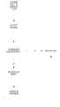
图1为本实用新型所述的基于单点感知的家庭用水智能监测设备的监测功能的流程框图;Fig. 1 is the flow chart diagram of the monitoring function of the household water intelligent monitoring equipment based on single-point perception described in the utility model;
图2为本实用新型所述的基于单点感知的家庭用水智能监测设备的监测功能中的用水事件提取的流程框图;Fig. 2 is the flow diagram of the water use event extraction in the monitoring function of the household water intelligent monitoring device based on single point perception described in the utility model;
图3为本实用新型所述的基于单点感知的家庭用水智能监测设备中所采用的转接板结构组成的示意图;Fig. 3 is a schematic diagram of the structural composition of the adapter plate adopted in the household water intelligent monitoring device based on single-point sensing described in the present invention;
图4为本实用新型所述的基于单点感知的家庭用水智能监测设备中所采用的国家仪器数据采集卡(National Instruments Data Acquisition:NI myDAQ)分解式轴测投影图;Fig. 4 is the decomposed axonometric projection diagram of the National Instruments Data Acquisition (NI myDAQ) adopted in the household water intelligent monitoring device based on single-point perception described in the utility model;
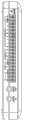
图5为本实用新型所述的基于单点感知的家庭用水智能监测设备中所采用的国家仪器数据采集卡(National Instruments Data Acquisition:NI myDAQ)20个接线端子连接器;Fig. 5 is the 20 terminal connectors of the National Instruments Data Acquisition (National Instruments Data Acquisition: NI myDAQ) adopted in the household water intelligent monitoring device based on single-point perception described in the utility model;
图6为本实用新型所述的基于单点感知的家庭用水智能监测设备的结构原理框图;Fig. 6 is a structural principle block diagram of the household water intelligent monitoring device based on single-point sensing described in the utility model;
图中:1.国家仪器数据采集卡,2.USB线缆,3.20个接线端子,4.音频线缆,5.DDM香蕉线缆。In the figure: 1. National Instruments data acquisition card, 2. USB cable, 3. 20 terminal blocks, 4. Audio cable, 5. DDM banana cable.
具体实施方式Detailed ways
下面结合附图对本实用新型作详细的描述:Below in conjunction with accompanying drawing, the utility model is described in detail:
本实用新型所述的基于单点感知的家庭用水智能监测设备针对现有技术所存在的缺陷,提出了更加全面地反映用户用水信息和更加合理的节能方法。利用用水事件发生时产生水压波动并且会向用水网络传播的特性与相应算法进行用水事件的判断,完成用水监测的目的。The household water intelligent monitoring device based on single-point sensing described in the utility model aims at the defects existing in the prior art, and proposes a more comprehensive reflection of user water consumption information and a more reasonable energy-saving method. Using the characteristics of water pressure fluctuations and propagating to the water network when water use events occur, and the corresponding algorithm to judge water use events, complete the purpose of water use monitoring.
参阅图1,本实用新型所述的基于单点感知的家庭用水智能监设备的监测功能的步骤如下:Referring to Fig. 1, the steps of the monitoring function of the household water intelligent monitoring equipment based on single-point perception described in the utility model are as follows:
1.基于单点感知的家庭用水智能监测设备初始化参数:1. Initialization parameters of household water intelligent monitoring equipment based on single-point perception:
所述的基于单点感知的家庭用水智能监测设初始化参数就是操作者(点击电脑操作界面上的开始按钮)将基于单点感知的家庭用水智能监测设备中的数据存储器进行清空,用水时间和用水量归零。The initialization parameter of the household water intelligent monitoring device based on single-point sensing is that the operator (click the start button on the computer operation interface) clears the data storage in the household water intelligent monitoring device based on single-point sensing, water consumption time and water consumption The amount is reset to zero.
2.基于单点感知的家庭用水智能监测设备等待用户通过电脑界面读取用水记录,用户可以随时读取用水数据记录。2. Based on single-point sensing, the intelligent household water monitoring equipment waits for the user to read the water consumption record through the computer interface, and the user can read the water consumption data record at any time.
3.基于单点感知的家庭用水智能监测设备等待是否有用水事件发生,如果没有用水事件发生,继续等待是否有用水事件发生,如果有用水事件发生,则进行下一步骤4。3. The intelligent household water monitoring device based on single-point perception waits for a water event to occur, if not, continues to wait for a water event to occur, and if there is a water event, proceed to the
4.基于单点感知的家庭用水智能监测设备判断是否发生了用水事件。用水事件根据水压变化快慢的情况分为两种情况:第一种情况是非缓慢用水事件发生,第二种情况是缓慢用水事件发生。这里的非缓慢用水事件如打开水龙头,打开淋浴喷头等会引起水压突变的用水事件,缓慢用水事件如冲厕所,这种用水过程相对缓慢,不会引起水压突变的用水事件。4. Based on the single-point perception of household water intelligent monitoring equipment to determine whether a water incident has occurred. Water consumption events are divided into two cases according to the speed of water pressure change: the first case is the occurrence of non-slow water use events, and the second case is the occurrence of slow water use events. The non-slow water use events here, such as turning on the faucet, turning on the shower head, etc., will cause sudden changes in water pressure. Slow water events, such as flushing the toilet, are relatively slow water use events that will not cause sudden changes in water pressure.
第一种,非缓慢用水事件(水龙头,淋浴喷头等能够引起水压突变的用水事件)判断,当水压值超出一定阈值范围时,利用用水事件开始点的水压值和用水事件结束点的水压值之差作为判断的依据,数学描述如下:The first type is non-slow water use event (faucet, shower head and other water use events that can cause sudden changes in water pressure). The difference between the water pressure values is used as the basis for judgment, and the mathematical description is as follows:

其中,Valueend是用水事件结束时间测得的电压值,Valuebeginning是用水事件开始时间测得的电压值。Wherein, Valueend is the voltage value measured at the end time of the water event, and Valuebeginning is the voltage value measured at the start time of the water event.
第二种,缓慢用水事件(冲厕所等用水过程相对缓慢,不会引起水压突变的用水事件。)的判断,当水压阈值没有超出一定范围,此时的判断用水事件的开关状态的方法是计算用水事件在开始处和第一个极值点处水压传感器采集到的电压值之差,这是由水压变化特性决定的。算法描述如下:The second type is the judgment of slow water use events (the water use process such as flushing the toilet is relatively slow and will not cause sudden changes in water pressure.) Judgment, when the water pressure threshold does not exceed a certain range, the method of judging the switch status of the water use event at this time It is to calculate the difference between the voltage value collected by the water pressure sensor at the beginning of the water use event and the first extreme point, which is determined by the characteristics of the water pressure change. The algorithm is described as follows:

其中,Valuefirst_extreme是用水事件第一个极值点的电压值,Valuebeginning是用水事件开始时的电压值。通过以上算法,得出是“打开阀门用水事件”(例如打开水龙头)还是“关闭阀门用水事件”(例如关闭水龙头)Among them, Valuefirst_extreme is the voltage value at the first extreme point of the water usage event, and Valuebeginning is the voltage value at the beginning of the water usage event. Through the above algorithm, it is determined whether it is an "opening valve water event" (such as opening a faucet) or a "closing valve water event" (such as closing a faucet)
5.参阅图2,基于单点感知的家庭用水智能监测设备判断出是何种用水事件;步骤如下:5. Referring to Figure 2, the intelligent household water monitoring equipment based on single-point perception can determine what kind of water use event it is; the steps are as follows:
1)基于单点感知的家庭用水智能监测设备开始对用水事件的水压数据进行采集,通过安装在水管中的水压传感器传过来的电压值,测得实时的水压值,并将所有水压的数据存在一个可读写的存储文件中。1) The household water intelligent monitoring equipment based on single-point sensing starts to collect the water pressure data of water use events, and measures the real-time water pressure value through the voltage value transmitted from the water pressure sensor installed in the water pipe, and sends all water pressure The compressed data is stored in a readable and writable storage file.
2)基于单点感知的家庭用水智能监测设备读取存储文件中的水压数据。2) Based on single-point sensing, intelligent household water monitoring equipment reads water pressure data stored in files.
3)基于单点感知的家庭用水智能监测设备对存储文件中的数据进行分析,用于侦测是什么用水事件,这里针对非缓慢用水事件和缓慢用水事件的分析方法分为两种算法。3) The intelligent household water monitoring equipment based on single-point perception analyzes the data in the stored files to detect what water consumption events are. Here, the analysis methods for non-slow water use events and slow water use events are divided into two algorithms.
算法1,由于原始水压力波形振荡数据包含很多高频噪声成分,因此首先通过一个低通滤波器,这个低通滤波器通过国家仪器数据采集卡配套的NI LabVIEW软件中的已经存在的低通滤波算法模块实现,将滤波后的数据作为原始处理数据,当水压数据信号超过一定的阈值时,表征发生了一个用水事件。这个阈值可以根据每个家庭用户静态水压的不同而调节。数学描述如下:
假设我们有一个已知的用水事件序列X{Xi∈Rn,i=1,2,…,n}和一个未知的用水事件序列Y={y1,y2…,yn},为了获得已知用水事件序列中和未知用水事件序列最匹配的用水事件序列,我们将已知用水事件序列都和未知用水事件序列进行内积计算:Suppose we have a known water use event sequence X{Xi ∈ Rn ,i=1, 2,…,n} and an unknown water use event sequence Y={y1 ,y2 …,yn }, for To obtain the water use event sequence that best matches the unknown water use event sequence in the known water use event sequence, we calculate the inner product of the known water use event sequence and the unknown water use event sequence:
通过计算,我们得到了一个由内积值组成的数组,下一步我们求出数组中的最大值。Through calculation, we get an array composed of inner product values, the next step we find the maximum value in the array.
max_value=max(valuei(x,y));i=1,2,3,...,n (4)max_value=max(valuei (x,y));i=1,2,3,...,n (4)
在应用中,我们可以设定一个相似程度的阈值。只有超过阈值的最大内积值才可以被认定为具有很高的相似性,即:In the application, we can set a threshold of similarity. Only the maximum inner product value exceeding the threshold can be considered as having a high similarity, namely:
max(|max(Valuei)-Pressurestatic|,|min(Valuei)-Pressurestatic|) (5)max(|max(Valuei )-Pressurestatic |,|min(Valuei )-Pressurestatic |) (5)
≥Threshold1,i=1,2,3...n≥Threshold1 , i=1,2,3...n
式子中Pressurestatic代表静态水压,即没有用水事件发生时的水压,这个水压值在有压力调节阀的家庭中是非常稳定的,Threshold1是根据实验分析得来的一个经验值,上述方法说明水压快速变化的情况,类似于求导。与已知用水事件序列的用水事件进行匹配看哪个最为接近,进而判断出是什么用水事件。如果成功判断出是何种用水事件,则进入步骤4)。Pressurestatic in the formula represents the static water pressure, that is, the water pressure when no water event occurs. This water pressure value is very stable in a family with a pressure regulating valve. Threshold1 is an empirical value obtained from experimental analysis. The above method accounts for the case of rapid changes in water pressure, similar to taking a derivative. Match the water use event with the known water use event sequence to see which one is the closest, and then determine what the water use event is. If it is successfully judged what kind of water use event it is, go to step 4).
算法2,采用算法1如果没成功判断出是何种用水事件,则使用算法2,当公式(6)中的数据极值之差超过一定范围时,可以认定一个缓慢变化的用水事件的发生,数学描述的式子如下:
|max(Valuei)-min(Valuei)|≥Threshold2,i=1,2,3...n (6)|max(Valuei )-min(Valuei )|≥Threshold2 , i=1,2,3...n (6)
式子中max(Valuei)是由公式(4)计算出的数组中的最大值,min(Valuei)是由公式(4)计算出的数组中的最小值,Threshold2是根据实验分析得来的一个经验值,上述公式的结果说明了水压快速变化的情况,类似于求导。当最大值和最小值的差超过Threshold2时,说明该未知用水事件序列与现在正在被计算的已知用水事件序列最为接近,进而判断出是什么用水事件。如果成功判断出是什么用水事件,则进入步骤4)。如果没有成功判断出用水事件则基于单点感知的家庭用水智能监测设备退出用水事件判断过程。In the formula, max(Valuei ) is the maximum value in the array calculated by formula (4), min(Valuei ) is the minimum value in the array calculated by formula (4), Threshold2 is obtained according to experimental analysis From an empirical value, the result of the above formula shows the rapid change of water pressure, which is similar to derivation. When the difference between the maximum value and the minimum value exceeds Threshold2 , it means that the unknown water use event sequence is the closest to the known water use event sequence being calculated, and then it is determined what the water use event is. If it is successfully judged what water use event is, go to step 4). If the water consumption event is not judged successfully, the household water use intelligent monitoring device based on single-point sensing exits the water consumption event judging process.
4)基于单点感知的家庭用水智能监测设备提取用水事件的结束时间和用水数据,将它们存储在存储器中。4) Based on single-point sensing, the household water use intelligent monitoring equipment extracts the end time of water use events and water use data, and stores them in the memory.
5)基于单点感知的家庭用水智能监测设备生成用水事件的原始处理数据,这些数据包括都发生了哪些用水事件(例如打开水龙头,冲马桶等事件)和基于单点感知的家庭用水智能监测设备中的水压传感器将水压转化为电压的原始数据。5) Household water intelligent monitoring equipment based on single-point perception generates raw processing data of water-use events, which include what water-use events have occurred (such as opening the tap, flushing the toilet, etc.) and household water intelligent monitoring equipment based on single-point perception The water pressure sensor in converts water pressure into voltage raw data.
6)基于单点感知的家庭用水智能监测设备退出该用水事件判断过程。6) The intelligent household water monitoring equipment based on single-point perception exits the judgment process of water consumption events.
6.基于单点感知的家庭用水智能监测设备判断是否是已知用水事件。知道了原始数据并知道了是什么用水事件,接下来要对该用水事件进行分析。如果是无法识别的用水事件,则基于单点感知的家庭用水智能监测设备会通知用户未知用水装置在使用水,通知方法是在电脑的界面上进行显示这个未知的用水事件的用水量,同时将用水量写入上位机的文件中,接下来如果不让设备停止工作,则基于单点感知的家庭用水智能监测设备开始新一轮的用水监测。这里通常是防止窃水事件和漏水事件的发生。如果是已知用水事件,进入步骤8。6. Based on single-point sensing, intelligent household water monitoring equipment judges whether it is a known water use event. Knowing the raw data and knowing what the water use event is, the next step is to analyze the water use event. If it is an unidentifiable water consumption event, the household water use intelligent monitoring device based on single-point sensing will notify the user that the unknown water use device is using water. The notification method is to display the water consumption of the unknown water use event on the computer interface, and at the same time The water consumption is written into the file of the host computer, and then if the device is not stopped, the smart household water monitoring device based on single-point sensing will start a new round of water monitoring. This is usually to prevent the occurrence of water theft and water leakage. If it is a known water use event, go to step 8.
7.基于单点感知的家庭用水智能监测设备判断用水事件结束,并对本次用水事件的用水量进行估计。如果判断出阀门关闭事件,就对用户使用多少水进行监测,对用水量进行合理的评估,告知用户此次用水量为多少,我们可以利用泊肃叶定律Q=△P/Rf来完成用水量的计算。7. Based on the single-point perception, the intelligent household water monitoring equipment judges the end of the water use event, and estimates the water consumption of this water use event. If the valve closing event is judged, monitor the amount of water used by the user, make a reasonable assessment of the water consumption, and inform the user of the water consumption this time. We can use Poiseuille’s law Q=△P/Rf to complete the water consumption Quantity calculation.
其中:△P.代表用水事件前后的压差,单位.Pa;Rf.液态阻抗,Rf=8uL/πr4,其中:r.代表水管的半径,单位.mm,μ.表示液体的粘性,单位.Pa.s,L.表示管子的长度,单位.cm。Among them: △P. Represents the pressure difference before and after the water event, unit. Pa; Rf . Liquid impedance, Rf = 8uL/πr4 , where: r. Represents the radius of the water pipe, unit. mm, μ. Represents the viscosity of the liquid , unit.Pa.s, L. indicates the length of the pipe, unit.cm.
每个用水装置的Rf都是不相同的,即使是同一个用水装置的冷热水阀的Rf都是不相同的,原因是冷热水在水管网络中经历了不同的路径。分别对每个用水装置的水管半径r、液体粘性u、管子长度L进行提前测量,然后计算出用水装置的液态阻抗Rf,然后通过泊肃叶定律评估出用水量,进入下一步骤8;如果判断阀门不是关闭,则直接进入步骤8,等待基于单点感知的家庭用水智能监测设备开始一个新的监测循环。The Rf of each water device is different, even the Rf of the hot and cold water valves of the same water device is different, because the hot and cold water have experienced different paths in the water pipe network. Measure the water pipe radius r, liquid viscosity u, and pipe length L of each water device respectively in advance, and then calculate the liquid resistance Rf of the water device, and then estimate the water consumption through Poiseuille's law, and enter the next step 8; If it is judged that the valve is not closed, then go directly to step 8, and wait for the single-point sensing-based household water intelligent monitoring device to start a new monitoring cycle.
8.将基于单点感知的家庭用水智能监测设备存储器中的数据处理成电脑可读取的文件输入输出形式,以便于用户对数据进行读取。8. Process the data in the memory of the household water intelligent monitoring device based on single-point perception into a computer-readable file input and output form, so that users can read the data.
9.等待整个基于单点感知的家庭用水监测设备的退出命令,如果没有退出命令,则回到步骤3,以此往复,基于单点感知的家庭用水智能监测设备监测用水量的变化。如果有退出命令,则基于单点感知的家庭用水智能监测设备停止监测,退出命令由电脑操作界面的退出按钮来执行,关闭用水的监测电脑用户界面。9. Wait for the exit command of the entire single-point sensing-based household water monitoring device. If there is no exit command, go back to
参阅图6,本实用新型所述的基于单点感知的家庭用水智能监测设备包括水压传感器、转接板、型号为NI myDAQ的国家仪器数据采集卡1、电脑与USB线缆2。其中美国国家虚拟仪器公司的型号为NI myDAQ的国家仪器数据采集卡1是本实用新型所述的基于单点感知的家庭用水智能监测设备的核心。Referring to Fig. 6, the household water intelligent monitoring device based on single-point sensing described in the utility model includes a water pressure sensor, an adapter board, a National Instruments
(1)水压传感器是由美国FORUN Technology公司生产的压力变送器,由接线端子、导线、水压传感部分、水龙头接头组成。其中:(1) The water pressure sensor is a pressure transmitter produced by FORUN Technology Company in the United States. It is composed of terminal blocks, wires, water pressure sensing parts, and faucet connectors. in:
接线端子由3根杜邦线插槽组成,间距2.54毫米(mm)。导线三根分别为参考电压输入线、地线、水压值转换为电压的信号线。The terminal block consists of 3 Dupont wire slots with a pitch of 2.54 millimeters (mm). The three wires are respectively the reference voltage input wire, the ground wire, and the signal wire for converting the water pressure value into a voltage.
水龙头接头为1/4阳螺纹接头属于标准件。材料为高强度塑料。适合测量的介质包括无腐蚀性的气体,水,油等。适用于壁挂炉,燃气炉,储气罐等各种水压、气压的压力测量。The faucet connector is a 1/4 male threaded connector which is a standard part. The material is high-strength plastic. Suitable media for measurement include non-corrosive gases, water, oil, etc. It is suitable for pressure measurement of various water pressure and air pressure such as wall-hung boilers, gas furnaces, and gas storage tanks.
水压传感器的技术指标为:量程范围:0—0.5兆帕斯卡(MPa);静态精度:±1.0%满量程(FS—Full Scale);输出信号范围:0.5—4.5伏(V);供电电压:5.0±0.5伏(V)直流电(DC)。The technical indicators of the water pressure sensor are: range: 0-0.5 megapascal (MPa); static accuracy: ±1.0% full scale (FS-Full Scale); output signal range: 0.5-4.5 volts (V); power supply voltage: 5.0±0.5 volts (V) direct current (DC).
(2)参阅图3,转接板由一个型号为PH2.54(毫米)间距的(三针)单排的插头2、一个型号为2.54(毫米)间距的(两针)单排的插头1、导线和型号为LT-BNC-50KY的BNC连接器组成。BNC连接器是一种用于同轴电缆的连接器,全称是Bayonet Nut Connector,即常说的细同轴电缆接口。(2) Referring to Figure 3, the adapter board consists of a (three-pin) single-
插头2中的3号脚与插头1中的2号脚同和+5V电压电线连接,插头2的1号脚与插头1中的1号脚同和地端电线连接,插头1中的1号脚与BNC连接器的接地端电线连接,插头2的2号脚与BNC连接器的插槽电线连接。插头1另一端的2号脚接型号为NI myDAQ的国家仪器数据采集卡1上的+5V,插头1另一端的1号脚接型号为NI myDAQ的国家仪器数据采集卡1上的地端;插头2的3号脚、2号脚、1号脚依次与水压传感器的三根线相连,1号脚连接水压传感器的地线,2号脚连接水压传感器的水压值转换为电压的输出信号线,3号脚连接水压传感器的电源线。
(3)型号为NI myDAQ的国家仪器数据采集卡1是一种使用NI LabVIEW软件开发的低成本便携式数据采集设备,可以使用它测量和分析实时信号。适用于电子设备和传感器测量,它采用USB接口,提供了模拟输入(AI)、模拟输出(AO)、数字输入和输出(DIO),音频、电源和数字万用表函数等。(3) The National Instruments
参阅图4,型号为NI myDAQ的国家仪器数据采集卡1主要能完成模拟输入输出、通过USB线缆2进行数字输入输出,下面针对每种不同的功能分别介绍:Referring to Figure 4, the National Instruments
1.模拟输入(AI):型号为NI myDAQ的国家仪器数据采集卡1带有2个模拟输入通道。上述通道可被配置为通用高阻抗差分电压输入或音频输入。模拟输入为多路复用,即通过一个模数转换器(ADC)对两个通道进行采样。在通用模式下,测量信号范围为±10V。每个通道可被测量的模拟输入高达200每秒千次采样(KS/s)。1. Analog input (AI): National Instruments
2.模拟输出(AO):型号为NI myDAQ的国家仪器数据采集卡1带有2个模拟输出通道。上述通道可被配置为通用电压输出或音频输出。两个通道均可用作数模转换器(DAC),因此可进行同步更新。在通用模式下,生成信号范围为±10V。2. Analog output (AO): The National Instruments
3.数字输入/输出(DIO):型号为NI myDAQ的国家仪器数据采集卡1带有8个DIO数据线。每条数据线为一个可编程函数接口(PFI),表示其可被配置为通用软件定时数字输入或输出,或可用作数字计数器的特殊函数输入或输出。电源:型号为NI myDAQ的国家仪器数据采集卡1有3个可供使用的电源,+15V电源、–15V电源和+5V电源。3. Digital Input/Output (DIO): National Instruments
4.型号为NI myDAQ的国家仪器数据采集卡1共有20个接线端子3,如图5就是接线端子的连接图。接线端子的各位的定义如表5.3所示。4. The National Instruments
表5.3接线端子信号说明Table 5.3 Terminal signal description

以上四部分的连接关系为:水压传感器中的水龙头接头即1/4阳螺纹接头接到家庭用水的水管上采集水压。水压传感器上有三根线,分别为红、白、蓝(不同传感器可能颜色不同但功能相同),分别为水压传感器的参考电源线、水压传感器的水压值转换为电压的输出信号线、水压传感器的地线。转接板上的插头1的2号脚接型号为NI myDAQ的国家仪器数据采集卡1上的+5V,插头1的1号脚接型号为NI myDAQ的国家仪器数据采集卡1上的地端(DGND);插头2的3号脚、2号脚、1号脚依次与水压传感器的三根线相连,即3号脚连接红色线即水压传感器的参考电源线,2号脚连接白色线即水压传感器的水压值转换为电压的输出信号线,1号脚连接蓝色线即水压传感器的地线。然后用线将型号为NI myDAQ的国家仪器数据采集卡1上的AI0接线端子引出连接BNC插头,BNC插头与转接板的BNC插槽连接,最后型号为NI myDAQ的国家仪器数据采集卡1采用配套的USB线缆2与电脑的USB接口连接。The connection relationship of the above four parts is: the faucet joint in the water pressure sensor, that is, the 1/4 male threaded joint, is connected to the water pipe for domestic water to collect water pressure. There are three wires on the water pressure sensor, which are red, white, and blue (different sensors may have different colors but have the same function), which are the reference power line of the water pressure sensor and the output signal line for converting the water pressure value of the water pressure sensor to voltage. , The ground wire of the water pressure sensor. The No. 2 pin of the
基于单点感知的家庭用水智能监测设备的工作原理:The working principle of household water intelligent monitoring equipment based on single point perception:
我们的家庭用水是形成了一个网络的,是指我们家庭用水形成了一个大的网络系统,相互联系,这个条件,是后续的用水检测的条件。为了防止输水管线中的压力突变对家庭用水装置造成损害,并使家庭管线中的水压保持在一个安全范围内,需要在家庭入水口处加一个压力调节阀。工作原理如下:只要供水线一侧的压力保持在设定值之上,家庭用水侧一端就会保持稳定的安全水压。家庭用水网络是一个闭环系统。当没有设备用水时,网络中的水压保持一个稳定值,这要归功于压力调节阀。在家庭用水形成网络的基础上,在水管中安置水压传感器,用于检测一个用水阀门被打开时水压在管线中形成的波动,我们可以把这种现象称为“浪涌”。通过在用水网络中安装一个水压传感器,可以感知每次用水设备工作时产生的“浪涌”现象,这样就为基于单点感知的家庭用水智能监测设备的监测提供了依据。几乎所有的用水事件都会产生“浪涌”现象。水压传感器检测水压的变化,并将水压的变化转化为电压的变化,再将水压传感器传来的模拟信号送入型号为NI myDAQ的国家仪器数据采集卡1的模拟量转化为数字量(A/D)通道内进行A/D转换,输出数字信号送给电脑处理。如果发生用水事件,则进行用水事件判断,否则继续监测等待。将上述模拟量送入型号为NI myDAQ的国家仪器数据采集卡1中后,主要看是否发生水闸的开关状态,如果发生则进行开关事件识别,否则继续读取数据,等待判断是否有水闸开关。判断出用水事件的开关状态后,对用水事件进行识别判断。主要通过以下三步完成用水事件判断功能:(1)初始化,(2)用水事件提取,(3)用水事件判断。为了最终的用水事件分类,需要提前准备每个设备的样本水压数据。包括开阀门事件和关阀门事件分别的样本数据。并且以一定的格式即通过LabVIEW中的簇数据格式存储到文件中。每个簇中包含两个基本的数据元素:字符串类型和双精度浮点型数组类型。字符串类型表征每个设备的名字,双精度浮点型数组表征每个设备的事件数据。每个设备都有两个数据单元。并且这两个数据单元分在两个文件中存储。通过文件名字的不同区分是打开阀门事件样本数据文件还是关闭阀门样本数据。是在上述功能完成后,进行用水量的计算。水量评估模块我们利用泊肃叶定律Q=△P/Rf完成计算,其中的△P代表用水事件前后的压差,可以通过实际的测量获得,最难测量的参数是Rf,每个用水装置的Rf都是不相同的,即使是同一个设备的冷热水阀的Rf都是不相同的,原因是冷热水在水管网络中经历了不同的路径。分别对每个设备的Rf提前评估,然后用一种一般化的方法完成未标准化的设备的Rf测量。最终我们对已用标准容器测量的设备的Rf评估得到了准确的计算结果。将以上完成的数据通过电脑的用户界面显示给用户,包括每个用水事件的用水量信息,是否有固定的用水模式,每个设备占总用水量的百分比等,并向用户提出更合理的用水建议。Our domestic water use has formed a network, which means that our domestic water use has formed a large network system and is interconnected. This condition is the condition for subsequent water use testing. In order to prevent the sudden change of pressure in the water pipeline from causing damage to the household water device, and to keep the water pressure in the household pipeline within a safe range, it is necessary to add a pressure regulating valve at the household water inlet. The working principle is as follows: As long as the pressure on one side of the water supply line remains above the set value, the domestic water side will maintain a stable and safe water pressure. The domestic water network is a closed loop system. When no equipment is using water, the water pressure in the network maintains a constant value thanks to the pressure regulating valve. On the basis of the domestic water network, a water pressure sensor is placed in the water pipe to detect the fluctuation of water pressure in the pipeline when a water valve is opened. We can call this phenomenon "surge". By installing a water pressure sensor in the water network, the "surge" phenomenon generated each time the water equipment works can be sensed, which provides a basis for the monitoring of household water intelligent monitoring equipment based on single-point sensing. Almost all water use events generate a "surge". The water pressure sensor detects the change of water pressure and converts the change of water pressure into a change of voltage, and then sends the analog signal from the water pressure sensor to the National Instruments
Claims (2)
Translated fromChinesePriority Applications (1)
| Application Number | Priority Date | Filing Date | Title |
|---|---|---|---|
| CN 201220526520CN202865924U (en) | 2012-10-15 | 2012-10-15 | Intelligent monitoring equipment for household water based on single-point perception |
Applications Claiming Priority (1)
| Application Number | Priority Date | Filing Date | Title |
|---|---|---|---|
| CN 201220526520CN202865924U (en) | 2012-10-15 | 2012-10-15 | Intelligent monitoring equipment for household water based on single-point perception |
Publications (1)
| Publication Number | Publication Date |
|---|---|
| CN202865924Utrue CN202865924U (en) | 2013-04-10 |
Family
ID=48032653
Family Applications (1)
| Application Number | Title | Priority Date | Filing Date |
|---|---|---|---|
| CN 201220526520Expired - Fee RelatedCN202865924U (en) | 2012-10-15 | 2012-10-15 | Intelligent monitoring equipment for household water based on single-point perception |
Country Status (1)
| Country | Link |
|---|---|
| CN (1) | CN202865924U (en) |
Cited By (3)
| Publication number | Priority date | Publication date | Assignee | Title |
|---|---|---|---|---|
| US9892463B1 (en) | 2014-04-25 | 2018-02-13 | State Farm Mutual Automobile Insurance Company | System and methods for community-based cause of loss determination |
| US9898912B1 (en) | 2014-10-07 | 2018-02-20 | State Farm Mutual Automobile Insurance Company | Systems and methods for automatically generating an escape route |
| US11423758B2 (en) | 2018-04-09 | 2022-08-23 | State Farm Mutual Automobile Insurance Company | Sensing peripheral heuristic evidence, reinforcement, and engagement system |
- 2012
- 2012-10-15CNCN 201220526520patent/CN202865924U/ennot_activeExpired - Fee Related
Cited By (57)
| Publication number | Priority date | Publication date | Assignee | Title |
|---|---|---|---|---|
| US11042137B1 (en) | 2014-04-25 | 2021-06-22 | State Farm Mutual Automobile Insurance Company | Systems and methods for managing the operation of devices within a property |
| US12423760B2 (en) | 2014-04-25 | 2025-09-23 | State Farm Mutual Automobile Insurance Company | Systems and methods for automatically mitigating risk of water damage |
| US10055793B1 (en) | 2014-04-25 | 2018-08-21 | State Farm Mutual Automobile Insurance Company | Systems and methods for managing insurance for devices located within a property based on insurance-related events |
| US10102585B1 (en) | 2014-04-25 | 2018-10-16 | State Farm Mutual Automobile Insurance Company | Systems and methods for automatically mitigating risk of property damage |
| US10181160B1 (en) | 2014-04-25 | 2019-01-15 | State Farm Mutual Automobile Insurance Company | Systems and methods for assigning damage caused by an insurance-related event |
| US12354170B2 (en) | 2014-04-25 | 2025-07-08 | State Farm Mutual Automobile Insurance Company | Systems and methods for automatically mitigating risk of property damage |
| US12315015B2 (en) | 2014-04-25 | 2025-05-27 | State Farm Mutual Automobile Insurance Company | Systems and methods for managing insurance associated with devices populated within a property |
| US12282966B2 (en) | 2014-04-25 | 2025-04-22 | State Farm Mutual Automobile Insurance Company | Systems and methods for predictively generating an insurance claim |
| US10282787B1 (en) | 2014-04-25 | 2019-05-07 | State Farm Mutual Automobile Insurance Company | Systems and methods for determining cause of loss to a property |
| US12190392B2 (en) | 2014-04-25 | 2025-01-07 | State Farm Mutual Automobile Insurance Company | Systems and methods for assigning damage caused by an insurance-related event |
| US11966982B2 (en) | 2014-04-25 | 2024-04-23 | State Farm Mutual Automobile Insurance Company | Systems and methods for automatically mitigating risk of property damage |
| US11823281B2 (en) | 2014-04-25 | 2023-11-21 | State Farm Mutual Automobile Insurance Company | Systems and methods for assigning damage caused by an insurance-related event |
| US11756134B2 (en) | 2014-04-25 | 2023-09-12 | State Farm Mutual Automobile Insurance Company | Systems and methods for homeowner-directed risk of property damage mitigation |
| US10514669B1 (en) | 2014-04-25 | 2019-12-24 | State Farm Mutual Automobile Insurance Company | Systems and methods for managing the operation of devices within a property |
| US11657459B1 (en) | 2014-04-25 | 2023-05-23 | State Farm Mutual Automobile Insurance Company | Systems and methods for predictively generating an insurance claim |
| US11651441B2 (en) | 2014-04-25 | 2023-05-16 | State Farm Mutual Automobile Insurance Company | Systems and methods for homeowner-directed risk of property damage mitigation |
| US11379924B2 (en) | 2014-04-25 | 2022-07-05 | State Farm Mutual Automobile Insurance Company | Systems and methods for automatically mitigating risk of property damage |
| US11361387B1 (en) | 2014-04-25 | 2022-06-14 | State Farm Mutual Automobile Insurance Company | Systems and methods for managing insurance associated with devices populated within a property |
| US10679292B1 (en) | 2014-04-25 | 2020-06-09 | State Farm Mutual Automobile Insurance Company | Systems and methods for managing insurance associated with devices populated within a property |
| US10685402B1 (en) | 2014-04-25 | 2020-06-16 | State Farm Mutual Automobile Insurance Company | Systems and methods for homeowner-directed risk of property damage mitigation |
| US10733671B1 (en) | 2014-04-25 | 2020-08-04 | State Farm Mutual Automobile Insurance Company | Systems and methods for predictively generating an insurance claim |
| US11354748B1 (en) | 2014-04-25 | 2022-06-07 | State Farm Mutual Automobile Insurance Company | Systems and methods for automatically mitigating risk of water damage |
| US10846800B1 (en) | 2014-04-25 | 2020-11-24 | State Farm Mutual Automobile Insurance Company | Systems and methods for automatically mitigating risk of property damage |
| US10922756B1 (en) | 2014-04-25 | 2021-02-16 | State Farm Mutual Automobile Insurance Company | Systems and methods for managing insurance for devices located within a property based on insurance-related events |
| US11270385B1 (en) | 2014-04-25 | 2022-03-08 | State Farm Mutual Automobile Insurance Company | Systems and methods for homeowner-directed risk of property damage mitigation |
| US11074659B1 (en) | 2014-04-25 | 2021-07-27 | State Farm Mutual Automobile Insurance Company | Systems and methods for community-based cause of loss determination |
| US11042942B1 (en) | 2014-04-25 | 2021-06-22 | State Farm Mutual Automobile Insurance Company | Systems and methods for determining cause of loss to a property |
| US9892463B1 (en) | 2014-04-25 | 2018-02-13 | State Farm Mutual Automobile Insurance Company | System and methods for community-based cause of loss determination |
| US11043098B1 (en) | 2014-10-07 | 2021-06-22 | State Farm Mutual Automobile Insurance Company | Systems and methods for automatically generating an escape route |
| US10522009B1 (en) | 2014-10-07 | 2019-12-31 | State Farm Mutual Automobile Insurance Company | Systems and methods for automatically responding to a fire |
| US11004320B1 (en) | 2014-10-07 | 2021-05-11 | State Farm Mutual Automobile Insurance Company | Systems and methods for analyzing sensor data to detect property intrusion events |
| US10943447B1 (en) | 2014-10-07 | 2021-03-09 | State Farm Mutual Automobile Insurance Company | Systems and methods for automatically responding to a fire |
| US11334040B2 (en) | 2014-10-07 | 2022-05-17 | State Farm Mutual Automobile Insurance Company | Systems and methods for automatically responding to a fire |
| US10795329B1 (en) | 2014-10-07 | 2020-10-06 | State Farm Mutual Automobile Insurance Company | Systems and methods for managing smart devices based upon electrical usage data |
| US10573146B1 (en) | 2014-10-07 | 2020-02-25 | State Farm Mutual Automobile Insurance Company | Systems and methods for improved assisted or independent living environments |
| US10573149B1 (en) | 2014-10-07 | 2020-02-25 | State Farm Mutual Automobile Insurance Company | Systems and methods for automatically generating an escape route |
| US11049078B1 (en) | 2014-10-07 | 2021-06-29 | State Farm Mutual Automobile Insurance Company | Systems and methods for responding to a broken circuit |
| US11423754B1 (en) | 2014-10-07 | 2022-08-23 | State Farm Mutual Automobile Insurance Company | Systems and methods for improved assisted or independent living environments |
| US9898912B1 (en) | 2014-10-07 | 2018-02-20 | State Farm Mutual Automobile Insurance Company | Systems and methods for automatically generating an escape route |
| US10282961B1 (en) | 2014-10-07 | 2019-05-07 | State Farm Mutual Automobile Insurance Company | Systems and methods for automatically generating an escape route |
| US10515372B1 (en) | 2014-10-07 | 2019-12-24 | State Farm Mutual Automobile Insurance Company | Systems and methods for managing building code compliance for a property |
| US11656585B1 (en) | 2014-10-07 | 2023-05-23 | State Farm Mutual Automobile Insurance Company | Systems and methods for managing smart devices based upon electrical usage data |
| US10249158B1 (en) | 2014-10-07 | 2019-04-02 | State Farm Mutual Automobile Insurance Company | Systems and methods for automatically responding to a fire |
| US10388135B1 (en) | 2014-10-07 | 2019-08-20 | State Farm Mutual Automobile Insurance Company | Systems and methods for analyzing sensor data to detect property intrusion events |
| US11815864B2 (en) | 2014-10-07 | 2023-11-14 | State Farm Mutual Automobile Insurance Company | Systems and methods for managing building code compliance for a property |
| US10356303B1 (en) | 2014-10-07 | 2019-07-16 | State Farm Mutual Automobile Insurance Company | Systems and methods for controlling smart devices based upon image data from image sensors |
| US12321142B2 (en) | 2014-10-07 | 2025-06-03 | State Farm Mutual Automobile Insurance Company | Systems and methods for improved assisted or independent living environments |
| US10282788B1 (en) | 2014-10-07 | 2019-05-07 | State Farm Mutual Automobile Insurance Company | Systems and methods for managing service log information |
| US10353359B1 (en) | 2014-10-07 | 2019-07-16 | State Farm Mutual Automobile Insurance Company | Systems and methods for managing smart devices based upon electrical usage data |
| US10346811B1 (en) | 2014-10-07 | 2019-07-09 | State Farm Mutual Automobile Insurance Company | Systems and methods for responding to a broken circuit |
| US12314020B2 (en) | 2014-10-07 | 2025-05-27 | State Farm Mutual Automobile Insurance Company | Systems and methods for managing smart devices based upon electrical usage data |
| US11423758B2 (en) | 2018-04-09 | 2022-08-23 | State Farm Mutual Automobile Insurance Company | Sensing peripheral heuristic evidence, reinforcement, and engagement system |
| US12205450B2 (en) | 2018-04-09 | 2025-01-21 | State Farm Mutual Automobile Insurance Company | Sensing peripheral heuristic evidence, reinforcement, and engagement system |
| US11887461B2 (en) | 2018-04-09 | 2024-01-30 | State Farm Mutual Automobile Insurance Company | Sensing peripheral heuristic evidence, reinforcement, and engagement system |
| US11869328B2 (en) | 2018-04-09 | 2024-01-09 | State Farm Mutual Automobile Insurance Company | Sensing peripheral heuristic evidence, reinforcement, and engagement system |
| US11670153B2 (en) | 2018-04-09 | 2023-06-06 | State Farm Mutual Automobile Insurance Company | Sensing peripheral heuristic evidence, reinforcement, and engagement system |
| US11462094B2 (en) | 2018-04-09 | 2022-10-04 | State Farm Mutual Automobile Insurance Company | Sensing peripheral heuristic evidence, reinforcement, and engagement system |
Similar Documents
| Publication | Publication Date | Title |
|---|---|---|
| CN202865924U (en) | Intelligent monitoring equipment for household water based on single-point perception | |
| CN103176066A (en) | Digitization power quality monitoring device | |
| CN206683684U (en) | A kind of intellectual water closet Auto-Test System | |
| CN102830317B (en) | A kind of distributed power generation dispersity monitoring device | |
| CN115146977A (en) | Enterprise energy efficiency data management method and system based on Internet of things | |
| CN103234896B (en) | Hand-held quick corrosion tester for petroleum pipelines | |
| CN104344862A (en) | Detection method for FCM10A type fuel consumption meter | |
| CN102912829B (en) | Single-point-sensing-based household water intelligent monitoring method and equipment thereof | |
| CN104407271A (en) | Signal receiver for cable identification device | |
| CN202794327U (en) | Household electricity intelligent monitoring device based on single-point perception | |
| CN208223793U (en) | Intelligent monitor for ship valve | |
| CN102901869B (en) | Method and equipment for intelligently monitoring household electricity based on single-point sensing | |
| CN202370506U (en) | Liquid level tester of coalbed methane well | |
| CN102156207A (en) | Distributed intelligent electric energy recording system and detecting method thereof | |
| CN202381313U (en) | Pump efficiency detector | |
| CN201662550U (en) | Dirt thermoresistance tester | |
| CN201281730Y (en) | Electric network loop-closing electricity-switching detection device | |
| CN109322819B (en) | An online energy efficiency test and energy consumption analysis system and method for a pump system | |
| CN111982231A (en) | A low-power water level integrated intelligent monitoring system | |
| CN202512172U (en) | Intelligent machine electrical impedance sensor for monitoring structure health conditions | |
| CN112525270B (en) | Novel water meter data acquisition method and data acquisition system | |
| CN201348616Y (en) | Non-combustibility test control system | |
| CN201092853Y (en) | Well head built-in oil-water rate detecting instrument | |
| CN204718726U (en) | Hydrant device for detecting water pressure | |
| CN204269754U (en) | A signal receiver for a cable identification device |
Legal Events
| Date | Code | Title | Description |
|---|---|---|---|
| C14 | Grant of patent or utility model | ||
| GR01 | Patent grant | ||
| CF01 | Termination of patent right due to non-payment of annual fee | Granted publication date:20130410 Termination date:20151015 | |
| EXPY | Termination of patent right or utility model |