CN202821564U - bone fixation system - Google Patents
bone fixation systemDownload PDFInfo
- Publication number
- CN202821564U CN202821564UCN2010900010422UCN201090001042UCN202821564UCN 202821564 UCN202821564 UCN 202821564UCN 2010900010422 UCN2010900010422 UCN 2010900010422UCN 201090001042 UCN201090001042 UCN 201090001042UCN 202821564 UCN202821564 UCN 202821564U
- Authority
- CN
- China
- Prior art keywords
- bone fixation
- fixation system
- compression element
- main body
- rod
- Prior art date
- Legal status (The legal status is an assumption and is not a legal conclusion. Google has not performed a legal analysis and makes no representation as to the accuracy of the status listed.)
- Expired - Fee Related
Links
Images


Classifications
- A—HUMAN NECESSITIES
- A61—MEDICAL OR VETERINARY SCIENCE; HYGIENE
- A61B—DIAGNOSIS; SURGERY; IDENTIFICATION
- A61B17/00—Surgical instruments, devices or methods
- A61B17/56—Surgical instruments or methods for treatment of bones or joints; Devices specially adapted therefor
- A61B17/58—Surgical instruments or methods for treatment of bones or joints; Devices specially adapted therefor for osteosynthesis, e.g. bone plates, screws or setting implements
- A61B17/68—Internal fixation devices, including fasteners and spinal fixators, even if a part thereof projects from the skin
- A61B17/70—Spinal positioners or stabilisers, e.g. stabilisers comprising fluid filler in an implant
- A61B17/7001—Screws or hooks combined with longitudinal elements which do not contact vertebrae
- A61B17/7002—Longitudinal elements, e.g. rods
- A61B17/7019—Longitudinal elements having flexible parts, or parts connected together, such that after implantation the elements can move relative to each other
- A61B17/7026—Longitudinal elements having flexible parts, or parts connected together, such that after implantation the elements can move relative to each other with a part that is flexible due to its form
- A—HUMAN NECESSITIES
- A61—MEDICAL OR VETERINARY SCIENCE; HYGIENE
- A61B—DIAGNOSIS; SURGERY; IDENTIFICATION
- A61B17/00—Surgical instruments, devices or methods
- A61B17/56—Surgical instruments or methods for treatment of bones or joints; Devices specially adapted therefor
- A61B17/58—Surgical instruments or methods for treatment of bones or joints; Devices specially adapted therefor for osteosynthesis, e.g. bone plates, screws or setting implements
- A61B17/68—Internal fixation devices, including fasteners and spinal fixators, even if a part thereof projects from the skin
- A61B17/70—Spinal positioners or stabilisers, e.g. stabilisers comprising fluid filler in an implant
- A61B17/7001—Screws or hooks combined with longitudinal elements which do not contact vertebrae
- A61B17/7002—Longitudinal elements, e.g. rods
- A61B17/7019—Longitudinal elements having flexible parts, or parts connected together, such that after implantation the elements can move relative to each other
- A61B17/7022—Tethers, i.e. longitudinal elements capable of transmitting tension only, e.g. straps, sutures or cables
- A—HUMAN NECESSITIES
- A61—MEDICAL OR VETERINARY SCIENCE; HYGIENE
- A61B—DIAGNOSIS; SURGERY; IDENTIFICATION
- A61B17/00—Surgical instruments, devices or methods
- A61B17/56—Surgical instruments or methods for treatment of bones or joints; Devices specially adapted therefor
- A61B17/58—Surgical instruments or methods for treatment of bones or joints; Devices specially adapted therefor for osteosynthesis, e.g. bone plates, screws or setting implements
- A61B17/68—Internal fixation devices, including fasteners and spinal fixators, even if a part thereof projects from the skin
- A61B17/70—Spinal positioners or stabilisers, e.g. stabilisers comprising fluid filler in an implant
- A61B17/7001—Screws or hooks combined with longitudinal elements which do not contact vertebrae
- A61B17/7032—Screws or hooks with U-shaped head or back through which longitudinal rods pass
- A—HUMAN NECESSITIES
- A61—MEDICAL OR VETERINARY SCIENCE; HYGIENE
- A61B—DIAGNOSIS; SURGERY; IDENTIFICATION
- A61B17/00—Surgical instruments, devices or methods
- A61B17/56—Surgical instruments or methods for treatment of bones or joints; Devices specially adapted therefor
- A61B17/58—Surgical instruments or methods for treatment of bones or joints; Devices specially adapted therefor for osteosynthesis, e.g. bone plates, screws or setting implements
- A61B17/68—Internal fixation devices, including fasteners and spinal fixators, even if a part thereof projects from the skin
- A61B17/70—Spinal positioners or stabilisers, e.g. stabilisers comprising fluid filler in an implant
- A61B17/7053—Spinal positioners or stabilisers, e.g. stabilisers comprising fluid filler in an implant with parts attached to bones or to each other by flexible wires, straps, sutures or cables
- A—HUMAN NECESSITIES
- A61—MEDICAL OR VETERINARY SCIENCE; HYGIENE
- A61B—DIAGNOSIS; SURGERY; IDENTIFICATION
- A61B17/00—Surgical instruments, devices or methods
- A61B17/56—Surgical instruments or methods for treatment of bones or joints; Devices specially adapted therefor
- A61B17/58—Surgical instruments or methods for treatment of bones or joints; Devices specially adapted therefor for osteosynthesis, e.g. bone plates, screws or setting implements
- A61B17/68—Internal fixation devices, including fasteners and spinal fixators, even if a part thereof projects from the skin
- A61B17/70—Spinal positioners or stabilisers, e.g. stabilisers comprising fluid filler in an implant
- A61B17/7062—Devices acting on, attached to, or simulating the effect of, vertebral processes, vertebral facets or ribs ; Tools for such devices
- A—HUMAN NECESSITIES
- A61—MEDICAL OR VETERINARY SCIENCE; HYGIENE
- A61B—DIAGNOSIS; SURGERY; IDENTIFICATION
- A61B17/00—Surgical instruments, devices or methods
- A61B17/56—Surgical instruments or methods for treatment of bones or joints; Devices specially adapted therefor
- A61B17/58—Surgical instruments or methods for treatment of bones or joints; Devices specially adapted therefor for osteosynthesis, e.g. bone plates, screws or setting implements
- A61B17/68—Internal fixation devices, including fasteners and spinal fixators, even if a part thereof projects from the skin
- A61B17/80—Cortical plates, i.e. bone plates; Instruments for holding or positioning cortical plates, or for compressing bones attached to cortical plates
- A61B17/8028—Cushions, i.e. elements forming interface between bone plate and bone
- A—HUMAN NECESSITIES
- A61—MEDICAL OR VETERINARY SCIENCE; HYGIENE
- A61B—DIAGNOSIS; SURGERY; IDENTIFICATION
- A61B17/00—Surgical instruments, devices or methods
- A61B17/56—Surgical instruments or methods for treatment of bones or joints; Devices specially adapted therefor
- A61B17/58—Surgical instruments or methods for treatment of bones or joints; Devices specially adapted therefor for osteosynthesis, e.g. bone plates, screws or setting implements
- A61B17/68—Internal fixation devices, including fasteners and spinal fixators, even if a part thereof projects from the skin
- A61B17/82—Internal fixation devices, including fasteners and spinal fixators, even if a part thereof projects from the skin for bone cerclage
- A—HUMAN NECESSITIES
- A61—MEDICAL OR VETERINARY SCIENCE; HYGIENE
- A61B—DIAGNOSIS; SURGERY; IDENTIFICATION
- A61B17/00—Surgical instruments, devices or methods
- A61B17/56—Surgical instruments or methods for treatment of bones or joints; Devices specially adapted therefor
- A61B17/58—Surgical instruments or methods for treatment of bones or joints; Devices specially adapted therefor for osteosynthesis, e.g. bone plates, screws or setting implements
- A61B17/68—Internal fixation devices, including fasteners and spinal fixators, even if a part thereof projects from the skin
- A61B17/84—Fasteners therefor or fasteners being internal fixation devices
- A61B17/842—Flexible wires, bands or straps
Landscapes
- Health & Medical Sciences (AREA)
- Orthopedic Medicine & Surgery (AREA)
- Life Sciences & Earth Sciences (AREA)
- Surgery (AREA)
- Neurology (AREA)
- Heart & Thoracic Surgery (AREA)
- Engineering & Computer Science (AREA)
- Biomedical Technology (AREA)
- Nuclear Medicine, Radiotherapy & Molecular Imaging (AREA)
- Medical Informatics (AREA)
- Molecular Biology (AREA)
- Animal Behavior & Ethology (AREA)
- General Health & Medical Sciences (AREA)
- Public Health (AREA)
- Veterinary Medicine (AREA)
- Surgical Instruments (AREA)
Abstract
Description
Translated fromChinese技术领域technical field
本公开总体上涉及用于将骨头固定至杆的系统和方法。这种系统和方法可有助于将骨头和杆以期望的构造或以特别的相对位置保持在一起。尤其,所述骨头可以是脊椎的横突或椎板。The present disclosure generally relates to systems and methods for securing bones to rods. Such systems and methods can help hold the bone and rod together in a desired configuration or in a particular relative position. In particular, the bone may be the transverse process or lamina of the spine.
背景技术Background technique
本发明的一个应用领域是将骨头固定于期望位置,例如以帮助断裂的愈合或脊柱侧凸的治疗,或者矫正脊骨的异常弯曲。其他骨头缺陷和异常也可受益于本发明。One field of application of the invention is the fixation of bones in desired positions, for example to aid in the healing of fractures or the treatment of scoliosis, or to correct abnormal curvatures of the spine. Other bone defects and abnormalities may also benefit from the present invention.
脊骨由通常沿着脊椎轴线从腰椎至颈椎对准的叠置椎骨形成,每个椎骨都具有作为椎体的前部部件以及作为椎弓(神经弓)的后部部件,前部部件和后部部件包围椎孔。每个椎弓由一对椎弓根和一对椎板形成,并且横突和/或棘突(或神经棘)由此突出。横突和棘突与椎孔相对地突出。The spine is formed of superimposed vertebrae aligned generally along the spinal axis from the lumbar to the cervical spine, each vertebra having an anterior part that is the vertebral body and a posterior part that is the vertebral arch (nerve arch), an anterior part and a posterior The outer part surrounds the vertebral foramen. Each arch is formed by a pair of pedicles and a pair of lamina, from which the transverse processes and/or spinous processes (or neural spines) project. The transverse process and spinous process protrude opposite the foramen.
当椎骨相互铰接时,椎体形成用于头部和躯干支撑的坚固支柱,并且椎孔构成用于保护脊髓的通道。在每对椎骨之间,具有一侧上一个的两个孔隙,椎间孔,用于脊神经和血管的传输。As the vertebrae articulate with each other, the vertebral bodies form strong pillars for head and trunk support, and the vertebral foramina form passages for protecting the spinal cord. Between each pair of vertebrae, there are two cavities, one on one side, the intervertebral foramina, for the transmission of spinal nerves and blood vessels.
如果人的脊骨具有异常弯曲,椎骨通常相对彼此和相对于所述脊椎轴线倾斜。椎骨在一侧上的侧缘因此更靠近在一起并且限定凹形轮廓,而另一侧上的侧缘更远离并且限定凸形轮廓。If a person has an abnormal curvature of the spine, the vertebrae are usually tilted relative to each other and to the spinal axis. The lateral edges of the vertebrae on one side are thus closer together and define a concave profile, while the lateral edges on the other side are further apart and define a convex profile.
作为这种倾斜的补救措施,为了矫直脊柱,椎骨在凹侧上的侧缘能彼此远离地移动并且支撑为彼此间具有一个距离,这个距离基本上等于凸侧上的侧缘之间的距离。为了这么做,可使用不同种类的设备。As a remedy for this inclination, in order to straighten the spine, the side edges of the vertebrae on the concave side can be moved away from each other and supported with a distance between each other that is substantially equal to the distance between the side edges on the convex side . In order to do this, different kinds of equipment can be used.
现有技术已知的第一种设备是钩和杆系统,其具有钩在椎孔内壁上的钩以及用于将两个或更多的钩连接在一起的杆,从而将椎骨相对彼此保持于正确位置中。钩和杆系统的已知例子例如在PCT专利申请WO2005/023126和美国专利US 4269178中公开。The first device known in the prior art is the hook and rod system, which has a hook hooked on the inner wall of the vertebral foramen and a rod for connecting two or more hooks together, thereby holding the vertebrae in relation to each other. in the correct position. Known examples of hook and rod systems are eg disclosed in PCT patent application WO2005/023126 and US patent US 4269178.
然而,使用钩很困难,因为其使用增加了医生(或其他操作人员)可能会接触并潜在地损坏沿着椎孔延伸的脊髓的风险(这会导致患者的瘫痪)。However, using a hook is difficult because its use increases the risk that the physician (or other operator) may touch and potentially damage the spinal cord running along the foramen (which can lead to paralysis of the patient).
另一种已知设备是螺钉和杆系统,其具有螺旋入椎骨的螺钉以及用于将两个或更多螺钉连接在一起的杆,从而将椎骨相对彼此保持于正确位置。螺钉和杆系统的已知例子例如在欧洲专利EP 1575433B1中公开。Another known device is the screw and rod system, which has a screw threaded into a vertebra and a rod for connecting two or more screws together, thereby holding the vertebrae in the correct position relative to each other. A known example of a screw and rod system is for example disclosed in European patent EP 1575433B1.
螺钉通常具有郁金香形头部并成对地插入椎骨的后壁上的棘突的每侧上的弓根。螺钉因此构成椎骨上的用于保持椎骨的固定点。然而,螺钉插入椎骨的弓根,弓根在一些情况下很小或已经退化并且会受损或不会提供足够的力量以永久地保持螺钉。The screws usually have tulip-shaped heads and are inserted in pairs into the pedicles on each side of the spinous processes on the back wall of the vertebrae. The screw thus constitutes a fixation point on the vertebra for holding the vertebra. However, the screws are inserted into the pedicles of the vertebrae, which in some cases are small or degenerated and can be damaged or not provide enough strength to permanently hold the screws.
另一种已知设备是WO 2009/047352中公开的用于将骨头固定至杆的系统。其包括杆、阻塞体以及适合于包围骨头(即在其周围形成环路)的适形细长元件。在使用这种系统时,细长元件在所述骨头周围经过并穿过阻塞体,并且杆装载入阻塞体。拉动细长元件的端部以将张力应用于细长元件,并且细长元件和杆借助于同一紧固系统同时地紧固至阻塞体,部分细长元件被夹持于杆和阻塞体之间。这种系统没有带来彻底的满意度,因为医生(或其他操作人员)可能难以操纵。实际上,细长元件和杆需要在一单个步骤中紧固至阻塞体,并且因此在将杆紧固至阻塞体时细长元件需要保持于期望的张力之下。Another known device is the system for fixing bone to a rod disclosed in WO 2009/047352. It comprises a rod, a blocking body and a conformable elongate member adapted to enclose (ie form a loop around) bone. In using such a system, the elongated element is passed around the bone and through the blocking body, and the rod is loaded into the blocking body. The end of the elongated element is pulled to apply tension to the elongated element, and the elongated element and the rod are simultaneously fastened to the blocking body by means of the same fastening system, with part of the elongated element being clamped between the rod and the blocking body . Such systems do not lead to complete satisfaction because the physician (or other operator) may be difficult to maneuver. In fact, the elongated element and the rod need to be fastened to the blocking body in a single step, and thus the elongated element needs to be kept under the desired tension when fastening the rod to the blocking body.
发明内容Contents of the invention
根据本公开的一个实施例,提供了一种用于将骨头固定至杆的骨头固定系统,其包括:According to one embodiment of the present disclosure, there is provided a bone fixation system for fixing a bone to a rod comprising:
—适形的细长元件,其具有第一自由端部、第二自由端部以及其间的中间部分;- a conformable elongated element having a first free end, a second free end and an intermediate portion therebetween;
—主体;-main body;
—第一紧固设备或装置,用来将杆的一部分紧固至主体;以及- a first fastening device or device for fastening a part of the rod to the body; and
—第二紧固设备或装置,用于将细长元件的自由端部紧固至主体,第二紧固设备或装置与第一紧固设备或装置不同,并且第二紧固设备或装置适合与第一紧固设备或装置独立地操作。- a second fastening device or device for fastening the free end of the elongate element to the body, the second fastening device or device being different from the first fastening device or device, and the second fastening device or device being suitable for Operates independently of the first fastening device or device.
与现有技术的骨头固定系统相比,这种骨头固定系统操作更安全且更容易。更具体地,由于第二紧固装置与第一紧固装置不同并且由于第二紧固装置可独立于第一紧固装置操作,能在第一步骤中调节细长元件的张力并且将细长元件紧固至主体并且在第二步骤中将杆紧固至主体(或者反之)。This bone fixation system is safer and easier to operate than prior art bone fixation systems. More specifically, since the second fastening device is different from the first fastening device and since the second fastening device is operable independently of the first fastening device, the tension of the elongated element can be adjusted in the first step and the elongated The element is fastened to the body and in a second step the rod is fastened to the body (or vice versa).
而且,细长元件可由呈现一定量弹性的材料制成以使得,即使在医生已经拉动细长元件的自由端部并将其锁定就位之后,细长元件也允许骨头和杆之间的有限量的相对运动同时提供稳定效果,从而提供所谓的动态稳定化。Also, the elongated element may be made of a material that exhibits a certain amount of elasticity so that, even after the physician has pulled the free end of the elongated element and locked it in place, the elongated element allows a limited amount of movement between the bone and the rod. The relative movement of both provides a stabilizing effect, thereby providing so-called dynamic stabilization.
根据一个实施例,第二紧固装置包括可相对于主体移动的压缩元件,压缩元件和主体都限定细长元件的自由端可插入穿过其间的夹持表面,所述自由端通过相对于主体移动压缩元件而夹持于所述夹持表面之间。According to one embodiment, the second fastening means comprises a compression element movable relative to the body, both the compression element and the body defining a clamping surface through which the free end of the elongated element can be inserted, said free end being passed relative to the body. A compressive element is moved to be clamped between the clamping surfaces.
根据一个实施例,主体是空心的,从其下端至其上端沿着第一轴线延伸,并且包括:According to one embodiment, the body is hollow, extends along a first axis from its lower end to its upper end, and comprises:
—主要部分,其具有向上延伸的侧壁,侧壁在其间限定沿着所述第一轴线延伸并且在其上端处开口至主体外部的第一内部通道,以及- a main portion having upwardly extending side walls defining therebetween a first internal passage extending along said first axis and opening at its upper end to the exterior of the body, and
—底部,其定位于主要部分的下面并且设置有延伸穿过底部的整个厚度且与第一内部通道相通的第二内部通道。- A bottom positioned below the main part and provided with a second internal channel extending through the entire thickness of the bottom and communicating with the first internal channel.
在这个实施例中,压缩元件可定位于所述底部的下面并且可相对于所述底部移动,压缩元件和底部都限定所述夹持表面,并且该骨头固定系统可包括锁定机构,其穿过第二内部通道并且将操作来引起压缩元件相对于底部移动。In this embodiment, a compression element may be positioned below said base and is movable relative to said base, both the compression element and base define said gripping surface, and the bone fixation system may include a locking mechanism that passes through The second internal channel will also operate to cause movement of the compression element relative to the base.
由于这种构造,骨头固定系统具有紧凑设计并且易于操作。而且,锁定机构可通过第一内部通道接近和操作,并且因此可用穿过第一内部通道的工具操作,以将细长元件紧固至主体。因而,锁定机构易于由医生接近和操作。Due to this configuration, the bone fixation system has a compact design and is easy to handle. Furthermore, the locking mechanism is accessible and operable through the first internal passage, and thus operable with a tool passed through the first internal passage, to secure the elongate member to the body. Thus, the locking mechanism is easily accessible and operable by a physician.
根据一个实施例,压缩元件设置有螺纹孔并且所述锁定机构包括第一螺钉,第一螺钉具有头部和带有外螺纹的轴,螺钉轴穿过第二内部通道,螺钉头支承于底部的上表面上并且具有允许第一螺钉受驱的轮廓,并且螺钉轴的外螺纹与压缩元件的螺纹孔相啮合。According to one embodiment, the compression element is provided with a threaded hole and said locking mechanism comprises a first screw having a head and a shaft with an external thread, the screw shaft passes through the second internal channel, the screw head is supported on the bottom The upper surface is contoured to allow the first screw to be driven, and the external thread of the screw shaft engages the threaded hole of the compression element.
根据另一个实施例,底部的第二内部通道设置有内螺纹并且压缩元件具有形成所述锁定机构的突起部分。所述突起部分向上延伸,在其上端上具有允许突起部分受驱的轮廓,并且设置有与所述内螺纹相啮合的外螺纹。According to another embodiment, the second internal channel of the bottom is provided with an internal thread and the compression element has a protruding portion forming said locking mechanism. The protruding portion extends upwards, has a profile on its upper end that allows the protruding portion to be driven, and is provided with an external thread that engages with the internal thread.
根据本公开的一个实施例,还提供了一种用于将骨头固定至杆的方法,其包括步骤:According to one embodiment of the present disclosure, there is also provided a method for securing a bone to a rod comprising the steps of:
—让适形的细长元件经过所述骨头周围并穿过根据本公开的骨头固定系统;- passing a conformable elongated element around said bone and through a bone fixation system according to the present disclosure;
—通过拉动细长元件的端部而将张力应用于细长元件;- applying tension to the elongated element by pulling the end of the elongated element;
—借助于所述第二紧固装置将细长元件紧固至主体;- fastening the elongated element to the body by means of said second fastening means;
—将杆的一部分装载入主体;- loading part of the rod into the body;
—借助于所述第一紧固装置将杆的这个部分紧固至主体。- fastening this part of the rod to the body by means of said first fastening means.
根据以上方法,细长元件可在将杆部分紧固至主体之前紧固至主体,或者反之。According to the above method, the elongate element may be fastened to the body before the stem portion is fastened to the body, or vice versa.
对于医生,该方法易于使用,并且更具体地,有效地用于将两个或更多椎骨相对彼此保持于正确位置。为了这么做,医生(或其他操作人员)使用至少一个骨头固定系统并且让该系统的细长元件经过脊椎的横突或椎板周围。This method is easy to use for the physician and, more specifically, effective for maintaining two or more vertebrae in the correct position relative to each other. To do so, the physician (or other operator) uses at least one bone fixation system and passes the elongated member of the system around the transverse processes or lamina of the spine.
优选地,医生使用相应于椎骨数目的若干细长元件和骨头固定系统,用一个杆将骨头固定系统连接在一起。如果椎骨需要保持于棘突的每侧上,优选地使用相应于椎骨数目两倍的若干细长元件和骨头固定系统以及两个连接杆(棘突的每侧上放置一个杆)。Preferably, the physician uses several elongated elements corresponding to the number of vertebrae and the bone fixation system, connected together with a rod. If the vertebrae need to be held on each side of the spinous process, it is preferable to use several elongated elements corresponding to twice the number of vertebrae and the bone fixation system and two connecting rods (one placed on each side of the spinous process).
该方法还具有与使用根据本公开的骨头固定系统相关联的优点。This method also has advantages associated with using the bone fixation system according to the present disclosure.
根据一个实施例,该方法使用根据本公开的骨头固定系统,并且包括用穿过第一内部通道的工具操作该系统的锁定机构以将细长元件紧固至主体的步骤。According to one embodiment, the method uses a bone fixation system according to the present disclosure and includes the step of operating a locking mechanism of the system with a tool passed through the first internal passage to secure the elongate element to the body.
附图说明Description of drawings
在附图中,同样的参考符号一般来说在不同的视图中涉及相同的部分。而且,不同实施例的具有类似功能的部分由相同的参考标号加上100、200等来标识。In the drawings, like reference symbols generally refer to like parts in the different views. Also, parts of different embodiments having similar functions are identified by the same reference numerals plus 100, 200, etc. FIG.
附图无需按比例,替代地要强调的是示出本发明的原理。The drawings are not necessarily to scale, emphasis instead being placed upon illustrating the principles of the invention.
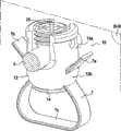
图1是根据本公开的骨头固定系统的示例的透视图;1 is a perspective view of an example of a bone fixation system according to the present disclosure;
图2是图1的骨头固定系统的局部透视图;Figure 2 is a partial perspective view of the bone fixation system of Figure 1;
图3是图1的骨头固定系统沿着平面III-III截取的截面图;Fig. 3 is a sectional view taken along plane III-III of the bone fixation system of Fig. 1;
图4是根据本公开的骨头固定系统的另一个示例的截面图;4 is a cross-sectional view of another example of a bone fixation system according to the present disclosure;
图5是根据本公开的骨头固定系统的另一个示例的透视图;5 is a perspective view of another example of a bone fixation system according to the present disclosure;
图6是图5的骨头固定系统沿着平面VI-VI截取的截面图;Fig. 6 is a sectional view taken along plane VI-VI of the bone fixation system of Fig. 5;
图7是根据本公开的骨头固定系统的另一个示例的截面图;7 is a cross-sectional view of another example of a bone fixation system according to the present disclosure;
图8是根据本公开的骨头固定系统的另一个示例的截面图;8 is a cross-sectional view of another example of a bone fixation system according to the present disclosure;
图9是根据本公开的骨头固定系统的另一个示例的截面图;9 is a cross-sectional view of another example of a bone fixation system according to the present disclosure;
图10是图9的骨头固定系统沿着平面X-X截取的截面图;Fig. 10 is a sectional view of the bone fixation system of Fig. 9 taken along the plane X-X;
图11是根据本公开的骨头固定系统的另一个示例的截面图;11 is a cross-sectional view of another example of a bone fixation system according to the present disclosure;
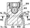
图12是图11的骨头固定系统沿着平面XII-XII截取的截面图;Fig. 12 is a sectional view of the bone fixation system of Fig. 11 taken along plane XII-XII;
图13是根据本公开的骨头固定系统的另一个示例的截面图;13 is a cross-sectional view of another example of a bone fixation system according to the present disclosure;
图14是骨头固定系统的压缩元件的另一个示例的截面图。14 is a cross-sectional view of another example of a compression element of a bone fixation system.
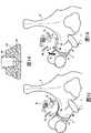
图15是示出图1的骨头固定系统在放到椎骨上的位置时的视图。FIG. 15 is a view showing the bone fixation system of FIG. 1 in position on a vertebra.
图16是示出图1的骨头固定系统在装配有图14的压缩元件并且放到椎骨上的位置时的视图。16 is a view showing the bone fixation system of FIG. 1 assembled with the compression element of FIG. 14 and positioned on a vertebra.
具体实施方式Detailed ways
在下面的详细描述中,涉及示出根据本公开的骨头固定系统的几个示例的附图。这些示例应当视为是示例性的而非限制性的,本发明的范围由所附权利要求给出。In the following detailed description, reference is made to the accompanying drawings illustrating several examples of bone fixation systems according to the present disclosure. These examples should be considered as illustrative and not restrictive, the scope of the invention being given by the appended claims.
骨头固定系统的示例在图1至3中示出。骨头固定系统10用于将杆5(其一部分在图1、3和15中示出)固定至骨头(参见图15)。骨头举例来说可以是脊椎的椎板或脊椎V的横突TP,如图15中所示。Examples of bone fixation systems are shown in Figures 1-3. The
骨头固定系统10包括:The
—适形细长元件7,比如绷带,其具有第一自由端部7a、第二自由端部7b以及其间的中间部分7c,所述中间部分7c适合于包围骨头(例如,横突TP);- a conformable
—主体12;-
—第一紧固设备或装置,用来将杆5的一部分紧固至主体12;以及- a first fastening device or means for fastening a part of the
—第二紧固设备或装置,用于将细长元件7的自由端部7a、7b紧固至主体12,所述第二紧固装置与第一紧固装置不同。- Second fastening means or means for fastening the
细长元件7可以是适形的任何适合材料,比如由金属、聚合材料或这两种材料的组合制成的带、线或绳。The
第二紧固装置包括可相对于主体12移动的压缩元件14,压缩元件14和主体12都限定夹持表面14c、12c,细长元件7的自由端部7a、7b可插入夹持表面14c、12c之间,所述自由端部7a、7b通过相对于主体12移动压缩元件14而夹持于所述夹持表面12c、14c之间。The second fastening means comprises a
主体12是空心的,从其下端至其上端沿着第一轴线Z延伸,并且包括:The
—主要部分12a,其具有向上延伸的侧壁13,侧壁13在其间限定沿着所述第一轴线Z延伸并且在其上端处开口到主体12外部的第一内部通道20;以及- the
—底部12b,其定位于主要部分12a的下面并且设置有延伸穿过底部12b的整个厚度并且与第一内部通道20相通的第二内部通道22。- The bottom 12b, which is positioned below the
主体12还包括第三和第四内部通道43、44,细长元件7的第一和第二自由端部7a、7b可分别插入穿过其中。每个内部通道43(44)延伸穿过主体12,具有两个端部43a、43b(44a、44b)并且在一端43a(44a)处在压缩元件14的前面开口且在另一端43b(44b)处开口到主体的外表面上,更准确地说开口到主体12的侧面上。第三和第四内部通道43、44形成用于细长元件7的自由端部7a、7b的导向装置。The
在示例中,第三和第四内部通道43、44分别沿着第三和第四轴线A、A`延伸,第三和第四轴线的每个相对于所述第一轴线Z形成优选地包括于0°和70°之间的锐角C。因而,医生更容易拉动细长元件7的端部7a、7b以将其拉紧。In the example, the third and fourth internal channels 43, 44 extend along third and fourth axes A, A' respectively, each of the third and fourth axes forming with respect to said first axis Z preferably comprising Acute angle C between 0° and 70°. Thus, it is easier for the physician to pull on the
另一方面,压缩元件14和主体12的夹持表面14c、12c在其间限定分别沿着第五和第六轴线B、B`延伸的第五和第六通道53、54,第五和第六轴线的每个相对于所述第一轴线Z形成钝角D。On the other hand, the
压缩元件14设置有螺纹孔24。所述锁定机构包括第一螺钉26,其具有头部26a以及带有外螺纹的轴26b。螺钉轴26b穿过第二内部通道22并且螺钉头部26a具有允许第一螺钉26受到驱动的轮廓28。在示例中,螺钉头26a是凹头,并且更具体地是能由举例来说艾伦内六角扳手驱动的六角凹头。The
在第一螺钉26受到驱动时,轴26b的外螺纹与压缩元件14的螺纹孔24相啮合并且螺钉头26a支承于底部12b的上表面12d上。因而,夹持表面14c、12c更靠近在一起并且端部7a、7b通过夹持于夹持表面14c、12c之间而锁定就位。When the first screw 26 is driven, the external thread of the shaft 26b engages the threaded hole 24 of the
现在转向用于将杆5的一部分紧固至主体12的第一紧固装置,开口30设置于侧壁13中(参见图2),以使得杆5的一部分可经由所述开口30装载入主体12,并且闭合元件32与主体12相接合以便将杆5的所述部分紧固至主体。Turning now to the first fastening means for fastening a part of the
在示例中,主体12设置有第一螺纹13b,用来与设置于闭合元件32上的第二螺纹32a相啮合,以使得杆5的所述部分可通过相对于主体12螺旋地移动闭合元件32而夹持于主体12和闭合元件之间。更准确地,在示例中,杆部分夹持于侧壁13的界定开口30底部的边缘13a与闭合元件32的下表面之间。In the example, the
在示例中,闭合元件32具有外螺纹32a,其与设置于侧壁13的内表面上的内螺纹13b相啮合。闭合元件32还包括用来驱动其旋转的凹头32b。In the example, the
骨头固定系统的另一个示例在图4中示出。图4的骨头固定系统110与图3的骨头固定系统的不同之处在于锁定机构。在图4中,底部12b的第二内部通道22设置有内螺纹123,并且压缩元件114具有形成所述锁定机构的突起部分114a。所述突起部分114a向上延伸,在其上端上具有允许压缩元件114受驱旋转的轮廓128,并且设置有与所述内螺纹123相啮合的外螺纹114b。Another example of a bone fixation system is shown in FIG. 4 . The
应当注意到,在图1-4的示例中,主体12的底部12b与主体12的主要部分12a成整体。在图5-7的示例中不是这种情况。It should be noted that in the example of FIGS. 1-4 , the bottom 12b of the
图5和6示出骨头固定系统210的另一个示例,其与图1-3的骨头固定系统的不同之处在于其包括具有没有彼此成整体的底部212b和主要部分212a的主体112。5 and 6 illustrate another example of a
在这个示例中,主体212的底部212b和主要部分212a通过球窝型连接而互连。In this example, the bottom 212b and
主要部分212a包括底壁250,底壁250设置有由上缘251a界定的通孔251。球窝型连接包括具有头部252a和轴252b的第二螺钉252。螺钉轴252b穿过所述通孔251并且穿过第二内部通道222。螺钉头252a具有支撑于所述上缘251a的凸形下表面252c以及允许第二螺钉252受驱的轮廓。举例来说,螺钉头252a可以是六角头或凹头的。螺钉头252a还具有凹形上表面252d。The
在杆5借助于第一紧固装置锁定就位时,杆5靠在第二螺钉252的凹形上表面252d上。更准确地,在闭合元件32向下螺旋时,闭合元件32在杆5上向下推,杆5又在螺钉252上向下推直到螺钉头252a的凸形下表面252c靠在通孔251的上缘251a上。由于螺钉头252a和上缘251a之间以及螺钉头252a和杆5之间的接触区域是有限的,所以螺钉头252a能相对于主体212的主要部分212a移动。The
上述结构是球窝型连接的一个示例,但是也能使用其他示例。The above structure is an example of a ball and socket type connection, but other examples can also be used.
球窝型连接允许主体212的底部212b与主要部分212a之间并且因而骨头和杆5之间的有限量的相对运动,从而提供或提高期望的动态稳定效果。The ball and socket type connection allows a limited amount of relative movement between the bottom 212b of the
除了螺钉头226a具有外部驱动轮廓228(代替内部驱动轮廓28),以及螺钉226设置有内螺纹孔227以外,底部212b与图3的底部12b基本上相同。The bottom 212b is substantially the same as the bottom 12b of FIG. 3 except that the
具有外螺纹的螺钉轴252b穿过第二内部通道222并且与螺纹孔227相啮合,以便将主体212的底部212b和主要部分212a连接在一起。A
具有球窝型连接的骨头固定系统310的另一个示例在图7中示出。在这个示例中,主体312的主要部分312a以及螺钉352与图6的那些部件(212a、252)相同,并且主体312的底部312b与图4的底部基本上相同,除了压缩元件328的突起部分314a具有外部驱动轮廓328以代替内部驱动轮廓128并且压缩元件314设置有内螺纹孔317以外。Another example of a
具有外螺纹的螺钉轴352b穿过第二内部通道322并且与螺纹孔327相啮合,以便将主体312的底部312b和主要部分312a连接在一起。A
在图6和7的这两个示例中,螺钉轴252b、352b穿过主要部分212a、312a的底壁250、350的通孔251、351并且穿过第二内部通道222、322且与压缩元件214、314相啮合。在图7中,其直接与压缩元件314相啮合,而在图6中,其经由螺钉226间接地与压缩元件214相啮合。In both examples of Figures 6 and 7, the
用来将骨头固定至杆5的骨头固定系统410、510、610、710的其他示例在图8至13中示出。它们中的每个包括:Further examples of
—适形的细长元件7,其具有第一自由端部7a、第二自由端部7b以及其间的中间部分7c,所述中间部分7c适合于包围所述骨头;- a conformable
—主体412、512、612、712;-
—第一紧固设备或装置,用来将杆5的一部分紧固至主体412、512、612、712;以及- first fastening means or means for fastening a part of the
—第二紧固设备或装置,用来将细长元件7的自由端部7a、7b紧固至主体412、512、612、712,所述第二紧固设备或装置与第一紧固设备或装置不同。- second fastening means or means for fastening the
在图8-12的系统中,用于将杆5的一部分紧固至主体412、512、612的第一紧固设备或装置与图1-4的相同,并且因此无需再次描述。In the system of Figs. 8-12, the first fastening means or means for fastening a part of the
在图8-13的全部示例中,第二紧固装置包括可相对于主体412、512、612移动的压缩元件,压缩元件和主体都限定细长元件7的自由端部7a、7b可插入其间的夹持表面,所述自由端部通过相对于主体移动压缩元件而夹持于所述夹持表面之间。In all the examples of figures 8-13, the second fastening means comprises a compression element movable relative to the
在图8的示例中,压缩元件414设置有螺纹414d,用来与设置于主体412上的另一个螺纹412a旋转啮合,以使得细长元件7的自由端部7a、7b可通过相对于主体412可螺旋地移动压缩元件414来夹持于主体412的压缩部分412e与压缩元件414之间。In the example of FIG. 8 , the
在这个示例中,压缩元件414是设置有内螺纹414d的螺母,并且主体412设置有外螺纹412a。在压缩元件414螺旋或松脱时,其移动更靠近或远离压缩部分412e。In this example, the
主体412包括:Subject 412 includes:
—压缩部分412e,其是在主体412的侧面上突出的凸缘,以及- a
—两个内部通道453、454,细长元件的第一和第二自由端部7a、7b可分别插入穿过其中,延伸穿过主体的第三和第四内部通道453、454的每个具有两个端部并且在一端处压缩元件414的前面开口且在另一端处开口到主体412的外表面上,并且更准确地开口到主体412的与接收杆5的另一个端面相反的端面上。- two
在压缩元件414与主体412可螺旋地相啮合时,其移动更靠近或远离压缩部分412e。As the
在图9的示例中,压缩元件514也是设置有内螺纹514d的螺母(参见图10),并且主体512也设置有外螺纹512a,但是在此情况下,压缩元件514没有直接与细长元件7相接触。实际上,压缩元件514与两个异型旋转零件515共同配合,所述异型零件可旋转地安装于(绕轴线R)设置于主体512的侧面上的凹陷512i中。在压缩元件514沿着主体512移动时,其推动凹陷512i中的旋转零件515,并且细长元件的每个自由端部7a、7b夹持于旋转零件515与凹陷512i的底壁之间。In the example of FIG. 9 the
在图11的示例中,压缩元件614是簧环并且主体具有用于接收细长元件的自由端部7a、7b以及压缩元件614的外周槽612i。自由端部7a、7b插入并且夹持于槽612i的底部与压缩元件614之间。In the example of FIG. 11 , the
压缩元件614也能是紧固轴环。
外周槽612i可沿着主体612的整个圆周或沿着其一部分延伸。The
在图13的示例中,第二紧固设备或装置包括螺钉764以及设置有通孔760的压缩元件714。骨头固定系统710的主体712设置有与所述通孔760对准的螺纹孔762。螺钉764的轴764b穿过所述通孔760并且与螺纹孔762可螺旋地相啮合。螺钉764的头部764a将靠在压缩元件714的上表面上。压缩元件714和主体712都限定细长元件的自由端部7a、7b可插入并且夹持于其间的夹持表面,所述自由端部通过将螺钉764螺旋入主体712而夹持。In the example of FIG. 13 , the second fastening device or means comprises a screw 764 and a compression element 714 provided with a through hole 760 . The main body 712 of the bone fixation system 710 is provided with a threaded hole 762 aligned with said through hole 760 . The shaft 764b of the screw 764 passes through the through hole 760 and is threadably engaged with the threaded hole 762 . The head 764a of the screw 764 will rest on the upper surface of the compression element 714 . Both the compression element 714 and the body 712 define a clamping surface into which the
在图13的示例中,第一紧固设备或装置包括用于接收杆5的一部分的座部分766,座部分766面向细长元件7的中间部分7c,杆5的所述部分通过拉紧细长元件7(例如,拉动细长元件7的自由端部7a、7b)而夹持于座部分766与细长元件的中间部分7c之间。优选地,座部分766是用于保持杆5的夹子。例如,座部分766由具有一定弹性的两个开口臂763界定,所述臂763部分地包围杆5。In the example of FIG. 13, the first fastening device or means comprises a seat portion 766 for receiving a part of the
现在转向图15,图1-3的骨头固定系统10示出为在脊椎V周围处于张紧位置。更准确地,细长元件7的中间部分7c包围脊椎的横突TP。Turning now to FIG. 15 , the
通过拉动细长元件7的端部,系统10的压缩元件14变得与横突TP相接触。By pulling the end of the
压缩元件14可由柔软材料制成,以避免损坏脊椎V和/或允许脊椎V和系统10之间并且因而脊椎V和杆5之间的有限量的相对运动,从而提供动态稳定效果。更具体地,与构成主体12并且优选地刚性的材料相比,压缩元件14的材料更柔软。The
为了提高缓冲效果和/或动态稳定效果,压缩元件14`可在其侧面上设置有至少一个外周槽19`。这种外周槽19`使得压缩元件14`更容易变形并且允许元件14`侧向地弯曲和轴向地压缩。因而允许脊椎V和系统10之间的有限量的相对运动(包括枢转运动),如由图16中的双箭头P所示。In order to increase the damping effect and/or the dynamic stabilization effect, the compression element 14' can be provided with at least one peripheral groove 19' on its side. Such a peripheral groove 19' makes it easier to deform the compression element 14' and allows the element 14' to bend laterally and compress axially. A limited amount of relative movement (including pivotal movement) between the vertebra V and the
Claims (15)
Translated fromChineseApplications Claiming Priority (3)
| Application Number | Priority Date | Filing Date | Title |
|---|---|---|---|
| EP09305720AEP2279707A1 (en) | 2009-07-31 | 2009-07-31 | Bone fixing system |
| EP09305720.6 | 2009-07-31 | ||
| PCT/EP2010/061085WO2011012690A1 (en) | 2009-07-31 | 2010-07-30 | Bone fixing system |
Publications (1)
| Publication Number | Publication Date |
|---|---|
| CN202821564Utrue CN202821564U (en) | 2013-03-27 |
Family
ID=41557586
Family Applications (1)
| Application Number | Title | Priority Date | Filing Date |
|---|---|---|---|
| CN2010900010422UExpired - Fee RelatedCN202821564U (en) | 2009-07-31 | 2010-07-30 | bone fixation system |
Country Status (4)
| Country | Link |
|---|---|
| US (4) | US9039708B2 (en) |
| EP (3) | EP2279707A1 (en) |
| CN (1) | CN202821564U (en) |
| WO (1) | WO2011012690A1 (en) |
Cited By (3)
| Publication number | Priority date | Publication date | Assignee | Title |
|---|---|---|---|---|
| CN109009385A (en)* | 2018-08-12 | 2018-12-18 | 苏州爱得科技发展股份有限公司 | A kind of dynamic state screw |
| CN109394322A (en)* | 2018-10-18 | 2019-03-01 | 温州医科大学附属第二医院、温州医科大学附属育英儿童医院 | A kind of extending internal fixation device of spine of transverse direction fix bone position |
| CN112022318A (en)* | 2020-09-22 | 2020-12-04 | 常州集硕医疗器械有限公司 | Spinal deformity growth fixation system and method |
Families Citing this family (62)
| Publication number | Priority date | Publication date | Assignee | Title |
|---|---|---|---|---|
| FR2890850B1 (en) | 2005-09-20 | 2009-04-17 | Abbott Spine Sa | VERTEBRAL FASTENING SYSTEM |
| US8100946B2 (en) | 2005-11-21 | 2012-01-24 | Synthes Usa, Llc | Polyaxial bone anchors with increased angulation |
| WO2007121271A2 (en) | 2006-04-11 | 2007-10-25 | Synthes (U.S.A) | Minimally invasive fixation system |
| EP2047813A1 (en)* | 2007-10-11 | 2009-04-15 | Abbott Spine | Bone fixing system and method of use |
| CA2694010C (en) | 2007-07-19 | 2015-04-21 | Synthes Usa, Llc | Clamps used for interconnecting a bone anchor to a rod |
| US9439681B2 (en) | 2007-07-20 | 2016-09-13 | DePuy Synthes Products, Inc. | Polyaxial bone fixation element |
| WO2010014119A1 (en) | 2008-07-29 | 2010-02-04 | Synthes (U.S.A) | Crimp with an insert to hold a cable |
| JP5815407B2 (en) | 2008-09-12 | 2015-11-17 | ジンテス ゲゼルシャフト ミット ベシュレンクテル ハフツング | Spinal stabilization and guided fixation system |
| KR20110081208A (en) | 2008-09-29 | 2011-07-13 | 신세스 게엠바하 | Multi-Axis Bottom-Loading Screw and Rod Assemblies |
| CA2742399A1 (en) | 2008-11-03 | 2010-06-03 | Dustin M. Harvey | Uni-planar bone fixation assembly |
| KR20120013312A (en) | 2009-04-15 | 2012-02-14 | 신세스 게엠바하 | Orthodontic Connectors for Spinal Structures |
| CN102497828B (en) | 2009-05-20 | 2015-09-09 | 斯恩蒂斯有限公司 | What patient installed retracts part |
| CA2764841A1 (en) | 2009-06-17 | 2010-12-23 | Synthes Usa, Llc | Revision connector for spinal constructs |
| EP2279707A1 (en) | 2009-07-31 | 2011-02-02 | Zimmer Spine | Bone fixing system |
| EP2316363A1 (en) | 2009-10-27 | 2011-05-04 | Zimmer Spine | Bone holding device |
| US8535318B2 (en) | 2010-04-23 | 2013-09-17 | DePuy Synthes Products, LLC | Minimally invasive instrument set, devices and related methods |
| EP2422728B1 (en) | 2010-08-25 | 2013-01-30 | Zimmer Spine | Anchor for attachment to a bony structure |
| CN103717159B (en) | 2011-05-27 | 2016-08-17 | 新特斯有限责任公司 | Minimally Invasive Spinal Fixation System Including Vertebral Alignment Features |
| FR2976783B1 (en) | 2011-06-22 | 2014-05-09 | Medicrea International | MATERIAL OF VERTEBRAL OSTEOSYNTHESIS |
| WO2013003719A1 (en) | 2011-06-29 | 2013-01-03 | Biomet Microfixation, Llc | Locking mechanism to secure ends of an implantable fabric |
| EP2734135B1 (en) | 2011-07-21 | 2018-03-21 | Zimmer Spine | Spinal rod fixing device |
| US8636770B2 (en) | 2011-08-08 | 2014-01-28 | Zimmer Spine, Inc. | Bone anchoring device |
| WO2013040456A1 (en)* | 2011-09-14 | 2013-03-21 | Band-Lok, Llc | Tether clamp and implantation system |
| US8834523B2 (en)* | 2011-09-29 | 2014-09-16 | Smith & Nephew, Inc. | Attachment device to attach tissue graft |
| EP2747670A4 (en) | 2011-10-05 | 2015-06-24 | Mark A Dodson | Modular retractor and related method |
| EP2819646A4 (en)* | 2012-02-03 | 2015-09-23 | Ardavan Aslie | Spinal fusion system for osteoporotic vertebrae |
| FR2988992B1 (en)* | 2012-04-04 | 2015-03-20 | Medicrea International | MATERIAL OF VERTEBRAL OSTEOSYNTHESIS |
| EP2668921B1 (en)* | 2012-06-01 | 2015-08-12 | Zimmer Spine | Device for fixing a bony structure to a support member |
| US9642719B1 (en) | 2012-11-07 | 2017-05-09 | Costello Law Corporation | Spinal fusion system for osteoporotic vertebrae |
| US20140148854A1 (en) | 2012-11-28 | 2014-05-29 | Zimmer Spine, Inc. | Vertebral fixation system |
| EP2762095B1 (en) | 2013-01-31 | 2016-05-25 | Zimmer Spine | Device for fixing a bony structure to a support member |
| US10034692B2 (en)* | 2013-03-05 | 2018-07-31 | Globus Medical, Inc. | Elastic member clamps |
| US9675386B2 (en) | 2013-03-11 | 2017-06-13 | K2M, Inc. | Flexible fastening system |
| US10010359B2 (en) | 2013-03-15 | 2018-07-03 | Zimmer Biomet CMF and Thoracic, LLC | Sternal closure cerclage, plate implant and instrumentation |
| WO2014144479A1 (en) | 2013-03-15 | 2014-09-18 | Biomet Microfixation, Llc | Sternal closure cerclage, plate implant and instrumentation |
| US9820755B2 (en) | 2013-03-15 | 2017-11-21 | Zimmer Biomet CMF and Thoracic, LLC | Sternal closure cerclage, plate implant and instrumentation |
| FR3008305B1 (en)* | 2013-07-15 | 2015-08-07 | Cousin Biotech | IMPLANTABLE DEVICE, IN PARTICULAR FOR CORRECTING AT LEAST ONE VERTEBRAL LEVEL |
| US9693809B2 (en)* | 2014-03-20 | 2017-07-04 | Warsaw Orthopedic, Inc. | Spinal correction implant system and method |
| US9402666B2 (en)* | 2014-04-30 | 2016-08-02 | King Faisal Specialist Hospital & Research Centre | Vertebral fixation device |
| FR3035584B1 (en)* | 2015-04-29 | 2017-05-19 | Medicrea Int | MATERIAL OF VERTEBRAL OSTEOSYNTHESIS |
| US9924976B2 (en) | 2015-09-24 | 2018-03-27 | Warsaw Orthopedic, Inc. | Spinal implant system and method |
| FR3047657B1 (en)* | 2016-02-15 | 2018-02-09 | Backbone | INTERVERTEBRAL IMPLANT OF DYNAMIC STABILIZATION AND SURGICAL KIT INCORPORATING IT |
| US10874438B2 (en)* | 2016-07-13 | 2020-12-29 | Medos International Sarl | Bone anchor assemblies and related instrumentation |
| EP3490474A4 (en)* | 2016-07-26 | 2019-08-28 | Band-lok, LLC | ORTHOPEDIC IMPLANTS. |
| EP3525699B1 (en) | 2016-10-11 | 2023-07-26 | K2M, Inc. | Spinal implant |
| CN106491199A (en)* | 2016-10-27 | 2017-03-15 | 贾东林 | A kind of Orthopedic fixation device |
| US10307186B2 (en) | 2016-12-02 | 2019-06-04 | Nuvasive, Inc. | Surgical band clamp system |
| US10456174B2 (en) | 2017-07-31 | 2019-10-29 | Medos International Sarl | Connectors for use in systems and methods for reducing the risk of proximal junctional kyphosis |
| US10463403B2 (en) | 2017-07-31 | 2019-11-05 | Medos International Sarl | Systems and methods for reducing the risk of proximal junctional kyphosis using a bone anchor or other attachment point |
| US11051857B2 (en)* | 2017-08-10 | 2021-07-06 | Ortho Development Corporation | Tether clamping assemblies and related methods and apparatus |
| US11071569B2 (en) | 2017-08-10 | 2021-07-27 | Ortho Development Corporation | Nesting tether clamping assemblies and related methods and apparatus |
| EP3806762B1 (en)* | 2018-06-05 | 2024-05-22 | K2M, Inc. | Band clamp, band clamp assembly |
| US10568674B1 (en) | 2019-01-24 | 2020-02-25 | Syberspine Limited | Pedicle screws with integrated anchor for retaining artificial ligament tape used for posterior ligament reconstruction |
| WO2020159483A1 (en)* | 2019-01-29 | 2020-08-06 | Ortho Development Corporation | Tether clamping assemblies and related methods and apparatus |
| US10869696B2 (en)* | 2019-01-30 | 2020-12-22 | Medos International Sarl | Surgical device for spinal fixation |
| US11819255B2 (en) | 2019-10-07 | 2023-11-21 | Ortho Development Corporation | Tether tensioning instrumentation and related methods |
| US20210121203A1 (en)* | 2019-10-29 | 2021-04-29 | Globus Medical, Inc. | Sublaminar band clamp |
| US11771475B2 (en) | 2020-10-07 | 2023-10-03 | Globus Medical, Inc. | Systems and methods for surgical procedures using band clamp implants and tensioning instruments |
| US12213706B2 (en) | 2020-10-07 | 2025-02-04 | Globus Medical, Inc. | Systems and methods for surgical procedures using band clamp implants and tensioning instruments |
| US11974785B2 (en)* | 2020-10-16 | 2024-05-07 | Globus Medical, Inc | Band clamp implants |
| US12433644B2 (en) | 2022-11-17 | 2025-10-07 | Warsaw Orthopedic, Inc. | Multiaxial receivers with tether |
| US11877775B1 (en) | 2022-11-21 | 2024-01-23 | Warsaw Orthopedic, Inc. | Multiaxial receivers with tether |
Family Cites Families (40)
| Publication number | Priority date | Publication date | Assignee | Title |
|---|---|---|---|---|
| US2049361A (en) | 1934-10-27 | 1936-07-28 | Ericsson Ernst Axel Johan | Wire or ribbon tightening apparatus |
| US4269178A (en) | 1979-06-04 | 1981-05-26 | Keene James S | Hook assembly for engaging a spinal column |
| US4570618A (en) | 1983-11-23 | 1986-02-18 | Henry Ford Hospital | Intervertebral body wire stabilization |
| USRE36221E (en) | 1989-02-03 | 1999-06-01 | Breard; Francis Henri | Flexible inter-vertebral stabilizer as well as process and apparatus for determining or verifying its tension before installation on the spinal column |
| US5030220A (en) | 1990-03-29 | 1991-07-09 | Advanced Spine Fixation Systems Incorporated | Spine fixation system |
| US5190545A (en)* | 1991-08-27 | 1993-03-02 | Pfizer Hospital Products Group, Inc. | Cerclage wire positioning insert |
| US5282816A (en) | 1991-09-20 | 1994-02-01 | Milres Corporation | Apparatus for subligamentous endoscopic transverse carpal ligament release surgery |
| US5242446A (en)* | 1992-01-02 | 1993-09-07 | Acromed Corporation | Connector for a spinal column corrective device |
| US5304178A (en) | 1992-05-29 | 1994-04-19 | Acromed Corporation | Sublaminar wire |
| AU1967095A (en) | 1994-02-17 | 1995-09-04 | Surgical Accessories, Inc. | Fastener and tensioner for bone securing cable |
| FR2761590B1 (en) | 1997-04-04 | 1999-08-20 | Stryker France Sa | DEVICE FOR OSTEOSYNTHESIS OF THE RACHIS WITH ATTACHMENT OF DEAXED INTERVERTEBRAL ROD |
| US6053921A (en) | 1997-08-26 | 2000-04-25 | Spinal Concepts, Inc. | Surgical cable system and method |
| US5964769A (en) | 1997-08-26 | 1999-10-12 | Spinal Concepts, Inc. | Surgical cable system and method |
| US6179838B1 (en) | 1998-02-24 | 2001-01-30 | Daniel Fiz | Bone fixation arrangements and method |
| US6086590A (en) | 1999-02-02 | 2000-07-11 | Pioneer Laboratories, Inc. | Cable connector for orthopaedic rod |
| US6299613B1 (en) | 1999-04-23 | 2001-10-09 | Sdgi Holdings, Inc. | Method for the correction of spinal deformities through vertebral body tethering without fusion |
| SE0000327D0 (en) | 2000-01-31 | 2000-01-31 | Sven Olerud | Device for locking metal wire against metal bar and method for locking the same to be used in spinal surgery |
| US6514255B1 (en)* | 2000-02-25 | 2003-02-04 | Bret Ferree | Sublaminar spinal fixation apparatus |
| US6605091B1 (en) | 2000-06-30 | 2003-08-12 | Pioneer Laboratories, Inc. | Surgical cable assembly and method |
| GB0018826D0 (en) | 2000-08-02 | 2000-09-20 | Depuy Int Ltd | Improvements in and relating to fixings |
| US6524315B1 (en) | 2000-08-08 | 2003-02-25 | Depuy Acromed, Inc. | Orthopaedic rod/plate locking mechanism |
| US6277120B1 (en)* | 2000-09-20 | 2001-08-21 | Kevin Jon Lawson | Cable-anchor system for spinal fixation |
| AU2002239723B2 (en) | 2000-10-24 | 2004-08-26 | The Spineology Group, Llc | Tension band clip |
| EP1205152B1 (en)* | 2000-11-10 | 2004-09-29 | Lafitt, S.A. | Spinal column deformity correction device |
| US6695852B2 (en) | 2001-10-31 | 2004-02-24 | Spineology, Inc. | Tension tools for tension band clip |
| FR2842724B1 (en) | 2002-07-23 | 2005-05-27 | Spine Next Sa | VERTEBRAL FASTENING SYSTEM |
| FR2845269B1 (en) | 2002-10-07 | 2005-06-24 | Spine Next Sa | PLATE FASTENING SYSTEM |
| US7776067B2 (en)* | 2005-05-27 | 2010-08-17 | Jackson Roger P | Polyaxial bone screw with shank articulation pressure insert and method |
| FR2859376B1 (en) | 2003-09-04 | 2006-05-19 | Spine Next Sa | SPINAL IMPLANT |
| FR2884135B1 (en)* | 2005-04-07 | 2007-06-22 | Abbott Spine Sa | INTERVERTEBRAL IMPLANT FOR LOMBO-SACRED JOINT |
| FR2890850B1 (en) | 2005-09-20 | 2009-04-17 | Abbott Spine Sa | VERTEBRAL FASTENING SYSTEM |
| FR2890851B1 (en) | 2005-09-21 | 2008-06-20 | Abbott Spine Sa | ANCILLARY TO TENSION A FLEXIBLE LINK. |
| US20070191844A1 (en)* | 2006-01-31 | 2007-08-16 | Sdgi Holdings, Inc. | In-series, dual locking mechanism device |
| EP2047813A1 (en) | 2007-10-11 | 2009-04-15 | Abbott Spine | Bone fixing system and method of use |
| ATE536824T1 (en) | 2007-10-23 | 2011-12-15 | Zimmer Spine | FASTENING DEVICES AND STABILIZATION SYSTEMS WITH THESE FASTENING DEVICES |
| US8128635B2 (en) | 2007-10-23 | 2012-03-06 | Zimmer Spine S.A.S. | Bone fixation tensioning tool and method |
| US20090192548A1 (en)* | 2008-01-25 | 2009-07-30 | Jeon Dong M | Pedicle-laminar dynamic spinal stabilization device |
| US20090248077A1 (en) | 2008-03-31 | 2009-10-01 | Derrick William Johns | Hybrid dynamic stabilization |
| FR2931654B1 (en) | 2008-05-27 | 2011-12-16 | Medicrea International | MATERIAL OF VERTEBRAL OSTEOSYNTHESIS |
| EP2279707A1 (en) | 2009-07-31 | 2011-02-02 | Zimmer Spine | Bone fixing system |
- 2009
- 2009-07-31EPEP09305720Apatent/EP2279707A1/ennot_activeWithdrawn
- 2010
- 2010-07-30CNCN2010900010422Upatent/CN202821564U/ennot_activeExpired - Fee Related
- 2010-07-30EPEP10736744.3Apatent/EP2459087B1/ennot_activeNot-in-force
- 2010-07-30EPEP15174582.5Apatent/EP3045128B1/ennot_activeNot-in-force
- 2010-07-30WOPCT/EP2010/061085patent/WO2011012690A1/enactiveApplication Filing
- 2010-07-30USUS13/384,180patent/US9039708B2/ennot_activeExpired - Fee Related
- 2015
- 2015-04-24USUS14/695,863patent/US9668774B2/enactiveActive
- 2017
- 2017-05-10USUS15/591,904patent/US9861391B2/enactiveActive
- 2017-11-30USUS15/826,940patent/US10512486B2/ennot_activeExpired - Fee Related
Cited By (3)
| Publication number | Priority date | Publication date | Assignee | Title |
|---|---|---|---|---|
| CN109009385A (en)* | 2018-08-12 | 2018-12-18 | 苏州爱得科技发展股份有限公司 | A kind of dynamic state screw |
| CN109394322A (en)* | 2018-10-18 | 2019-03-01 | 温州医科大学附属第二医院、温州医科大学附属育英儿童医院 | A kind of extending internal fixation device of spine of transverse direction fix bone position |
| CN112022318A (en)* | 2020-09-22 | 2020-12-04 | 常州集硕医疗器械有限公司 | Spinal deformity growth fixation system and method |
Also Published As
| Publication number | Publication date |
|---|---|
| US9039708B2 (en) | 2015-05-26 |
| US20180078285A1 (en) | 2018-03-22 |
| US9861391B2 (en) | 2018-01-09 |
| EP2279707A1 (en) | 2011-02-02 |
| US20120130373A1 (en) | 2012-05-24 |
| EP2459087A1 (en) | 2012-06-06 |
| WO2011012690A1 (en) | 2011-02-03 |
| EP3045128B1 (en) | 2017-11-29 |
| US9668774B2 (en) | 2017-06-06 |
| US20150223845A1 (en) | 2015-08-13 |
| US20170238970A1 (en) | 2017-08-24 |
| EP3045128A1 (en) | 2016-07-20 |
| EP2459087B1 (en) | 2015-07-29 |
| US10512486B2 (en) | 2019-12-24 |
Similar Documents
| Publication | Publication Date | Title |
|---|---|---|
| CN202821564U (en) | bone fixation system | |
| US9993274B2 (en) | Bone fixing system and method of use | |
| US11607251B2 (en) | Orthopedic tethered implants and system | |
| US8128635B2 (en) | Bone fixation tensioning tool and method | |
| US9427263B2 (en) | Device for fixing a bony structure to a support member | |
| US20150073481A1 (en) | Fixing devices and stabilization systems using said fixing devices | |
| US8740947B2 (en) | Multiple lead bone fixation apparatus | |
| US20040024411A1 (en) | Compressor for use in minimally invasive surgery | |
| AU2014208200A1 (en) | Bone fixing system and method of use |
Legal Events
| Date | Code | Title | Description |
|---|---|---|---|
| C14 | Grant of patent or utility model | ||
| GR01 | Patent grant | ||
| CF01 | Termination of patent right due to non-payment of annual fee | Granted publication date:20130327 Termination date:20180730 | |
| CF01 | Termination of patent right due to non-payment of annual fee |