CN202786257U - Exhaust filtration device for bioreactor - Google Patents
Exhaust filtration device for bioreactorDownload PDFInfo
- Publication number
- CN202786257U CN202786257UCN2011205796156UCN201120579615UCN202786257UCN 202786257 UCN202786257 UCN 202786257UCN 2011205796156 UCN2011205796156 UCN 2011205796156UCN 201120579615 UCN201120579615 UCN 201120579615UCN 202786257 UCN202786257 UCN 202786257U
- Authority
- CN
- China
- Prior art keywords
- exhaust
- filtration apparatus
- housing
- filtration
- filter
- Prior art date
- Legal status (The legal status is an assumption and is not a legal conclusion. Google has not performed a legal analysis and makes no representation as to the accuracy of the status listed.)
- Expired - Lifetime
Links
- 238000001914filtrationMethods0.000titleclaimsdescription28
- 230000002209hydrophobic effectEffects0.000claimsdescription8
- 239000007788liquidSubstances0.000abstractdescription9
- 239000007789gasSubstances0.000description41
- XLYOFNOQVPJJNP-UHFFFAOYSA-NwaterSubstancesOXLYOFNOQVPJJNP-UHFFFAOYSA-N0.000description10
- 238000009833condensationMethods0.000description8
- 230000005494condensationEffects0.000description8
- 239000003570airSubstances0.000description6
- 230000005484gravityEffects0.000description6
- 238000004519manufacturing processMethods0.000description5
- 239000002826coolantSubstances0.000description4
- 238000012258culturingMethods0.000description3
- 229920002457flexible plasticPolymers0.000description3
- 239000000463materialSubstances0.000description3
- 238000000034methodMethods0.000description3
- 230000005855radiationEffects0.000description3
- FAPWRFPIFSIZLT-UHFFFAOYSA-MSodium chlorideChemical compound[Na+].[Cl-]FAPWRFPIFSIZLT-UHFFFAOYSA-M0.000description2
- 230000036512infertilityEffects0.000description2
- 238000009434installationMethods0.000description2
- 230000035515penetrationEffects0.000description2
- 239000011148porous materialSubstances0.000description2
- 239000000443aerosolSubstances0.000description1
- 238000013019agitationMethods0.000description1
- 239000012080ambient airSubstances0.000description1
- 230000000903blocking effectEffects0.000description1
- 238000004113cell cultureMethods0.000description1
- 239000006285cell suspensionSubstances0.000description1
- 239000011248coating agentSubstances0.000description1
- 238000000576coating methodMethods0.000description1
- 238000010276constructionMethods0.000description1
- 239000000110cooling liquidSubstances0.000description1
- 238000003851corona treatmentMethods0.000description1
- 230000001419dependent effectEffects0.000description1
- 238000010894electron beam technologyMethods0.000description1
- 230000002070germicidal effectEffects0.000description1
- 239000012633leachableSubstances0.000description1
- 239000012528membraneSubstances0.000description1
- 239000002207metaboliteSubstances0.000description1
- 238000001471micro-filtrationMethods0.000description1
- 238000009832plasma treatmentMethods0.000description1
- 229920003023plasticPolymers0.000description1
- 230000000717retained effectEffects0.000description1
- 229920006395saturated elastomerPolymers0.000description1
- 239000011780sodium chlorideSubstances0.000description1
- 230000001954sterilising effectEffects0.000description1
- 238000011282treatmentMethods0.000description1
Images


Classifications
- B—PERFORMING OPERATIONS; TRANSPORTING
- B01—PHYSICAL OR CHEMICAL PROCESSES OR APPARATUS IN GENERAL
- B01D—SEPARATION
- B01D46/00—Filters or filtering processes specially modified for separating dispersed particles from gases or vapours
- B01D46/0039—Filters or filtering processes specially modified for separating dispersed particles from gases or vapours with flow guiding by feed or discharge devices
- C—CHEMISTRY; METALLURGY
- C12—BIOCHEMISTRY; BEER; SPIRITS; WINE; VINEGAR; MICROBIOLOGY; ENZYMOLOGY; MUTATION OR GENETIC ENGINEERING
- C12M—APPARATUS FOR ENZYMOLOGY OR MICROBIOLOGY; APPARATUS FOR CULTURING MICROORGANISMS FOR PRODUCING BIOMASS, FOR GROWING CELLS OR FOR OBTAINING FERMENTATION OR METABOLIC PRODUCTS, i.e. BIOREACTORS OR FERMENTERS
- C12M29/00—Means for introduction, extraction or recirculation of materials, e.g. pumps
- C12M29/04—Filters; Permeable or porous membranes or plates, e.g. dialysis
- B—PERFORMING OPERATIONS; TRANSPORTING
- B01—PHYSICAL OR CHEMICAL PROCESSES OR APPARATUS IN GENERAL
- B01D—SEPARATION
- B01D46/00—Filters or filtering processes specially modified for separating dispersed particles from gases or vapours
- B01D46/52—Particle separators, e.g. dust precipitators, using filters embodying folded corrugated or wound sheet material
- B01D46/521—Particle separators, e.g. dust precipitators, using filters embodying folded corrugated or wound sheet material using folded, pleated material
- C—CHEMISTRY; METALLURGY
- C12—BIOCHEMISTRY; BEER; SPIRITS; WINE; VINEGAR; MICROBIOLOGY; ENZYMOLOGY; MUTATION OR GENETIC ENGINEERING
- C12M—APPARATUS FOR ENZYMOLOGY OR MICROBIOLOGY; APPARATUS FOR CULTURING MICROORGANISMS FOR PRODUCING BIOMASS, FOR GROWING CELLS OR FOR OBTAINING FERMENTATION OR METABOLIC PRODUCTS, i.e. BIOREACTORS OR FERMENTERS
- C12M37/00—Means for sterilizing, maintaining sterile conditions or avoiding chemical or biological contamination
- C12M37/02—Filters
Landscapes
- Chemical & Material Sciences (AREA)
- Health & Medical Sciences (AREA)
- Life Sciences & Earth Sciences (AREA)
- Organic Chemistry (AREA)
- Zoology (AREA)
- Engineering & Computer Science (AREA)
- Bioinformatics & Cheminformatics (AREA)
- Wood Science & Technology (AREA)
- Sustainable Development (AREA)
- Microbiology (AREA)
- Biotechnology (AREA)
- Biomedical Technology (AREA)
- Biochemistry (AREA)
- General Engineering & Computer Science (AREA)
- General Health & Medical Sciences (AREA)
- Genetics & Genomics (AREA)
- Chemical Kinetics & Catalysis (AREA)
- Molecular Biology (AREA)
- Apparatus Associated With Microorganisms And Enzymes (AREA)
- Micro-Organisms Or Cultivation Processes Thereof (AREA)
- Filtering Of Dispersed Particles In Gases (AREA)
Abstract
Translated fromChinese
Description
Translated fromChinese技术领域technical field
本实用新型涉及用于培养细胞的生物反应器,并且更具体而言,涉及用于生物反应器的排气过滤器。本实用新型还涉及在生物反应器中培养细胞。 The utility model relates to a bioreactor for culturing cells, and more specifically, relates to an exhaust filter for the bioreactor. The utility model also relates to culturing cells in the bioreactor. the
背景技术Background technique
在生物反应器中培养细胞的期间,持续地将空气和/或其它气体供应给反应器,并且通过排气端口来移除余量以及来自细胞的气态代谢物。为了确保培养的无菌性,排气线路配备有杀菌级过滤器,其中,过滤介质可典型地为0.1微米-0.2微米的疏水性微滤膜。由于排气流是温暖的且水份饱和,所以存在这样的巨大风险:水份在过滤介质上冷凝,从而阻塞通过过滤器的气体流。 During the cultivation of cells in a bioreactor, air and/or other gases are continuously supplied to the reactor, and excess and gaseous metabolites from the cells are removed through the exhaust port. In order to ensure the sterility of the culture, the exhaust line is equipped with a sterilizing grade filter, wherein the filter medium can typically be a hydrophobic microfiltration membrane of 0.1 micron to 0.2 micron. Since the exhaust stream is warm and saturated with water, there is a significant risk that water will condense on the filter media, blocking the flow of gas through the filter. the
已经描述了若干种解决方案,其中在过滤器之前将水冷式冷凝器置于排气线路中(US 5,443,985;US 6,133,021;US 7,425,441),或者在过滤介质之前将水冷式冷凝器结合到过滤壳体中(2011/0076759)。然后任何水份均被冷凝,并且冷凝物可通过重力流来流回到生物反应器,并且因而避免液体冷凝物和过滤介质之间有任何接触。但是使用水冷式冷凝器是复杂的,因为必须通过管道来供应水,管道必须充分地固定到冷凝器和排水管上,以便避免任何泄漏。另外,水冷式冷凝器制造起来复杂,因为需要双壁式容器或具有内部管道和通过壁的管道端口的容器。这是缺陷,特别是对于在其中使用低成本的一次性塑料构件是非常合乎需要的一次性生物反应器中进行小规模至中等规模的细胞培养来说。 Several solutions have been described where a water-cooled condenser is placed in the exhaust line before the filter (US 5,443,985; US 6,133,021; US 7,425,441), or a water-cooled condenser is incorporated into the filter housing before the filter media Medium (2011/0076759). Any moisture is then condensed and the condensate can flow back to the bioreactor by gravity flow and thus avoid any contact between the liquid condensate and the filter media. But using a water-cooled condenser is complicated because the water must be supplied through pipes which must be sufficiently secured to the condenser and drain to avoid any leakage. In addition, water-cooled condensers are complicated to manufacture because of the need for double-walled vessels or vessels with internal piping and piping ports through the walls. This is a drawback, especially for small to medium scale cell culture in disposable bioreactors where the use of low cost disposable plastic components is highly desirable. the
因此,存在对可用于生物反应器中而不需要任何液冷式冷凝器的 排气过滤装置的需要。 Therefore, there is a need for an exhaust filtration device that can be used in bioreactors without requiring any liquid cooled condensers. the
实用新型内容Utility model content
本实用新型的一方面是要提供一种用于生物反应器的排气过滤装置,该排气过滤装置制造和使用简单,并且不需要任何液冷式冷凝器。这一点用这样的排气过滤装置来实现:该排气过滤装置包括具有过滤介质的壳体、气体入口和气体出口,并且进一步包括在所述气体入口和所述过滤介质之间的区域中从所述壳体的至少一个内壁延伸的多个肋。这个结构的一个优点在于,它适于作为单次使用装置来进行低成本生产,并且该装置易于操作。 An aspect of the present invention is to provide an exhaust filter device for a bioreactor, which is simple to manufacture and use, and does not require any liquid-cooled condenser. This is achieved with an exhaust gas filter device comprising a housing with a filter medium, a gas inlet and a gas outlet, and further comprising A plurality of ribs extend from at least one inner wall of the housing. An advantage of this structure is that it is suitable for low cost production as a single use device and the device is easy to handle. the
本实用新型的第二方面是要提供一种具有单次使用排气过滤装置的生物反应器。这一点用配备有这样的排气过滤装置的生物反应器来实现:该排气过滤装置包括具有过滤介质的壳体、气体入口和气体出口,并且进一步包括在所述气体入口和所述过滤介质之间的区域中从所述壳体的至少一个内壁延伸的多个肋。这个的一个优点在于,没有液体冷却剂线路,这有助于生物反应器的安装和组装。 A second aspect of the invention is to provide a bioreactor with a single-use exhaust air filter. This is achieved with a bioreactor equipped with an exhaust gas filter comprising a housing with a filter medium, a gas inlet and a gas outlet, and further comprising a filter medium between the gas inlet and the filter medium A plurality of ribs extending from at least one inner wall of the housing in the region therebetween. An advantage of this is that there are no liquid coolant lines, which facilitates installation and assembly of the bioreactor. the
在从属权利要求中描述了本实用新型的另外的适当的实施例。 Further suitable embodiments of the invention are described in the dependent claims. the
附图说明Description of drawings
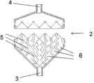
图1显示了根据本实用新型的排气过滤装置。 Fig. 1 shows an exhaust filter device according to the present invention. the
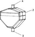
图2A、2B显示了用于图1的排气过滤装置的壳体的部件。 2A, 2B show components of a housing for the exhaust air filter device of FIG. 1 . the
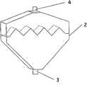
图3A、3B显示了根据本实用新型的排气过滤装置。 3A and 3B show the exhaust filter device according to the present invention. the
图4A、4B显示了根据本实用新型的、用于排气过滤装置的壳体的部件。 4A, 4B show components of a housing for an exhaust gas filter device according to the present invention. the
图5A、5B显示了根据本实用新型的、用于排气过滤装置的壳体的部件。 5A, 5B show components of a housing for an exhaust gas filter device according to the present invention. the
图6显示了具有根据本实用新型的排气过滤装置的生物反应器。 Fig. 6 shows a bioreactor with an exhaust filter device according to the present invention. the
具体实施方式Detailed ways
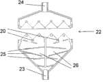
在图1、2A、2B、3A、3B、4A、4B、5A、5B所示出的第一方面,本实用新型公开了一种用于生物反应器的排气过滤装置,其包括具有过滤介质1的壳体2、12、22、气体入口3、13、23和气体出口4、14、24。壳体进一步包括在气体入口3、13、23和过滤介质1之间的区域中从壳体2、12、22的至少一个内壁延伸的至少两个肋5、15、25。过滤介质可恰当地延伸跨过壳体的内部容积的区段,从而限定两个隔室——一个在气体入口3、13、23和过滤介质1之间,并且一个在过滤介质1和气体出口4、14、24之间。过滤介质1的大体方向可在基本垂直于在气体入口3、13、23的中心和气体出口4、14、24的中心之间所划的直线或相对于该直线成大约60度至90度的角的平面上。肋5、15、25可与壳体的至少一个壁成一体,或者它们可单独制造和安装在壳体中。它们可沿基本垂直于壳体的至少一个内壁的方向延伸,或者它们可相对于内壁成角度。肋的优点在于,来自生物反应器的空气中的水份可在肋上冷凝,并且冷凝物由于重力而可流回到生物反应器。 In the first aspect shown in Figures 1, 2A, 2B, 3A, 3B, 4A, 4B, 5A, and 5B, the utility model discloses an exhaust filter device for a bioreactor, which includes a
在由图1、2A、2B、3A、3B、4A、4B、5A、5B示出的一些实施例中,肋在所述壳体的两个相对的内壁之间延伸。然后它们可在底部入口和过滤介质1之间限定多个通道6、16、26,使得从气体入口3、13、23流向过滤介质1的气体流可分成若干个子流。这会增加气体和肋表面之间的接触面积,并且改进冷凝。为了进一步增加接触面积以及因而改进冷凝,通道6、16、26可为曲折的,例如具有>1.1的平均变曲度,其中变曲度被定义为通道的长度除以通道的端部-端部的直线距离。平均变曲度可介于1.1和5之间,这一点可通过在壳体中具有弯曲的或成角度的肋来实现。通道6、26可为平行的,如图1、2A、2B和4A、4B中示出的那样,或者它们可形成具有图3A、3B中示出的分支点和/或重连点的通道16的互连网络。 In some embodiments illustrated by Figures 1, 2A, 2B, 3A, 3B, 4A, 4B, 5A, 5B, ribs extend between two opposing inner walls of the housing. They can then define a plurality of
在某些实施例中,肋5、15、25布置成连续或间断的Z字形型式。 图1和2A、2B中示出了连续的Z字形型式,其中肋5的节段相对于彼此以规则的型式成角度。图3A、3B中示出了间断的Z字形型式,其中单独的肋15相对于彼此以规则的型式成角度。Z字形型式中的角可为例如60度-120度,例如80度-100度。使用Z字形型式的优点在于,气体流反复地被偏转,从而导致与肋表面有改进的接触,并且因此导致有改进的冷凝。 In certain embodiments, the
在一些实施例中,壳体2、12、22是单壁式的。因此,不存在用于将液体冷却介质供应给排气过滤装置的布置。单壁式壳体不具有或者由于壳体壁的设计或者由于通过壳体的内部容积而引入管状回路而形成的任何双壁。具有单壁式壳体的优点在于其较容易制造和安装。另一个优点还在于,壳体和环境空气之间的热传递得到改进。壳体壁的平均厚度可为小于1mm,例如小于0.5mm,以进一步改进与周围空气的热传递。 In some embodiments, the
在某些实施例中,过滤介质1被打褶,以增加过滤面积。褶7可在相对于气体入口3、13、23和气体出口4、14、24之间的直线成60度-90度(例如80度-90度)的角的平面上延伸。这意味着当在气体出口在顶部处而气体入口在底部处的情况下排气过滤装置或多或少沿竖向运行时,褶支腿8相对于水平平面成角度,并且在过滤器中冷凝的任何水份均可由于重力而流向下部褶,其中冷凝物可从褶上滴下,并且由于重力而流回到生物反应器。 In some embodiments, the
在一些实施例中,打褶过滤介质的褶角9为20度-120度,例如30度-100度。低于120度或100度的褶角确保任何冷凝物如上面描述的那样有朝向下部褶的重力流,并且它还允许过滤介质面积有显著的增加。对于低于20度或30度的褶角,存在的风险是,任何冷凝物均可在褶支腿8之间形成水桥,这可导致阻塞过滤介质面积的一部分。 In some embodiments, the
在某些实施例中,多个褶,例如所有下部褶(面向气体入口的褶),由从壳体12、22的至少一个壁延伸的褶支承杆10、20支承。褶支承杆可具有适合褶的有角凹部。褶支承杆的一个优点在于,有助于安装 过滤介质,以及改进机械稳定性。褶支承杆的另一个优点在于可有助于使冷凝水份从下部褶滴下。 In certain embodiments, a plurality of pleats, for example all lower pleats (the pleats facing the gas inlet), are supported by
在一些实施例中,过滤介质是疏水性的。疏水性过滤介质不会被纯水弄湿,但是允许气体通过。可通过透水测试来评定疏水性特性,其中,通过施加的压力来迫使纯水通过过滤介质,并且记录透水所需的压力。0.20微米的过滤介质在透水压力高于大约1巴(100kPa)(例如高于大约3巴)的情况下可表示为疏水性的。使用疏水性过滤器的优点在于,携带在气体流中的气溶胶滴不会穿过过滤器。疏水性过滤器还较不易于由于水份的冷凝而被阻塞。可选择过滤器的孔径大小,以确保生物反应器包含物的无菌性。这典型地用具有低于大约0.25微米(例如0.05-0.20微米或0.1-0.22微米)的孔径大小的杀菌级过滤器来完成。 In some embodiments, the filter media is hydrophobic. Hydrophobic filter media are not wetted by pure water, but allow gases to pass through. Hydrophobic properties can be assessed by a water penetration test, in which pure water is forced through the filter media by applied pressure and the pressure required to break through is recorded. A 0.20 micron filter medium may be characterized as hydrophobic at a water penetration pressure above about 1 bar (100 kPa), such as above about 3 bar. The advantage of using a hydrophobic filter is that aerosol droplets entrained in the gas stream do not pass through the filter. Hydrophobic filters are also less prone to clogging due to condensation of moisture. The pore size of the filter can be selected to ensure the sterility of the bioreactor contents. This is typically accomplished with a germicidal grade filter having a pore size below about 0.25 microns (eg, 0.05-0.20 microns or 0.1-0.22 microns). the
在一些实施例中,肋和壳体的内壁的表面可为亲水性的,例如具有小于50度的均衡水接触角,以帮助任何水份的冷凝和排出。可通过诸如电晕放电或等离子体处理的处理或通过用亲水性材料涂覆表面来实现亲水性。 In some embodiments, the surfaces of the ribs and the inner walls of the housing may be hydrophilic, eg, have an equilibrium water contact angle of less than 50 degrees, to aid in the condensation and drainage of any moisture. Hydrophilicity can be achieved by treatments such as corona discharge or plasma treatment or by coating the surface with a hydrophilic material. the
在某些实施例中,排气过滤装置进一步包括夹持到壳体的外壁上的至少一个珀耳帖(peltier)元件和/或用于将至少一个珀耳帖元件夹持到壳体的外壁上的机构。将珀耳帖元件夹持到壳体上的优点在于,可在不应用任何液体冷却剂的情况下实现提高的冷凝速率。 In some embodiments, the exhaust gas filtering device further comprises at least one Peltier element clamped to the outer wall of the housing and/or for clamping the at least one Peltier element to the outer wall of the housing above institutions. An advantage of clamping the Peltier element to the housing is that an increased condensation rate can be achieved without the application of any liquid coolant. the
在图6所示出的第二方面,本实用新型公开了一种配备有上面描述的排气过滤装置31的生物反应器30。该生物反应器可为一次性生物反应器,并且可包括作为生物反应器容器的柔性塑料袋32和生物反应器气体入口35。排气过滤装置和气体入口两者可安装在柔性塑料袋的顶壁中的端口中。这种柔性塑料袋可安装在可动平台33上,可动平台通过绕着枢转轴线34的摇动动作来提供搅动作用。对摇动的柔性袋生物反应器使用描述的排气过滤装置的特别优点在于,没有任何液体冷却剂管道,这有助于生物反应器的设置和运行,因为不需要摇动的管道。柔性袋生物反应器通常还用于仅一次性构件,这强调对 具有低生产成本的排气过滤装置的需要。可作为预组装套件来供应袋32、过滤装置31、管道和其它一次性构件,可通过例如将它们暴露于伽马辐射或电子束辐射来对它们进行消毒。然后如果所有构件(包括排气过滤装置)均由抗辐射材料(即在暴露于25千戈瑞辐射剂量之后不会显著地退化以及在辐照之后不会产生不合需要的可浸出物的材料)制成,则这是有利的。 In the second aspect shown in FIG. 6 , the utility model discloses a bioreactor 30 equipped with the above-described exhaust filter device 31 . The bioreactor may be a disposable bioreactor and may include a flexible plastic bag 32 and a bioreactor gas inlet 35 as the bioreactor container. Both the exhaust filter and the gas inlet can be mounted in ports in the top wall of the flexible plastic bag. Such a flexible plastic bag can be mounted on a movable platform 33 which provides agitation by a rocking action about a pivot axis 34 . A particular advantage of using the described vent filter arrangement with a rocking flexible bag bioreactor is the absence of any liquid coolant piping, which facilitates the setup and operation of the bioreactor since no rocking piping is required. Flexible bag bioreactors are also typically used for single-use components only, which underscores the need for exhaust filtration devices with low production costs. The bag 32, filter device 31, tubing and other disposable components can be supplied as a pre-assembled kit, which can be sterilized by exposing them to gamma or electron beam radiation, for example. Then if all components, including the exhaust filter, are made of radiation resistant materials (i.e. materials that do not significantly degrade after exposure to a radiation dose of 25 kGy and do not produce undesirable leachables after irradiation) made, this is advantageous. the
在图6所示出的第三方面,本实用新型公开了一种在配备有上面描述的排气过滤装置的生物反应器中培养细胞的方法。 In a third aspect shown in FIG. 6 , the present invention discloses a method for culturing cells in a bioreactor equipped with the above-described exhaust filter device. the
在某些实施例中,来自生物反应器的水份进入排气过滤装置,并且在培养期间在该多个肋上冷凝。 In certain embodiments, moisture from the bioreactor enters the exhaust filter unit and condenses on the plurality of ribs during cultivation. the
在一些实施例中,细胞悬浮液体积(液体体积)小于100升,例如介于0.5升和20升之间。在小规模至中等规模的培养中,从生物反应器中带走的水份的量使其可由上面描述的一个排气过滤装置容易地处理。对于较大的培养,可能需要若干个装置。通过排气过滤装置的气体流率可小于2升/分钟,例如介于0.05升/分钟和1升/分钟之间。如果使用了若干个排气过滤装置,则各个装置中的流率可小于2升/分钟,例如介于0.05升/分钟和1升/分钟之间。 In some embodiments, the cell suspension volume (liquid volume) is less than 100 liters, eg, between 0.5 liters and 20 liters. In small to medium scale cultures, the amount of water carried away from the bioreactor is such that it can be easily treated by an exhaust filter as described above. For larger cultures, several devices may be required. The gas flow rate through the exhaust filter device may be less than 2 liters/minute, for example between 0.05 liters/minute and 1 liter/minute. If several exhaust gas filtering devices are used, the flow rate in each device may be less than 2 liters/minute, for example between 0.05 liters/minute and 1 liter/minute. the
在某些实施例中,没有对所述排气过滤装置应用冷却液体。这简化了运行。 In some embodiments, no cooling liquid is applied to the exhaust gas filtering device. This simplifies operation. the
在一些实施例中,排气过滤装置定位成气体出口4、14、24在气体入口3、13、23的上方,并且在所述气体入口和所述气体出口之间的直线相对于竖向平面为小于大约30度。排气过滤装置的这个大体竖向的定向有助于冷凝的水份在重力的作用下从肋和/或褶上流下且流回到生物反应器。 In some embodiments, the exhaust filter arrangement is positioned such that the
实例example
实例1 Example 1
测试装备: Test equipment:
WAVE生物反应器系统2/10仪器(瑞典的GE Healthcare Bio-Sciences)、五个2升CellbagTM柔性袋(瑞典的GE Healthcare Bio-Sciences),各个柔性袋均装有1升的9毫克/毫升的NaCl,并且配备有空气入口以及在气体出口中的排气过滤装置。
Wave仪器的参数设置为: The parameters of the Wave instrument are set to:

在开始时对干的过滤装置称重,并且在Wave仪器中运行23小时之后再次对其称重。 Dry filter units were initially weighed and weighed again after 23 hours in the Wave instrument. the
比较冷凝物的重量与来自在对袋供应具有平的过滤介质且没有肋的标准排气过滤器的情况下设置的基准的重量。对两个过滤装置样机进行了评价,根据图5A、5B的一个和根据图4A、4B的一个。在表1中显示了结合。 The weight of the condensate was compared to the weight from a benchmark set when the bag was supplied with a standard exhaust filter with flat filter media and no ribs. Two filter device prototypes were evaluated, one according to Figures 5A, 5B and one according to Figures 4A, 4B. Binding is shown in Table 1. the
表1。 Table 1. the
显然,保留在过滤器中的冷凝物的量被新的结构大大地降低。 Clearly, the amount of condensate retained in the filter is greatly reduced by the new construction. the
本书面描述使用实例来公开本实用新型,包括最佳模式,并且还使本领域任何技术人员能够实践本实用新型,包括制造和使用任何装置或系统,以及执行任何结合的方法。本实用新型的可授予专利的范 围由权利要求限定,并且可包括本领域技术人员想到的其它实例。如果这样的其它实例具有不异于权利要求的字面语言的结构元素,或者如果它们包括与权利要求的字面语言无实质性差异的等效结构元素,则这样的其它实例意图处于权利要求的范围之内。指出了关于一个实施例所描述的任何特征也可与描述的实施例中的任何其它实施例的一个或多个特征结合起来使用。 This written description uses examples to disclose the invention, including the best mode, and also to enable any person skilled in the art to practice the invention, including making and using any devices or systems and performing any incorporated methods. The patentable scope of the invention is defined by the claims, and may include other examples that occur to those skilled in the art. Such other examples are intended to be within the scope of the claims if they have structural elements that do not differ from the literal language of the claims, or if they include equivalent structural elements with insubstantial differences from the literal language of the claims Inside. It is pointed out that any feature described in relation to one embodiment may also be used in combination with one or more features of any other of the described embodiments. the
Claims (16)
Applications Claiming Priority (2)
| Application Number | Priority Date | Filing Date | Title |
|---|---|---|---|
| SE1150790-2 | 2011-08-31 | ||
| SE1150790 | 2011-08-31 |
Publications (1)
| Publication Number | Publication Date |
|---|---|
| CN202786257Utrue CN202786257U (en) | 2013-03-13 |
Family
ID=47756641
Family Applications (1)
| Application Number | Title | Priority Date | Filing Date |
|---|---|---|---|
| CN2011205796156UExpired - LifetimeCN202786257U (en) | 2011-08-31 | 2011-12-31 | Exhaust filtration device for bioreactor |
Country Status (5)
| Country | Link |
|---|---|
| US (1) | US9795909B2 (en) |
| EP (1) | EP2751253B1 (en) |
| JP (1) | JP6186358B2 (en) |
| CN (1) | CN202786257U (en) |
| WO (1) | WO2013032392A1 (en) |
Cited By (2)
| Publication number | Priority date | Publication date | Assignee | Title |
|---|---|---|---|---|
| CN108026496A (en)* | 2015-10-01 | 2018-05-11 | 通用电气健康护理生物科学股份公司 | Filter holding device |
| CN112823203A (en)* | 2018-10-17 | 2021-05-18 | 环球生命科技咨询美国有限责任公司 | Bioreactor system |
Families Citing this family (8)
| Publication number | Priority date | Publication date | Assignee | Title |
|---|---|---|---|---|
| US8455242B2 (en) | 2010-02-22 | 2013-06-04 | Hyclone Laboratories, Inc. | Mixing system with condenser |
| EP3041927B1 (en) | 2013-09-06 | 2018-02-28 | GE Healthcare Bio-Sciences AB | Cell culture bag with internal dialysis membrane |
| WO2015142405A1 (en)* | 2014-03-21 | 2015-09-24 | Life Technologies Corporation | Gas filter systems for fluid processing systems |
| JP6585615B2 (en) | 2014-03-21 | 2019-10-02 | ライフ テクノロジーズ コーポレイション | Condenser system for fluid treatment system |
| US9457306B2 (en) | 2014-10-07 | 2016-10-04 | Life Technologies Corporation | Regulated vacuum off-gassing of gas filter for fluid processing system and related methods |
| US9920292B2 (en) | 2015-08-31 | 2018-03-20 | General Electric Company | System and method for initiating a cell culture |
| WO2017116910A1 (en) | 2015-12-29 | 2017-07-06 | Life Technologies Corporation | Flexible bioprocessing container with partial dividing partition |
| CN108753566B (en)* | 2018-04-23 | 2024-03-29 | 苏州欧飞纳米科技有限公司 | Heating device for gas filtration system |
Family Cites Families (40)
| Publication number | Priority date | Publication date | Assignee | Title |
|---|---|---|---|---|
| US3992177A (en)* | 1975-05-28 | 1976-11-16 | Carl Welteroth | Multi-action particle separator |
| US4007026A (en)* | 1975-08-13 | 1977-02-08 | Fmc Corporation | Compact dust filter system |
| US4135900A (en)* | 1977-05-31 | 1979-01-23 | American Air Filter Company, Inc. | Gas filter device |
| US4512891A (en)* | 1982-11-16 | 1985-04-23 | Donaldson Company, Inc. | Pleated filter element with controlled expansibility and frame therefor |
| LU84927A1 (en)* | 1983-07-22 | 1985-04-17 | Cockerill Mech Ind Sa | HIGH TEMPERATURE GAS FLUID FILTERING DEVICE |
| US5000768A (en)* | 1990-02-01 | 1991-03-19 | Hwang Feng Lin | Filtering and absorbing device for vehicle discharge pipe |
| US5174896A (en)* | 1990-06-25 | 1992-12-29 | Harmsco, Inc. | Filtering system utilizing rotational flow and angled pleated filter media and method for making slanted pleated filter media |
| JP3006908U (en)* | 1994-07-19 | 1995-01-31 | 有限会社名技工業 | Indoor booster |
| US5531892A (en)* | 1995-09-15 | 1996-07-02 | Minnesota Mining And Manufacturing Company | Zigzag filter media and frame having triangular pleat stabilizing elements |
| US5783086A (en)* | 1995-09-29 | 1998-07-21 | W. L. Gore & Associates, Inc. | Filter for a wet/dry vacuum cleaner for wet material collection |
| US5800586A (en)* | 1996-11-08 | 1998-09-01 | Johns Manville International, Inc. | Composite filter media |
| US5810898A (en)* | 1997-05-22 | 1998-09-22 | Superior Fibers, Inc. | Nestable pleated filter |
| US6387260B1 (en)* | 1997-08-21 | 2002-05-14 | Electrophor, Inc. | Filtration device for liquid purification |
| SE512385C2 (en)* | 1998-03-25 | 2000-03-06 | Camfil Ab | Air filter of pleated filter material and methods for its manufacture |
| US5912368A (en) | 1998-03-30 | 1999-06-15 | Ford Motor Company | Air filter assembly for automotive fuel vapor recovery system |
| US6159318A (en)* | 1998-10-21 | 2000-12-12 | Aaf International, Inc. | Method for forming fibrous filter media, filter units and product |
| AT3433U3 (en)* | 1999-12-30 | 2001-04-25 | Avl List Gmbh | SYSTEM FOR CONDUCTING LIQUID MEDIA AND FILTER DEVICE FOR USE IN THIS SYSTEM |
| US6328442B1 (en)* | 2000-01-31 | 2001-12-11 | Hewlett-Packard Company | Particulate filtering muffler |
| DE10010710A1 (en)* | 2000-03-04 | 2001-09-06 | Mann & Hummel Filter | Filter element |
| US7104403B1 (en)* | 2000-12-20 | 2006-09-12 | The Unimin Corporation | Static two stage air classifier |
| JP2003236323A (en)* | 2002-02-20 | 2003-08-26 | Kobe Kosakusho:Kk | Mist separation and recovery device |
| US6817940B2 (en)* | 2002-06-03 | 2004-11-16 | Pfannenberg Gmbh | Airflow unit |
| US6936086B2 (en)* | 2002-09-11 | 2005-08-30 | Planar Systems, Inc. | High conductivity particle filter |
| JP2005098657A (en)* | 2003-09-26 | 2005-04-14 | Zexel Valeo Climate Control Corp | Air conditioner and its filter unit |
| US7137390B2 (en)* | 2004-01-23 | 2006-11-21 | Ric Investments, Llc. | Liquid absorbing filter assembly and system using same |
| EP1773976B2 (en) | 2004-06-04 | 2020-01-01 | Global Life Sciences Solutions USA LLC | Disposable bioreactor systems and methods |
| JP2008082285A (en)* | 2006-09-28 | 2008-04-10 | Techno Takatsuki Co Ltd | Air pump dust collection mechanism |
| US7632339B2 (en)* | 2006-12-18 | 2009-12-15 | General Electric Company | Moisture removal apparatus and method |
| DE102008025968B4 (en) | 2008-05-30 | 2014-08-21 | Sartorius Stedim Biotech Gmbh | Bioreactor with condenser |
| DE102008027638A1 (en)* | 2008-06-06 | 2009-12-10 | Sann, Heiner, Dr. | Bioreactor effluent air is discharged to flexible disposal bag with ports, lifting points and cooling assembly |
| DE102009003972B4 (en) | 2009-01-07 | 2011-04-28 | Sartorius Stedim Biotech Gmbh | Exhaust system for bioreactors |
| DE102009011568B4 (en)* | 2009-03-06 | 2010-12-23 | Mann + Hummel Gmbh | Filter device for a motor vehicle |
| US8052768B2 (en)* | 2009-05-21 | 2011-11-08 | Ford Global Technologies, Llc | Air filtration apparatus |
| JP2012531930A (en) | 2009-07-06 | 2012-12-13 | ジェネンテック, インコーポレイテッド | Eukaryotic cell culture method |
| AU2010300549B2 (en)* | 2009-09-30 | 2014-09-11 | Ge Healthcare Bio-Sciences Corp | Disposable bioreactor condenser bag and filter heater |
| US8455242B2 (en)* | 2010-02-22 | 2013-06-04 | Hyclone Laboratories, Inc. | Mixing system with condenser |
| US8132559B2 (en)* | 2010-07-15 | 2012-03-13 | Ford Global Technologies, Llc | Water/air separator |
| US8382711B2 (en)* | 2010-12-29 | 2013-02-26 | Baxter International Inc. | Intravenous pumping air management systems and methods |
| JP2014522294A (en)* | 2011-04-13 | 2014-09-04 | ジーエフディー ファブリックス,インク. | Filter elements for fluid filtration systems |
| US9295746B2 (en)* | 2013-12-05 | 2016-03-29 | Rgf Environmental Group, Inc. | Add on filter for package air handling unit |
- 2011
- 2011-12-31CNCN2011205796156Upatent/CN202786257U/ennot_activeExpired - Lifetime
- 2012
- 2012-08-29EPEP12829000.4Apatent/EP2751253B1/enactiveActive
- 2012-08-29JPJP2014528328Apatent/JP6186358B2/enactiveActive
- 2012-08-29WOPCT/SE2012/050912patent/WO2013032392A1/enactiveApplication Filing
- 2012-08-29USUS14/241,550patent/US9795909B2/enactiveActive
Cited By (4)
| Publication number | Priority date | Publication date | Assignee | Title |
|---|---|---|---|---|
| CN108026496A (en)* | 2015-10-01 | 2018-05-11 | 通用电气健康护理生物科学股份公司 | Filter holding device |
| CN108026496B (en)* | 2015-10-01 | 2022-07-26 | 思拓凡瑞典有限公司 | filter holder |
| CN112823203A (en)* | 2018-10-17 | 2021-05-18 | 环球生命科技咨询美国有限责任公司 | Bioreactor system |
| CN112823203B (en)* | 2018-10-17 | 2024-05-24 | 环球生命科技咨询美国有限责任公司 | Bioreactor system |
Also Published As
| Publication number | Publication date |
|---|---|
| WO2013032392A1 (en) | 2013-03-07 |
| US9795909B2 (en) | 2017-10-24 |
| JP2014525264A (en) | 2014-09-29 |
| JP6186358B2 (en) | 2017-08-23 |
| EP2751253B1 (en) | 2016-11-23 |
| US20140193883A1 (en) | 2014-07-10 |
| EP2751253A1 (en) | 2014-07-09 |
| EP2751253A4 (en) | 2015-07-15 |
Similar Documents
| Publication | Publication Date | Title |
|---|---|---|
| CN202786257U (en) | Exhaust filtration device for bioreactor | |
| US20140287512A1 (en) | Method of cultivating cells on microcarriers in a bag | |
| CN115029246B (en) | Filter retaining device | |
| CN107921327B (en) | Bioreactor Condenser | |
| BR112017013400B1 (en) | DOUBLE BAG SET FOR T-CELL CULTURE | |
| WO2014192432A1 (en) | Filter module and filter device | |
| CN113164873B (en) | Membrane distillation assembly and membrane distillation device | |
| CN111989391A (en) | Inflatable bioreactor and method of use | |
| CN113908579B (en) | System and method for condensing moisture in a bioreactor gas stream | |
| CN201244144Y (en) | Vertical lamellar flow bed | |
| US20190151803A1 (en) | Easily-assemblable diffusiophoretic water filtration device | |
| CN110734858A (en) | multi-mode three-dimensional perfusion type cell culture instrument | |
| CN207203114U (en) | A kind of quantitative filtering bactericidal unit | |
| CN204401001U (en) | Airborne particulate matter collection device in cell culture medium | |
| CN207702855U (en) | A kind of drying unit and Manufacture of medicinal slices of TCM system of the prepared slices of Chinese crude drugs | |
| EP1820530B1 (en) | Humidifier and use of the humidifier | |
| JP2010239916A (en) | Culture vessel spacer, culture device provided with the spacer, and observation method using the culture device | |
| CN105642120A (en) | Membrane distillation device | |
| CN206435055U (en) | A kind of filter using two-dimentional micro Nano material filter membrane | |
| EP4242289A1 (en) | Gas-permeable container, and culture apparatus and culture system each using same | |
| CN221036668U (en) | Sterile drying device for pharmaceutical appliance | |
| CN215901046U (en) | Fibroblast culture medium preparation device | |
| CN109318688A (en) | Vehicle air Humidifier | |
| CN104498356B (en) | Airborne particulate matter collection device in a kind of cell culture medium | |
| CN216978969U (en) | Biological aerosol killing performance evaluation system |
Legal Events
| Date | Code | Title | Description |
|---|---|---|---|
| C14 | Grant of patent or utility model | ||
| GR01 | Patent grant | ||
| CP01 | Change in the name or title of a patent holder | ||
| CP01 | Change in the name or title of a patent holder | Address after:uppsala Patentee after:Stoivan Sweden Limited Address before:uppsala Patentee before:GE HEALTHCARE BIO-SCIENCES AB | |
| CX01 | Expiry of patent term | ||
| CX01 | Expiry of patent term | Granted publication date:20130313 |