CN202695855U - Level locking device for charging plug and socket of electric automobile - Google Patents
Level locking device for charging plug and socket of electric automobileDownload PDFInfo
- Publication number
- CN202695855U CN202695855UCN 201220272790CN201220272790UCN202695855UCN 202695855 UCN202695855 UCN 202695855UCN 201220272790CN201220272790CN 201220272790CN 201220272790 UCN201220272790 UCN 201220272790UCN 202695855 UCN202695855 UCN 202695855U
- Authority
- CN
- China
- Prior art keywords
- lock pin
- cam
- lock
- locking device
- charging
- Prior art date
- Legal status (The legal status is an assumption and is not a legal conclusion. Google has not performed a legal analysis and makes no representation as to the accuracy of the status listed.)
- Expired - Fee Related
Links
- 238000005096rolling processMethods0.000claimsdescription9
- 238000000034methodMethods0.000abstractdescription5
- 238000012423maintenanceMethods0.000abstractdescription3
- 230000000875corresponding effectEffects0.000description17
- 235000014676Phragmites communisNutrition0.000description4
- 230000005611electricityEffects0.000description3
- 230000005540biological transmissionEffects0.000description2
- 208000037265diseases, disorders, signs and symptomsDiseases0.000description2
- FGRBYDKOBBBPOI-UHFFFAOYSA-N10,10-dioxo-2-[4-(N-phenylanilino)phenyl]thioxanthen-9-oneChemical compoundO=C1c2ccccc2S(=O)(=O)c2ccc(cc12)-c1ccc(cc1)N(c1ccccc1)c1ccccc1FGRBYDKOBBBPOI-UHFFFAOYSA-N0.000description1
- 206010014357Electric shockDiseases0.000description1
- 230000015572biosynthetic processEffects0.000description1
- 230000001276controlling effectEffects0.000description1
- 230000002950deficientEffects0.000description1
- 238000005516engineering processMethods0.000description1
- 238000003780insertionMethods0.000description1
- 230000037431insertionEffects0.000description1
- 230000013011matingEffects0.000description1
Images


Landscapes
- Details Of Connecting Devices For Male And Female Coupling (AREA)
Abstract
Description
Technical field
The utility model relates to the accessory of electric automobile, relates in particular to a kind of Horizontal lock locking device of electrical automobile charging plug socket.
Background technology
In the national standard of charging electric vehicle mode, the charging connected mode of relevant chargingelectric vehicle mode 3 is divided into two kinds of A, B, these two kinds charging connected modes are the charging plug with cable to be inserted be installed on the charging socket of electric automobile, charging plug be combined with charging socket put in place after plugged again, electric automobile enters charge mode afterwards, charge complete after, again charging plug is extracted from charging socket.According to this standard, in the charging device of existing charging station, be provided with lock uint between charging plug and the socket, like this can so that non-charging station operating personnel can not arbitrarily charging plug be extracted from charging socket so that the toll administration of charging station.But existing this lock uint only is a kind of mechanical locking device, behind plug insertion socket, connects charge power supply by manual type, after charging is finished, by the manual type deenergization, opens locking device again.Therefore existing locking device is being deposited such defective: plug in time can not be passed in the charging pile electric power supply control system with the information that plugs together or separate of socket, this causes the electricity consumption of charging device dangerous on the one hand, for example: if not in charging process, normally press seesaw mechanism in the charging plug, can cause charge connector to separate, and may be charged in the charging socket chipware of this moment, will certainly cause Danger Electric shock risk, stay hidden danger for whole charging pile electric power system; On the other hand, only depend on mechanical locking device, can not guarantee that vehicle end charging plug is not considered to extract in the charging process, be not easy to the charge maintenance management of motor vehicle.
Summary of the invention
The purpose of this utility model is to provide in a kind of vehicle charging process, can produce the Horizontal lock locking device of a kind of electrical automobile charging plug socket rifle of corresponding electric signal when safety and charging begin or finish during the electric connector bonding state, its concrete technical scheme is as follows:
Described Horizontal lock locking device comprises housing, motor, gear wheel, pinion, lock collar, lock pin, lock pin spring, sensitive switch, microswitch cam and lock pin cam; Being connected on the lock collar of described gear wheel, microswitch cam and lock pin cam coaxial line, form rotor, this rotor is rotationally connected with in the described housing, and described motor places described rotor one side in the housing, pinion is connected on the machine shaft, pinion and gear wheel engagement; The cam surface of described microswitch cam is arranged on all side directions take the lock collar axis as center of rotation, and sensitive switch places a radially side of this microswitch cam, the cam surface conflict sensitive switch of microswitch cam; The cam surface of described lock pin cam is on the circumferential direction that is arranged on take the lock collar axis as center of rotation, and described lock pin is conflicted on described cam surface with its axis direction vertical with the lock collar axis.
Described Horizontal lock locking device further design is, described charging lock locking device also is provided with mechanical release mechanism, this mechanical release mechanism comprises large helical gear, bevel pinion, drive core body and unlocking tool, be connected on the described lock collar described large helical gear coaxial line, described bevel pinion is rotationally connected with on the described housing and with large helical gear in the perpendicular mode of its axis and large helical gear axis and meshes, being connected on the bevel pinion of described driving core body coaxial line, described unlocking tool and this driving core body carry out in relative rotation socket connection of nothing by suitable hole slot and boss.
Described Horizontal lock locking device further design is, described gear wheel and large helical gear are separately positioned on the upper and lower of described lock collar, described lock pin cam places between gear wheel and the large helical gear, be provided with lockpin hole corresponding to the described housing of this lock pin cam, what one axle sleeve was concentric is connected with this lockpin hole, described lock pin one end is provided with rolling wheel support, be rotationally connected a roller on this rolling wheel support, lock pin one end passes through described roller conflicting on the lock pin cam, one end is socketed in the described axle sleeve, described lock pin spring is socketed on the lock pin, and this spring one end is conflicted on described rolling wheel support, on the corresponding medial surface of end conflict on the corresponding end face of axle sleeve or in the housing.
Described Horizontal lock locking device further design is that described sensitive switch comprises body, elastic spring and contact at least, and elastic spring one end and contact are connected on the described body, and the elastic spring other end is relative with the contact, and keeps at a certain distance away.
The utility model is by the mechanical action of cam, realize the locking of charging plug and charging socket and the feedback signal that the release action also offers alternating-current charging pile or on-board charging system necessity simultaneously, when the lock pin between charging plug and socket is not seated and puts in place, lock uint can not provide feedback relevant power supply signal, power supply can not access socket, make charging device electricity consumption safety and reliability, in a single day lock pin plugs together and puts in place, just can in time produce feedback signal, plugged, and begin to measure, charging and background maintenance management, the left unguarded of realization charging process provides larger facility to charging station.The manual release mechanism of simultaneously the present invention meets the special circumstances such as power failure or mechanical disorder, by manually carrying out release, so that lock uint of the present invention adapts to more use state.
Description of drawings
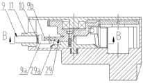
Fig. 1 is the structural representation of the utility model charging lock locking device lock pin when not stretching out.
Fig. 2 is the structural representation when lock pin stretches out in the charging lock locking device shown in Figure 1.
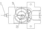
Fig. 3 is that A in the charging lock locking device shown in Figure 1 is to view.
Fig. 4 is that B in the charging lock locking device shown in Figure 2 is to view.
Fig. 5 is that C in the charging lock locking device shown in Figure 1 is to view.
Embodiment
Below in conjunction with drawings and Examples the utility model is described further.
Horizontal lock locking device of the present utility model generally is fixed on the body of charging socket.Contrast Fig. 1, this lock uint mainly is comprised ofhousing 1,gear wheel 3a,pinion 3b,motor 2, driving-chain 3, lock collar 7,lock pin 9,lock pin spring 10,sensitive switch 13,microswitch cam 23 and lock pin cam 29.Special circumstances might occur when considering charging, for example have a power failure or mechanical disorder, can't realize electronic release, design an armstrong's patent release mechanism on the basis of above-mentioned lock uint.The Horizontal lock locking device that the below's concrete analysis present embodiment provides.
Referring to Fig. 1, Fig. 3, gear wheel in the Horizontallock locking device 6 is made of one with lock collar 7 andlock pin cam 29, andgear wheel 3a andlock pin cam 2 be 9 upper and lower ends that place lock collar 7 respectively, rotor in the formation; Microswitchcam 23 is made of one with largehelical gear 6, andmicroswitch cam 23 places largehelical gear 6 upper ends, forms lower rotor.Rotate up and down body and connect byscrew 8 coaxial lines, form rotor.This rotor upper end is by bearing 4, and the lower end is rotatably connected on thehousing 1 by bearing 21.In described rotor oneside motor 2 is set, thismotor 2 is a direct current motor, andpinion 3b is connected on this dc motor shaft, thispinion 3b andgear wheel 3a engagement.Be provided with twosensitive switches 13 corresponding to thesemicroswitch cam 23 1 sides, thissensitive switch 13 mainly is comprised of sensitive switch body 13d,elastic spring 13a,feeler lever 13c andcontact 13b, the end ofcontact 13b andreed 13a is connected on the sensitive switch body 13d,feeler lever 13c is connected to thereed 13a other end, just in time facing to contact 13b, when the corresponding cam surface of the maximum rotating radius ofmicroswitch cam 23touches feeler lever 13c, just its pressure is contacted on the 13b of contact, makesensitive switch 13 closures; When the corresponding cam surface disengagement of the maximum rotating radius ofmicroswitch cam 23 is touched the pressure offeeler lever 13c, keep at a certain distance away onfeeler lever 13c and thedisengagement contact 13b,sensitive switch 13 is opened.Two sensitive switch 13(are referring to Fig. 3, Fig. 4) just be used on control motor rotating.Lock pin cam 29 is that cam surface is arranged on the cam on the circumferential direction take the lock collar axis as center of rotation, andlock pin 9 is conflicted on described cam surface in its axis mode vertical with the lock collar axis.Be provided with corresponding lockpin hole at thehousing 1 corresponding tolock pin cam 29, being connected with lockpin hole an ofaxle sleeve 11 coaxiallines.Lock pin 9 one ends are provided withrolling wheel support 9a, are rotationally connected aroller 9b on this rolling wheel support, and an end oflock pin 9 is conflicted on the lock pin cam with radial direction substantially byroller 9b, and the other end oflock pin 9 is socketed in the described axle sleeve 11.Equally,lock pin spring 10 is socketed on thelock pin 9, and this spring one end is conflicted on described rolling wheel support, and an end is conflicted on the corresponding end face ofaxle sleeve 11 or on the corresponding medial surface in the housing 1.Equally,axle sleeve 11 plays a part to the guiding oflock pin 9 with to lockpin spring 10 location.
Described rotor opposite side inhousing 1 arrangesbevel pinion 14 corresponding to the position of large helical gear, and this bevel pinion is bearing in the corresponding aperture ofhousing 1, and the axis in this hole and housing corresponding side surface are a α angle, see also Fig. 5.The mechanical release mechanism thatbevel pinion 14, largehelical gear 6, drivingcore body 15 andunlocking tool 17 consist of in the present embodiments.Be connected by screw betweenpinion 3b and the drivingcore body 15, be provided with spring 18 between the two in order to prevent screw loosening.Drive being connected on thebevel pinion 14 ofcore body 15 coaxial lines.Drive core body 15 and be provided withhole slot 15a, the corresponding end of thisunlocking tool 17 is provided with theboss 17a suitable with this hole slot, certainly also hole slot and boss can be arranged conversely, is separately positioned on unlockingtool 17 and the driving core body 15.The mating surface ofhole slot 15a andboss 17a is discontinuous smooth arc surface, like this when theboss 17a of the corresponding end of unlockingtool 17 inserts thehole slot 15a that drives on the core body, unlockingtool 17 can drive and drive the synchronously rotation ofcore body 15 dos, rotate by largehelical gear 6 and the engagement drive lock collar 7 ofbevel pinion 14,lock pin cam 29 and lock collar 7 coaxial rotation reach the purpose of release.
Above-mentioned Horizontal lock locking device is connected with the charging socket body by main body holder 12, provides the control power supply by electric vehicle system.Before charging, electric vehicle system sends the locking instruction, andmotor 2 drives described rotor by gear transmission chain and is rotated in the forward an about circle,lock pin cam 29 rotates thereupon, the radius of its cam increases gradually, andcam surface 29a promoteslock pin 9 and extend out in the charging plug, makes charging socket and plug-locking.Meanwhile, along with the rotation of lock collar 7,microswitch cam 23 is also rotated thereupon, when lock collar 7 is rotated a circle, the maximum rotating radius place ofmicroswitch cam 23 just in time touches thereed 13a pressure of a sidesensitive switch 13 on the 13b of contact, makessensitive switch 13 closures.This kind state description lock collar 7 is rotated in the forward and puts in place, i.e. locking puts in place, and the signal of telecommunication ofsensitive switch 13 closures feeds back to system.If it is not in place that lockpin 9 stretches out, because microswitchcam 23 is rotated withlock pin cam 29 coaxial lines, then lockpin cam 29 also will rotate not in place, it can not be pressed to reed 13a on the 13b of contact, the feedback signal of telecommunication can not be provided, and power supply can not be connected, and has guaranteed the safety of electricity consumption.When charging was finished,motor 2 was by the about circle ofgear transmission chain 3 lock collars 7 reverse rotations, and itshelicoid 29a no longer promotes latch-locking 9, andlocking plug spring 10 pushes up backupper locking plug 9, makes charging socket and plug release, and release is finished.Meanwhile, microswitchcam 23 makes the signal of telecommunication of opposite sidesensitive switch 13 closures can feed back to system, makes the object of controlling make corresponding action.
Claims (4)
1. the Horizontal lock locking device of an electrical automobile charging plug socket is characterized in that comprising housing, motor, gear wheel, pinion, lock collar, lock pin, lock pin spring, sensitive switch, microswitch cam and lock pin cam; Being connected on the lock collar of described gear wheel, microswitch cam and lock pin cam coaxial line, form rotor, this rotor is rotationally connected with in the described housing, and described motor places described rotor one side in the housing, pinion is connected on the machine shaft, pinion and gear wheel engagement; The cam surface of described microswitch cam is arranged on all side directions take the lock collar axis as center of rotation, and sensitive switch places a radially side of this microswitch cam, the cam surface conflict sensitive switch of microswitch cam; The cam surface of described lock pin cam is on the circumferential direction that is arranged on take the lock collar axis as center of rotation, and described lock pin is conflicted on described cam surface with its axis direction vertical with the lock collar axis.
2. the Horizontal lock locking device of described a kind of electrical automobile charging plug socket according to claim 1, it is characterized in that described charging lock locking device also is provided with mechanical release mechanism, this mechanical release mechanism comprises large helical gear, bevel pinion, drive core body and unlocking tool, be connected on the described lock collar described large helical gear coaxial line, described bevel pinion is rotationally connected with on the described housing and with large helical gear in the perpendicular mode of its axis and large helical gear axis and meshes, being connected on the bevel pinion of described driving core body coaxial line, described unlocking tool and this driving core body carry out in relative rotation socket connection of nothing by suitable hole slot and boss.
3. the Horizontal lock locking device of a kind of electrical automobile charging plug socket according to claim 2, it is characterized in that described gear wheel and large helical gear are separately positioned on the upper and lower of described lock collar, described lock pin cam places between gear wheel and the large helical gear, be provided with lockpin hole corresponding to the described housing of this lock pin cam, what one axle sleeve was concentric is connected with this lockpin hole, described lock pin one end is provided with rolling wheel support, be rotationally connected a roller on this rolling wheel support, lock pin one end passes through described roller conflicting on the lock pin cam, one end is socketed in the described axle sleeve, described lock pin spring is socketed on the lock pin, this spring one end is conflicted on described rolling wheel support, on the corresponding medial surface of end conflict on the corresponding end face of axle sleeve or in the housing.
4. the Horizontal lock locking device of a kind of electrical automobile charging plug socket according to claim 2, it is characterized in that described sensitive switch comprises body, elastic spring and contact at least, elastic spring one end and contact are connected on the described body, the elastic spring other end is relative with the contact, and keeps at a certain distance away.
Priority Applications (1)
| Application Number | Priority Date | Filing Date | Title |
|---|---|---|---|
| CN 201220272790CN202695855U (en) | 2012-06-11 | 2012-06-11 | Level locking device for charging plug and socket of electric automobile |
Applications Claiming Priority (1)
| Application Number | Priority Date | Filing Date | Title |
|---|---|---|---|
| CN 201220272790CN202695855U (en) | 2012-06-11 | 2012-06-11 | Level locking device for charging plug and socket of electric automobile |
Publications (1)
| Publication Number | Publication Date |
|---|---|
| CN202695855Utrue CN202695855U (en) | 2013-01-23 |
Family
ID=47551418
Family Applications (1)
| Application Number | Title | Priority Date | Filing Date |
|---|---|---|---|
| CN 201220272790Expired - Fee RelatedCN202695855U (en) | 2012-06-11 | 2012-06-11 | Level locking device for charging plug and socket of electric automobile |
Country Status (1)
| Country | Link |
|---|---|
| CN (1) | CN202695855U (en) |
Cited By (22)
| Publication number | Priority date | Publication date | Assignee | Title |
|---|---|---|---|---|
| CN104901082A (en)* | 2015-06-13 | 2015-09-09 | 石雨帆 | Plug board with function of automatic locking and shrinkage vertical-type plug board set therewith |
| CN105140710A (en)* | 2015-07-13 | 2015-12-09 | 桐乡市濮院舍尔得针织制衣厂 | Power supply device provided with guide rod and stable in power supplying |
| CN106463976A (en)* | 2015-02-12 | 2017-02-22 | 深圳来电科技有限公司 | Absorption charging device |
| CN107232922A (en)* | 2017-08-08 | 2017-10-10 | 陆馨琦 | A kind of cup |
| CN107342569A (en)* | 2017-07-21 | 2017-11-10 | 程明琴 | A kind of novel deduster device |
| CN108718024A (en)* | 2018-05-04 | 2018-10-30 | 费先艳 | A kind of automatic butt homing position type new-energy automobile charging equipment |
| CN108767590A (en)* | 2018-04-09 | 2018-11-06 | 东莞市天合机电开发有限公司 | A kind of three phase mains connector |
| DE102017123210A1 (en) | 2017-10-06 | 2019-04-11 | Kiekert Ag | Electromotive drive for automotive applications |
| DE102017123209A1 (en) | 2017-10-06 | 2019-04-11 | Kiekert Ag | Locking device of an electrical connection device for electric or hybrid motor vehicles |
| WO2019068287A1 (en) | 2017-10-06 | 2019-04-11 | Kiekert Ag | LOCKING DEVICE FOR AN ELECTRICAL CONNECTION DEVICE FOR ELECTRIC OR HYBRID MOTOR VEHICLES |
| DE102017130658A1 (en) | 2017-12-20 | 2019-06-27 | Kiekert Ag | Locking device for an electric charging device |
| DE102018114205A1 (en) | 2018-06-14 | 2019-12-19 | Kiekert Ag | LOCKING DEVICE FOR AN ELECTRIC CHARGING DEVICE OF A MOTOR VEHICLE |
| CN110994483A (en)* | 2020-01-03 | 2020-04-10 | 宁波绵长电子科技有限公司 | Cable head quick connection fixing equipment |
| DE102019117467A1 (en)* | 2019-06-28 | 2020-12-31 | Kiekert Aktiengesellschaft | Locking device for an electric charging device of a motor vehicle |
| CN112243553A (en)* | 2018-06-07 | 2021-01-19 | 泰连公司 | Charging assembly with override member on locking device |
| DE102019120962A1 (en)* | 2019-08-02 | 2021-02-04 | Kiekert Aktiengesellschaft | Electromotive drive unit for automotive applications |
| WO2021023329A1 (en) | 2019-08-07 | 2021-02-11 | Kiekert Ag | Electric charging device for a motor vehicle |
| WO2021032235A1 (en)* | 2019-08-21 | 2021-02-25 | Kiekert Ag | Electric charging device for a motor vehicle |
| DE102019127722A1 (en)* | 2019-10-15 | 2021-04-15 | Kiekert Aktiengesellschaft | LOCKING DEVICE FOR AN ELECTRONIC CHARGING DEVICE OF A MOTOR VEHICLE |
| US11325487B2 (en) | 2017-10-06 | 2022-05-10 | Kiekert Ag | Electric connection device for electric or hybrid motor vehicles |
| DE102020132025A1 (en) | 2020-12-02 | 2022-06-02 | Kiekert Aktiengesellschaft | Electromotive drive unit for motor vehicle applications |
| DE102020132027A1 (en) | 2020-12-02 | 2022-06-02 | Kiekert Aktiengesellschaft | Electromotive drive unit for motor vehicle applications |
- 2012
- 2012-06-11CNCN 201220272790patent/CN202695855U/ennot_activeExpired - Fee Related
Cited By (32)
| Publication number | Priority date | Publication date | Assignee | Title |
|---|---|---|---|---|
| CN106463976A (en)* | 2015-02-12 | 2017-02-22 | 深圳来电科技有限公司 | Absorption charging device |
| CN106463976B (en)* | 2015-02-12 | 2018-07-03 | 深圳来电科技有限公司 | Absorption charging device |
| CN104901082B (en)* | 2015-06-13 | 2017-07-28 | 石雨帆 | A kind of plate with automatic fastening function and the vertical plate group of the contraction with it |
| CN104901082A (en)* | 2015-06-13 | 2015-09-09 | 石雨帆 | Plug board with function of automatic locking and shrinkage vertical-type plug board set therewith |
| CN105140710A (en)* | 2015-07-13 | 2015-12-09 | 桐乡市濮院舍尔得针织制衣厂 | Power supply device provided with guide rod and stable in power supplying |
| CN107342569A (en)* | 2017-07-21 | 2017-11-10 | 程明琴 | A kind of novel deduster device |
| CN107232922A (en)* | 2017-08-08 | 2017-10-10 | 陆馨琦 | A kind of cup |
| US11325487B2 (en) | 2017-10-06 | 2022-05-10 | Kiekert Ag | Electric connection device for electric or hybrid motor vehicles |
| DE102017123210A1 (en) | 2017-10-06 | 2019-04-11 | Kiekert Ag | Electromotive drive for automotive applications |
| DE102017123209A1 (en) | 2017-10-06 | 2019-04-11 | Kiekert Ag | Locking device of an electrical connection device for electric or hybrid motor vehicles |
| WO2019068282A1 (en) | 2017-10-06 | 2019-04-11 | Kiekert Ag | ELECTROMOTORIC DRIVE FOR MOTOR VEHICLE APPLICATIONS |
| WO2019068287A1 (en) | 2017-10-06 | 2019-04-11 | Kiekert Ag | LOCKING DEVICE FOR AN ELECTRICAL CONNECTION DEVICE FOR ELECTRIC OR HYBRID MOTOR VEHICLES |
| US11566691B2 (en) | 2017-10-06 | 2023-01-31 | Kiekert Ag | Electromotive drive for motor vehicle applications |
| US11594841B2 (en) | 2017-12-20 | 2023-02-28 | Kiekert Ag | Locking device for an electrical charging device |
| DE102017130658A1 (en) | 2017-12-20 | 2019-06-27 | Kiekert Ag | Locking device for an electric charging device |
| CN108767590A (en)* | 2018-04-09 | 2018-11-06 | 东莞市天合机电开发有限公司 | A kind of three phase mains connector |
| CN108718024A (en)* | 2018-05-04 | 2018-10-30 | 费先艳 | A kind of automatic butt homing position type new-energy automobile charging equipment |
| CN108718024B (en)* | 2018-05-04 | 2019-08-13 | 孟永江 | A kind of automatic butt homing position type new-energy automobile charging equipment |
| CN112243553A (en)* | 2018-06-07 | 2021-01-19 | 泰连公司 | Charging assembly with override member on locking device |
| CN112243553B (en)* | 2018-06-07 | 2022-11-29 | 泰连公司 | Charging assembly with override member on locking device |
| DE102018114205A1 (en) | 2018-06-14 | 2019-12-19 | Kiekert Ag | LOCKING DEVICE FOR AN ELECTRIC CHARGING DEVICE OF A MOTOR VEHICLE |
| WO2019238167A1 (en) | 2018-06-14 | 2019-12-19 | Kiekert Ag | Locking device for an electrical charging device of a motor vehicle |
| DE102019117467A1 (en)* | 2019-06-28 | 2020-12-31 | Kiekert Aktiengesellschaft | Locking device for an electric charging device of a motor vehicle |
| DE102019120962A1 (en)* | 2019-08-02 | 2021-02-04 | Kiekert Aktiengesellschaft | Electromotive drive unit for automotive applications |
| WO2021023329A1 (en) | 2019-08-07 | 2021-02-11 | Kiekert Ag | Electric charging device for a motor vehicle |
| WO2021032235A1 (en)* | 2019-08-21 | 2021-02-25 | Kiekert Ag | Electric charging device for a motor vehicle |
| DE102019127722A1 (en)* | 2019-10-15 | 2021-04-15 | Kiekert Aktiengesellschaft | LOCKING DEVICE FOR AN ELECTRONIC CHARGING DEVICE OF A MOTOR VEHICLE |
| CN110994483A (en)* | 2020-01-03 | 2020-04-10 | 宁波绵长电子科技有限公司 | Cable head quick connection fixing equipment |
| DE102020132025A1 (en) | 2020-12-02 | 2022-06-02 | Kiekert Aktiengesellschaft | Electromotive drive unit for motor vehicle applications |
| DE102020132027A1 (en) | 2020-12-02 | 2022-06-02 | Kiekert Aktiengesellschaft | Electromotive drive unit for motor vehicle applications |
| WO2022117154A1 (en) | 2020-12-02 | 2022-06-09 | Kiekert Ag | Electromotive drive unit for motor vehicle applications |
| WO2022117151A1 (en) | 2020-12-02 | 2022-06-09 | Kiekert Ag | Electromotive drive unit for motor vehicle applications |
Similar Documents
| Publication | Publication Date | Title |
|---|---|---|
| CN202695855U (en) | Level locking device for charging plug and socket of electric automobile | |
| CN202759099U (en) | Locking device of electric automobile charging plug and socket | |
| CN102709754B (en) | Locking device for charging plug and charging socket of electric vehicle | |
| CN202759102U (en) | Vertical locking device of electric automobile charging plug and socket | |
| CN103872518B (en) | Lock device | |
| CN102686442B (en) | vehicle | |
| CN205894772U (en) | Stereo garage electric automobile interface that charges | |
| CN107336634B (en) | A kind of new-energy automobile charging unit | |
| US20150295355A1 (en) | Locking device for locking electrical plugs | |
| CN101702425B (en) | Battery installation structure for electric vehicles | |
| CN106964928B (en) | A kind of safe installation for welding | |
| CN107342523A (en) | A kind of modified new-energy automobile charging device | |
| CN102315559A (en) | Prevent the system that is disengaged between the charge port on plug and the motor vehicle | |
| JP2018507679A (en) | Modular vehicle system with improved operational reliability | |
| CN204651592U (en) | A kind of horizontal electronic lock | |
| CN201741933U (en) | Locking mechanism for charging connector electromagnetic lock | |
| CN201956509U (en) | Safe electricity-stealing prevention socket | |
| JP2020097816A (en) | Vehicle control device | |
| CN107336616A (en) | A kind of new new-energy automobile charging device | |
| CN107845915A (en) | It is a kind of to be connected stable new-energy automobile charging device | |
| CN205330294U (en) | Wireless unblanking or anti - lockwork | |
| CN203361798U (en) | A remote control electric bicycle motor lock | |
| CN205706221U (en) | Contractile automatic charging mechanical arm and be loaded with the electric automobile of this mechanical arm | |
| CN106320847A (en) | Intelligent lock for vehicle | |
| CN217306917U (en) | Automatic rotating socket for vehicle |
Legal Events
| Date | Code | Title | Description |
|---|---|---|---|
| C14 | Grant of patent or utility model | ||
| GR01 | Patent grant | ||
| ASS | Succession or assignment of patent right | Owner name:NANJING KANGNI NEW ENERGY AUTOMOBILE PARTS CO., LT Free format text:FORMER OWNER: NANJING KANGNI TECHNOLOGY INDUSTRY CO., LTD. Effective date:20150526 | |
| C41 | Transfer of patent application or patent right or utility model | ||
| TR01 | Transfer of patent right | Effective date of registration:20150526 Address after:210038 Jiangsu Province, Nanjing City Economic and Technological Development Zone Hengda Road No. 19 Patentee after:Nanjing health Buddhist nun new-energy automobile parts Co., Ltd Address before:210038 Jiangsu Province, Nanjing City Economic and Technological Development Zone Hengda Road No. 19 Patentee before:Nanjing Kangni Technology Industry Co., Ltd. | |
| CF01 | Termination of patent right due to non-payment of annual fee | ||
| CF01 | Termination of patent right due to non-payment of annual fee | Granted publication date:20130123 Termination date:20170611 |