CN202691632U - Light-emitting diode light bulb and its base - Google Patents
Light-emitting diode light bulb and its baseDownload PDFInfo
- Publication number
- CN202691632U CN202691632UCN201220093340XUCN201220093340UCN202691632UCN 202691632 UCN202691632 UCN 202691632UCN 201220093340X UCN201220093340X UCN 201220093340XUCN 201220093340 UCN201220093340 UCN 201220093340UCN 202691632 UCN202691632 UCN 202691632U
- Authority
- CN
- China
- Prior art keywords
- base
- light
- emitting diode
- light bulb
- led
- Prior art date
- Legal status (The legal status is an assumption and is not a legal conclusion. Google has not performed a legal analysis and makes no representation as to the accuracy of the status listed.)
- Expired - Fee Related
Links
- 229910052751metalInorganic materials0.000claimsdescription13
- 239000002184metalSubstances0.000claimsdescription13
- 230000017525heat dissipationEffects0.000description14
- WFKWXMTUELFFGS-UHFFFAOYSA-NtungstenChemical compound[W]WFKWXMTUELFFGS-UHFFFAOYSA-N0.000description13
- 229910052721tungstenInorganic materials0.000description12
- 239000010937tungstenSubstances0.000description12
- 238000010586diagramMethods0.000description8
- 238000013461designMethods0.000description6
- 238000000034methodMethods0.000description6
- 239000000758substrateSubstances0.000description5
- 230000008901benefitEffects0.000description4
- 230000000694effectsEffects0.000description4
- 238000004519manufacturing processMethods0.000description4
- 239000007769metal materialSubstances0.000description4
- 229910052782aluminiumInorganic materials0.000description3
- XAGFODPZIPBFFR-UHFFFAOYSA-NaluminiumChemical compound[Al]XAGFODPZIPBFFR-UHFFFAOYSA-N0.000description3
- 239000000463materialSubstances0.000description3
- 239000000047productSubstances0.000description3
- 239000007787solidSubstances0.000description3
- QSHDDOUJBYECFT-UHFFFAOYSA-NmercuryChemical compound[Hg]QSHDDOUJBYECFT-UHFFFAOYSA-N0.000description2
- 229910052753mercuryInorganic materials0.000description2
- 238000012986modificationMethods0.000description2
- 230000004048modificationEffects0.000description2
- 241000239226ScorpionesSpecies0.000description1
- 239000006227byproductSubstances0.000description1
- 239000000919ceramicSubstances0.000description1
- 238000013440design planningMethods0.000description1
- 230000005611electricityEffects0.000description1
- 230000002349favourable effectEffects0.000description1
- 239000011521glassSubstances0.000description1
- 239000003350keroseneSubstances0.000description1
- 230000007246mechanismEffects0.000description1
- 230000008569processEffects0.000description1
- 238000012827research and developmentMethods0.000description1
- 229910000679solderInorganic materials0.000description1
- 231100000167toxic agentToxicity0.000description1
- 239000003440toxic substanceSubstances0.000description1
- 239000002699waste materialSubstances0.000description1
Images


Landscapes
- Non-Portable Lighting Devices Or Systems Thereof (AREA)
- Arrangement Of Elements, Cooling, Sealing, Or The Like Of Lighting Devices (AREA)
Abstract
Translated fromChinese
Description
Translated fromChinese技术领域technical field
本实用新型是有关于一种发光二极管电灯泡,特别是有关于一种以热对流方式移除发光二极管电灯泡光源产生的热的设计。 The utility model relates to a light-emitting diode light bulb, in particular to a design for removing the heat generated by the light source of the light-emitting diode light bulb by means of heat convection. the
背景技术Background technique
传统的灯泡(light bulb),或是所谓的球泡灯,从爱迪生发明使用钨丝作为发光源开始,到目前已经超过百年。由于钨丝的发光是全方位的(omnidirection),并未对某一方向会输出较多的光源,因此迅速取代了以蜡蝎或是煤油灯等的光源。目前,市场已经接受具有全方位的光形的灯源。然而,由于以钨丝作为发光源的灯泡,消耗功率较大,也就是每瓦消耗的功率所能提供的照度在目前的光源当中算是相当的差。因此,许多的研发资源投注于提供更省电的光源来取代传统的钨丝灯泡。 The traditional light bulb (light bulb), or the so-called bulb lamp, has been more than a hundred years since Edison invented the use of tungsten wire as a light source. Since the tungsten filament emits light in all directions (omnidirection), it does not output more light sources in a certain direction, so it quickly replaced the light sources such as wax scorpions or kerosene lamps. Currently, the market has accepted light sources with omnidirectional light shapes. However, because the light bulb using tungsten filament as the light source consumes a lot of power, that is, the illuminance provided by the power consumed per watt is quite poor among the current light sources. Therefore, a lot of research and development resources are invested in providing more power-efficient light sources to replace traditional tungsten bulbs. the
目前市场接受度较高的是一种使用安定器的省电灯泡,又称为电子灯泡、紧凑型荧光灯,或是一体式荧光灯。这种省电灯泡的优点为节能的光效比传统的钨丝灯泡高得多。在同样照明条件下,前者所消耗的电能要少得多,所以被称为节能灯。但是与荧光灯(尤其是T5灯管)相比,还是比较浪费能源。再者,尺寸与传统的钨丝灯泡接近,并且使用与钨丝灯泡相同的接头以直接替换传统的钨丝灯泡。 At present, the most accepted in the market is a kind of energy-saving light bulb using a ballast, also known as electronic light bulb, compact fluorescent lamp, or integrated fluorescent lamp. The advantage of this energy-saving light bulb is that the energy-saving light efficiency is much higher than that of traditional tungsten filament light bulbs. Under the same lighting conditions, the former consumes much less electricity, so they are called energy-saving lamps. But compared with fluorescent lamps (especially T5 lamp tubes), it is still a waste of energy. Furthermore, the size is close to that of traditional tungsten light bulbs, and it uses the same connector as tungsten light bulbs to directly replace traditional tungsten light bulbs. the
然而,这种省电灯泡不是全然无缺点的。首先,有别于钨丝灯泡,省电灯泡在使用时,会产生些微的电磁波与微波。每一瓦的节能灯产生的电磁波强度约为4.67毫高斯,与微波约3.3μW/cm2。另外,由于安定器与荧光灯的特性,省电灯泡不但无法调光,不适用于可调光亮度的灯具,而且不适用需要经常开关的场所。另外,在省电灯泡的使用寿命终止的时候,省电灯泡所含的物料包括金属、玻璃和微量水银。尽管水银的含量完全符合国际安全限度,但属有毒物质,在运输及弃置时必须小心处理。 However, such energy-saving light bulbs are not entirely without disadvantages. First of all, different from tungsten filament bulbs, energy-saving bulbs will generate slight electromagnetic waves and microwaves when they are in use. The intensity of electromagnetic waves produced by energy-saving lamps per watt is about 4.67 milligauss, and that of microwaves is about 3.3 μW/cm2 . In addition, due to the characteristics of ballasts and fluorescent lamps, energy-saving bulbs cannot be dimmed, so they are not suitable for dimmable lamps, and they are not suitable for places that need to be switched on and off frequently. In addition, at the end of the life of the CFL, the CFL contains materials including metal, glass and trace amounts of mercury. Although the content of mercury is well within the international safety limit, it is a toxic substance and must be handled with care during transportation and disposal.
发光二极管照明是目前的照明装置中功耗最小的,最符合绿能的电子 照明产品。然而因为发光二极管的光源与发射出的光形,相较于传统的光源来说不但是点光源,而且具有指向性。虽然有着功耗极低的优点,但是要将点光源扩散并且可以适用成照明,还需要其他的设计与改良才可以达到。 Light-emitting diode lighting is the electronic lighting product that consumes the least power in current lighting devices and is most in line with green energy. However, because the light source and the emitted light shape of LEDs are not only point light sources, but also directional compared to traditional light sources. Although it has the advantage of extremely low power consumption, other designs and improvements are required to spread the point light source and apply it as lighting. the
目前,将发光二极管应用在灯泡上,已经有许多的产品在商业上贩卖。主流系列的产品,仍然是将发光二极管灯泡的外型作成与传统的钨丝灯泡接近,并且采用相同的接头。如图1所示是显示一种传统的发光二极管灯泡1的外观,主要包含一标准的E27接头10,一个在E27接头10上的底座30,以及一与底座30相接的灯罩70。光源主要会从灯罩70发射出来。在E27接头10里面,通常会安装发光二极管的电源。 At present, many products have been commercially sold by applying light-emitting diodes to light bulbs. The mainstream series of products still make the appearance of LED bulbs close to that of traditional tungsten filament bulbs, and use the same connectors. As shown in FIG. 1 , it shows the appearance of a traditional LED light bulb 1 , which mainly includes a
请同时参阅图2,将灯罩70移除后可以看到里面的发光二极管模块60位于底座30上,在图2中以三个发光二极管的封装体作为说明。一般实际上要安装几个发光二极管的封装体是由产品设计规划,与市场的需求所决定。由于发光二极管的光源指向性,以及在极小的体积内发光二极管会产生大量的热,当整个灯泡是强调高亮度的光源时,底座30本身往往会成为一个重要的散热装置。一般市面上的底座30,中心会有个小孔让电线通过,其中电线可以将发光二极管模块60与电源连接。为了增加散热的效果,底座30会采用易吸热的金属材料并且会设计许多的散热鳍片增加散热的表面绩。 Please also refer to FIG. 2 . After the lampshade 70 is removed, it can be seen that the
这种设计,不但会增加整个发光二极管灯泡的重量,并且因为底座30采用实心的结构,整个制造的成本会无法降低。在传统的钨丝灯泡,重量上相当的轻盈。所以,整个灯具在设计的时候就不需要考虑可以支撑较重的灯的灯泡。然而,改用发光二极管的灯泡后,由于底座的重量会造成灯具中与E27结合的母接头有可能无法支撑整个灯泡。因此,需要设计一个可以降低整体重量的发光二极管灯泡,并且可以达到良好的散热效果。 This design will not only increase the weight of the entire light emitting diode bulb, but also because the
实用新型内容Utility model content
本实用新型的目的在于提供一种发光二极管电灯泡及其底座,以期达到良好的散热效果。 The purpose of the utility model is to provide a light-emitting diode light bulb and its base, in order to achieve a good heat dissipation effect. the
为实现上述目的,本实用新型提供的发光二极管电灯泡,包含: In order to achieve the above object, the light-emitting diode light bulb provided by the utility model includes:
一螺牙接头; a threaded joint;
一底座,位于该螺牙接头上,为中空桶状结构; A base, located on the screw joint, is a hollow barrel-shaped structure;
一发光二极管模块,位于该底座上; A light-emitting diode module located on the base;
一电源,位于该螺牙接头内并与该螺牙接头电性连接,提供该发光二极管模块电源; A power supply, located in the threaded joint and electrically connected to the threaded joint, provides power to the LED module;
一底壳,位于该螺牙接头上,内含该底座; a bottom shell, located on the threaded joint, containing the base;
一灯罩,与该底壳相接。 A lampshade is connected with the bottom case. the
所述的发光二极管电灯泡,其中包含一圆盘固定该底座上,并且该发光二极管模块固定于该圆盘上。 The light emitting diode light bulb includes a disk fixed on the base, and the light emitting diode module is fixed on the disk. the
所述的发光二极管电灯泡,其中该底座上方具有复数个孔,该圆盘锁住于该底座上。 Said light-emitting diode light bulb, wherein there are a plurality of holes above the base, and the disk is locked on the base. the
所述的发光二极管电灯泡,其中该底座是利用热对流方式将该发光二极管模块所产生的热散出。 In the light-emitting diode light bulb, the base dissipates heat generated by the light-emitting diode module by heat convection. the
所述的发光二极管电灯泡,其中该螺牙接头为E27接头。 Said LED light bulb, wherein the threaded joint is an E27 joint. the
所述的发光二极管电灯泡,其中该底座与底壳的材质为金属。 Said LED light bulb, wherein the material of the base and the bottom case is metal. the
所述的发光二极管电灯泡,其中该底座与底壳为抽引式形成。 Said light emitting diode light bulb, wherein the base and the bottom shell are formed in a pull-out type. the
本实用新型还提供一种用于发光二极管电灯泡的底座,其中一端固接于一螺牙接头,另一端固接于一发光二极管模块,该底座本身为中空桶状结构,以热对流方式将该发光二极管模块产生的热以热对流方式散出。 The utility model also provides a base for light-emitting diode light bulbs, one end of which is fixedly connected to a screw joint, and the other end is fixedly connected to a light-emitting diode module. The heat generated by the LED modules is dissipated by heat convection. the
所述的底座,其中该底座上方具有复数个孔,固定该发光二极管模块。 The base has a plurality of holes above the base to fix the light emitting diode module. the
所述的底座,其中该底座为金属底座。 The base, wherein the base is a metal base. the
本实用新型的发光二极管电灯泡采用中空桶状的底座,不但可以使用热对流的方式提供发光二极管模块的散热,并且与传统的实心的底座相比较,拥有的重量较轻,可以让发光二极管电灯泡在重量的设计可以接近传统的钨丝灯泡。另外,减低的重量,同时也减低了金属材质的使用,可以降低制造的成本。 The light-emitting diode light bulb of the utility model adopts a hollow barrel-shaped base, which can not only provide heat dissipation for the light-emitting diode module by heat convection, but also has a lighter weight than the traditional solid base, allowing the light-emitting diode light bulb The weight of the design can be close to the traditional tungsten bulb. In addition, the reduced weight also reduces the use of metal materials, which can reduce the manufacturing cost. the
附图说明Description of drawings
图1为公知发光二极管电灯泡的外型示意图。 FIG. 1 is a schematic diagram of a known light-emitting diode light bulb. the
图2为公知发光二极管电灯泡的结构示意图。 Fig. 2 is a structural schematic diagram of a known LED light bulb. the
图3为本实用新型的发光二极管电灯泡的截面结构示意图,其中简介底座的散热方式。 Fig. 3 is a schematic cross-sectional structure diagram of the light-emitting diode light bulb of the present invention, in which the heat dissipation method of the base is briefly introduced. the
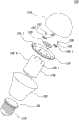
图4为本实用新型的发光二极管电灯泡分解示意图。 Fig. 4 is an exploded schematic view of the LED light bulb of the present invention. the
图5为本实用新型的发光二极管电灯泡的部分结构示意图。 Fig. 5 is a partial structural schematic diagram of the LED light bulb of the present invention. the
图6为本实用新型的发光二极管电灯泡模块的部分组装的结构示意图。 FIG. 6 is a schematic structural diagram of a partial assembly of the light emitting diode light bulb module of the present invention. the
图7为本实用新型的发光二极管电灯泡模块的组装完成的结构示意图。 FIG. 7 is a structural schematic diagram of the assembled LED light bulb module of the present invention. the
具体实施方式Detailed ways
本实用新型提出的发光二极管电灯泡,其包含一螺牙接头,一位于螺牙接头上的底座,一位于该底座上的发光二极管模块,一位于该螺牙接头内并与该螺牙接头电性连接的电源,一位于该螺牙接头上的底壳,以及与该底壳相接的一灯罩。上述的底壳内含该底座,而该底座为中空桶状结构。上述的电源是用以提供该发光二极管模块电源。 The light-emitting diode electric light bulb proposed by the utility model comprises a thread joint, a base located on the thread joint, a light-emitting diode module located on the base, and a light-emitting diode module located in the thread joint and electrically connected to the thread joint. A connected power supply, a bottom case on the threaded connector, and a lampshade attached to the bottom case. The base is included in the above-mentioned bottom case, and the base is a hollow barrel-shaped structure. The aforementioned power supply is used to provide power to the LED module. the
本实用新型的发光二极管电灯泡还包含一圆盘固定于该底座上,并且该发光二极管模块是固定于该圆盘上。上述的底座上方具有复数个孔,让该圆盘锁住该底座上。上述的底座是利用热对流方式将该发光二极管模块所产生的热散出。上述的底座与底壳的材质为金属,其形成方式为抽引式。上述的螺牙接头可为E27接头。 The light emitting diode light bulb of the utility model also includes a disc fixed on the base, and the light emitting diode module is fixed on the disc. There are a plurality of holes above the above-mentioned base, allowing the disc to be locked on the base. The above-mentioned base dissipates the heat generated by the LED module by heat convection. The above-mentioned base and bottom case are made of metal, and are formed in a pull-out type. The above-mentioned threaded joint can be an E27 joint. the
本实用新型同时提出一种用于发光二极管电灯泡的底座,一端固接于一螺牙接头,另一端固接于一发光二极管模块,该底座本身为中空桶状结构,以热对流方式将该发光二极管模块产生的热以热对流方式散出。 The utility model also proposes a base for light-emitting diode light bulbs, one end is fixed to a screw joint, and the other end is fixed to a light-emitting diode module. The heat generated by the diode modules is dissipated by convection. the
上述的底座上方具有复数个孔,用以固定该发光二极管模块。 A plurality of holes are provided above the base for fixing the LED module. the
本实用新型在此所探讨的方向为一种发光二极管电灯泡。为能彻底地了解本实用新型,将在下列的描述中提出详尽的步骤及其组成。显然地,本实用新型的施行并未限定于对发光二极管照明技术所熟悉的特殊细节。另一方面,众所周知的组成或步骤并未描述于细节中,以避免造成本实用新型不必要的限制。本实用新型的较佳实施例会详细描述如下,然而除了这些详细描述的外,本新型还可以广泛地施行在其他的实施例中,且本实 用新型的范围不受限定,以权利要求的范围为准。 The direction that the utility model discusses here is a kind of light-emitting diode light bulb. In order to thoroughly understand the utility model, detailed steps and components thereof will be proposed in the following description. Obviously, the implementation of the invention is not limited to specific details familiar from LED lighting technology. On the other hand, well-known components or steps have not been described in detail in order to avoid unnecessarily limiting the present invention. The preferred embodiments of the present utility model will be described in detail as follows, but except these detailed descriptions, the present model can also be widely implemented in other embodiments, and the scope of the present utility model is not limited, with the scope of the claims prevail. the
本实用新型提出一种使用中空桶状的底座,提供对流的散热方式,将发光二极管的热导出。中空桶状的底座,可以大幅降低整体的重量,并且因为减少使用金属材质可以降低成本。在本实用新型中,底座与底壳的材质皆可为金属铝,其制作方式皆可使用抽引式(Drawing Process)形成。在底座的表面上可以设计一些固接装置,例如一些孔洞,将一个圆盘与底座固定。圆盘,除了可以承载发光二极管模块的外,还可以提供灯罩的固接。一种简单的方式,是在圆盘上形成一些卡勾结构,用以将灯罩固定住。 The utility model proposes a hollow barrel-shaped base to provide a convective heat dissipation method to export the heat of the light-emitting diodes. The hollow barrel-shaped base can greatly reduce the overall weight, and reduce the cost by reducing the use of metal materials. In the present utility model, the material of the base and the bottom shell can be metal aluminum, and the manufacturing method can be formed by drawing process. Some fastening devices can be designed on the surface of the base, such as some holes, to fix a disk and the base. In addition to carrying the light-emitting diode module, the disk can also provide the fixing of the lampshade. A simple method is to form some hook structures on the disc to fix the lampshade. the
接下来,请参阅附图以说明本实用新型的较佳实施例。请参阅图3,在螺牙接头110上具有一底壳130,螺牙接头110主要是E26/E27接头。如果是小型的发光二极管电灯泡,可以使用像是小夜灯等E12接头。如果是应用在大型的照明灯具,可以使用E40接头。在底壳130的内部具有一底座140,其中底座140至少有两个功能;第一,用以支撑上面的发光二极管模块160,以及;第二,提供发光二极管模块160散热。在本实用新型一实施例中,底座140的材质主要是金属材质,形状为中空桶状。利用中空有利的条件,可以在底座140内提供热循环,如图3底座140内部的循环箭头所示。发光二极管模块160所产生的热,可以由这种热循环的方式,被带到螺牙接头110及/或底壳130上。底座140与底壳130的材质均为金属以增加散热,并且可为相同材质的金属,其形成方式可为抽引式。 Next, please refer to the accompanying drawings to illustrate the preferred embodiments of the present utility model. Please refer to FIG. 3 , there is a
在底座140上,与发光二极管模块160之间可具有一圆盘150,让发光二极管模块160安装于其上。在本实用新型的一实施例中,发光二极管模块160可为标准化的光引擎(light engine)。光引擎一般是在一小块的基板上将一个或是多个发光二极管封装体焊接在其上,其中基板可为印刷电路板、金属基印刷电路板(MCPCB;Metal core PCB)、陶瓷基板、或是铝基板等。通常会使用金属基印刷电路板或是铝基板,以增加散热的效果。光引擎的设计是来自于发光二极管封装体的体积过小,因为要将发光二极管封装体组件应用在一般的照明系统,需要尺寸大于一般发光二极管封装组件的机构,才能应用于照明设备上。目前,有ZHAGA联盟发展发光二极管光引擎接口的标准,包含光学度量接口(photometric interface),机构接口,热接口,以及电性接口的规范。 On the
在本实用新型的一实施例中,可以先将发光二极管模块160固定在圆盘150上,然后再将圆盘150固定在底座140上。圆盘150的尺寸可以跟底壳130一起密合即可,并且可以提供一较佳的反射面。 In an embodiment of the present invention, the
请参阅图4,显示本实用新型的发光二极管电灯泡100的各部件的爆炸图。在螺牙接头110上方具有一电源120用以提供发光二极管模块160电源。接着,一底壳130向下衔接螺牙接头110,内部具有底座140。在底座140上方具有数个孔,可以提供圆盘150与底座140之间的固定,例如使用螺丝固定。另外,可以在圆盘150的周围开孔,例如孔洞150-1与孔洞150-2,并且在底座140相对的位置的桶壁也开孔,例如孔洞140-1与孔洞140-2。孔洞140-1与孔洞140-2除了可以促进底座140内外的空气对流,也就是帮助散热之外,还可以让发光二极管模块160的线路通过孔洞140-1与孔洞140-2连接到电源120。在一实施例中,在圆盘150上的孔洞可以开两个或是两个以上。同样的,在底座140上也可以开两个或是两个以上的孔洞。在图4中仅以两个孔洞作为其中一实施例。发光二极管模块160固定在圆盘150上。灯罩170覆盖发光二集体模块160与圆盘150。此外,本实用新型的发光二极管电灯泡进一步具有一第一扣片165及一第二扣片166,其中,该第一扣片165及第二扣片166的两端分别具有一锁孔165-1及166-1,于组装时,可由两螺丝167及168分别穿过锁孔165-1及166-1将该发光二极管模块160锁定在圆盘150上,或者,也可以焊接方式将该发光二极管模块160固定于该圆盘150上。 Please refer to FIG. 4 , which shows an exploded view of various components of the LED
请参阅图5,是将发光二极管电灯泡的部分组件组合的结构示意图。将电源120安装在螺牙接头110上后,与底壳130组装,并且将底座140与螺牙接头110组装,其中底座140内具有电线,与电源120之间电性连接。 Please refer to FIG. 5 , which is a structural schematic diagram of the combination of some components of the LED light bulb. After the
请参阅图6,是在图5之后将发光二极管电灯泡的其他部分组件组合的结构示意图。本实用新型的发光二极管电灯泡于组装时,可藉由两螺丝167及168分别穿过锁孔165-1及166-1将该发光二极管模块160锁定在圆盘150上,或者,也可以焊接方式将该发光二极管模块160固定于该圆盘150上。然后,将圆盘150固定在底座140上,其中固定的方式可以是使用螺丝固定住。灯罩170从上方将发光二极管模块160与圆盘150遮盖, 结果如图7所示。在本实用新型的一实施例中,圆盘150上具有复数个卡勾结构152,用以固定该灯罩170。 Please refer to FIG. 6 , which is a schematic structural diagram of combining other components of the light-emitting diode light bulb after FIG. 5 . When assembling the light-emitting diode light bulb of the present utility model, the light-emitting
综上所述,本实用新型的特色及具体效益为中空桶状的底座不但可以使用热对流的方式提供发光二极管模块的散热,并且与传统的实心的底座相比较,拥有的重量较轻,可以让发光二极管电灯泡在重量的设计可以接近传统的钨丝灯泡。另外,减低的重量,同时也减低了金属材质的使用,可以降低制造的成本。 To sum up, the characteristics and specific benefits of this utility model are that the hollow barrel-shaped base can not only provide heat dissipation for the LED module by means of heat convection, but also has a lighter weight than the traditional solid base, and can The light-emitting diode light bulb is designed to be close to the traditional tungsten filament light bulb in terms of weight. In addition, the reduced weight also reduces the use of metal materials, which can reduce the manufacturing cost. the
显然地,依照上面实施例中的描述,本实用新型可能有许多的修正与差异。因此需要在其附加的权利要求范围内加以理解,除了上述详细的描述外,本实用新型还可以广泛地在其他的实施例中施行。上述仅为本实用新型的较佳实施例而已,并非用以限定本实用新型的申请专利范围;凡其它未脱离本实用新型所揭示的精神下所完成的等效改变或修饰,均应包含在申请的权利要求范围内。 Apparently, according to the descriptions in the above embodiments, the present utility model may have many modifications and differences. It is therefore to be understood within the scope of the appended claims that the invention may be practiced broadly in other embodiments than those detailed above. The above is only a preferred embodiment of the utility model, and is not intended to limit the patent scope of the utility model; all other equivalent changes or modifications that do not deviate from the spirit disclosed in the utility model should be included in the within the scope of the claims of the application. the
Claims (9)
Translated fromChinesePriority Applications (1)
| Application Number | Priority Date | Filing Date | Title |
|---|---|---|---|
| CN201220093340XUCN202691632U (en) | 2012-03-14 | 2012-03-14 | Light-emitting diode light bulb and its base |
Applications Claiming Priority (1)
| Application Number | Priority Date | Filing Date | Title |
|---|---|---|---|
| CN201220093340XUCN202691632U (en) | 2012-03-14 | 2012-03-14 | Light-emitting diode light bulb and its base |
Publications (1)
| Publication Number | Publication Date |
|---|---|
| CN202691632Utrue CN202691632U (en) | 2013-01-23 |
Family
ID=47547251
Family Applications (1)
| Application Number | Title | Priority Date | Filing Date |
|---|---|---|---|
| CN201220093340XUExpired - Fee RelatedCN202691632U (en) | 2012-03-14 | 2012-03-14 | Light-emitting diode light bulb and its base |
Country Status (1)
| Country | Link |
|---|---|
| CN (1) | CN202691632U (en) |
- 2012
- 2012-03-14CNCN201220093340XUpatent/CN202691632U/ennot_activeExpired - Fee Related
Similar Documents
| Publication | Publication Date | Title |
|---|---|---|
| US7976182B2 (en) | LED lamp assembly with temperature control and method of making the same | |
| US8536807B2 (en) | LED bulb | |
| KR101007913B1 (en) | Spiral radiator and bulb type LED lighting device using the same | |
| TW432000B (en) | Unitary sump frame and filling station island using the same | |
| CN201255391Y (en) | LED bulb | |
| US20130279164A1 (en) | Led lighting fixtures | |
| JP5472793B2 (en) | Lighting device and lighting fixture | |
| CN101871627A (en) | Preparation method of efficient heat dissipation LED lamp and lamp | |
| CN201273472Y (en) | Improved LED lamp structure | |
| CN201555054U (en) | A kind of LED light bulb | |
| US9217563B2 (en) | LED lighting assembly having electrically conductive heat sink for providing power directly to an LED light source | |
| JP2009043694A (en) | Light adjustment bulb led lamp for illumination | |
| KR20100006980A (en) | Lighting apparatus using led | |
| CN206429893U (en) | A kind of LED modules and illuminator | |
| CN201739908U (en) | LED projection lamp | |
| CN202691632U (en) | Light-emitting diode light bulb and its base | |
| KR101012308B1 (en) | Radiating device and bulb type LED lighting device using the same | |
| CN201318572Y (en) | Light emitting diode module and lamp using same | |
| KR101848488B1 (en) | FPL-type LED lamp | |
| CN203517403U (en) | Light source for illumination and an illumination device | |
| CN203131509U (en) | Light source for illuminating and lighting device | |
| CN203147365U (en) | Lighting light source and lighting device | |
| WO2013016953A1 (en) | Surface mount led lamp bulb | |
| CN205909112U (en) | Photo engine integral type down lamp | |
| CN202581222U (en) | Combined bulb radiating structure |
Legal Events
| Date | Code | Title | Description |
|---|---|---|---|
| C14 | Grant of patent or utility model | ||
| GR01 | Patent grant | ||
| CF01 | Termination of patent right due to non-payment of annual fee | Granted publication date:20130123 Termination date:20160314 | |
| CF01 | Termination of patent right due to non-payment of annual fee |