CN202677027U - Liquid crystal panel and display device thereof - Google Patents
Liquid crystal panel and display device thereofDownload PDFInfo
- Publication number
- CN202677027U CN202677027UCN 201220201861CN201220201861UCN202677027UCN 202677027 UCN202677027 UCN 202677027UCN 201220201861CN201220201861CN 201220201861CN 201220201861 UCN201220201861 UCN 201220201861UCN 202677027 UCN202677027 UCN 202677027U
- Authority
- CN
- China
- Prior art keywords
- liquid crystal
- crystal panel
- substrate
- polarizer
- phase retarder
- Prior art date
- Legal status (The legal status is an assumption and is not a legal conclusion. Google has not performed a legal analysis and makes no representation as to the accuracy of the status listed.)
- Expired - Lifetime
Links
Images


Landscapes
- Liquid Crystal (AREA)
Abstract
Translated fromChinese
Description
Translated fromChinese技术领域technical field
本实用新型属于液晶显示技术领域,具体涉及一种液晶面板以及包含该液晶面板的显示装置。The utility model belongs to the technical field of liquid crystal display, in particular to a liquid crystal panel and a display device including the liquid crystal panel.
背景技术Background technique
液晶显示器(Liquid Crystal Display,简称LCD)的主要构成部件是液晶面板,液晶面板主要包括彩膜基板和阵列基板,彩膜基板和阵列基板之间为液晶层,液晶层内填充有液晶,彩膜基板和阵列基板的各一侧还分别设置有一偏光片,即第一偏光片和第二偏光片。在阵列基板和/或彩膜基板之间设置有用于产生电场的电极,由于液晶本身为各向异性材料,通过电极的结构设置可以决定液晶的光学性质。当电极间不加电压(即电压为零)的时候,液晶分子平躺在与该液晶面板的板面平行的方向,此时液晶分子的长轴方向与该液晶面板的板面方向平行;当在电极上施加电压的时候,液晶分子逐渐开始“站立起来”,即液晶分子的长轴方向与液晶面板的板面方向开始倾斜,随着液晶层两端电压的增加,液晶分子开始旋转,当电压足够大的时候,液晶分子可以旋转到与该液晶面板的板面垂直的方向。即在加压情况下,液晶分子在电压的驱动下偏转不同的角度,可以使得设置在液晶面板后侧的背光源发出的光线透过液晶,并照射在屏幕上而形成图像。The main component of Liquid Crystal Display (LCD for short) is the liquid crystal panel. The liquid crystal panel mainly includes a color film substrate and an array substrate. There is a liquid crystal layer between the color film substrate and the array substrate. The liquid crystal layer is filled with liquid crystal. Each side of the substrate and the array substrate is further provided with a polarizer, that is, a first polarizer and a second polarizer. Electrodes for generating an electric field are arranged between the array substrate and/or the color filter substrate. Since the liquid crystal itself is an anisotropic material, the optical properties of the liquid crystal can be determined by the configuration of the electrodes. When no voltage is applied between the electrodes (that is, the voltage is zero), the liquid crystal molecules lie flat in the direction parallel to the panel surface of the liquid crystal panel, and the long axis direction of the liquid crystal molecules is parallel to the panel surface direction of the liquid crystal panel; when When a voltage is applied to the electrodes, the liquid crystal molecules gradually begin to "stand up", that is, the direction of the long axis of the liquid crystal molecules and the direction of the liquid crystal panel begin to incline. With the increase of the voltage across the liquid crystal layer, the liquid crystal molecules begin to rotate. When the voltage is large enough, the liquid crystal molecules can rotate to a direction perpendicular to the plane of the liquid crystal panel. That is, under the condition of pressure, the liquid crystal molecules deflect different angles under the drive of the voltage, which can make the light emitted by the backlight installed at the back of the liquid crystal panel pass through the liquid crystal and irradiate on the screen to form an image.
液晶显示器按显示机理可分为:动态散射模式(DS-LCD)、扭曲向列场效应模式(TN-LCD)、超扭曲向列模式(STN-LCD)、电控双折射模式(ECB-LCD)和宾主效应模式(HG-LCD)等多个类型。其中,如图1所示,在现有技术的ECB(Electrically ControlledBirefringence,简称ECB)模式液晶面板中,其包括彩膜基板、阵列基板、第一偏光片以及第二偏光片。所述彩膜基板包括第一基板2以及设置在第一基板2上的彩色膜层3和公共电极4,所述公共电极4设置在靠近液晶层的一侧;所述第一偏光片1设置在彩膜基板远离液晶层的一侧;所述阵列基板包括第二基板8以及设置在第二基板8上的TFT阵列7和数据电极6,所述数据电极6设置在靠近液晶层的一侧;所述第二偏光片9设置在阵列基板远离液晶层的一侧;第一偏光片1和第二偏光片9的透光轴(即透过轴)互相垂直正交设置。ECB模式液晶面板一般为常白模式,即在液晶显示器的工作过程中,在电极不加电压的情况下,液晶分子沿彩膜基板和阵列基板的板面平行排列,由于液晶的相位延迟量是二分之一波长,由第二偏光片入射的偏振光经过液晶层之后偏振方向旋转90°,从第一偏光片出射,形成亮态;在电极加电压的情况下,通过控制施加在公共电极4以及数据电极6之间的电压大小来形成垂直电场,使液晶层内的液晶发生偏转。液晶的最大偏转角度为90°,即液晶由横向旋转成为竖直状态,此时液晶的相位延迟量变为0°,由第二偏光片入射的偏振光直接经过液晶层而偏振态不发生变化,直接被第一偏光片吸收,形成暗态。对于ECB模式液晶面板而言,在未施加电压的状态下,具有液晶效率以及光线透过率均比较高的优点;在施加电压的状态下,由于液晶不能完全偏转,为了实现液晶的大角度偏转,势必要加大电极上施加的驱动电压,因此ECB模式液晶面板具有驱动电压较高、暗态漏光严重、色偏严重、对比度不高的缺点,同时,ECB模式液晶显示器还具有视角范围小,补偿较为复杂等不足。According to the display mechanism, liquid crystal displays can be divided into: dynamic scattering mode (DS-LCD), twisted nematic field effect mode (TN-LCD), super twisted nematic mode (STN-LCD), electronically controlled birefringence mode (ECB-LCD) ) and guest-host effect mode (HG-LCD) and other types. Wherein, as shown in FIG. 1 , in the conventional ECB (Electrically Controlled Birefringence, ECB for short) mode liquid crystal panel, it includes a color filter substrate, an array substrate, a first polarizer and a second polarizer. The color filter substrate includes a
随着技术的进步,出现了广视角技术,即边缘场开关技术(Fringe Field Switching,简称FFS)。在FFS模式液晶面板中,通过控制施加在同一像素间的数据电极以及公共电极之间的电压大小来形成边缘横向电场,使液晶在平行于基板的平面方向发生旋转偏移,从而得到图像。具体的,在未施加电压的状态下,液晶的取向为横向,因而这种液晶面板的视角较好,使得液晶显示器具有视角较宽的优点;在施加电压的状态下,由于电极正上方的电场垂直分量过大,造成液晶面板电场分布不均匀,导致电极正上方电场中的液晶的相位延迟量小于电极边缘处电场中的液晶的相位延迟量,因此,FFS模式液晶面板相对ECB模式液晶面板而言存在电极正上方处液晶效率以及光线透过率低,并且工艺复杂、成本较高的缺点。目前一般通过优化电极与液晶的夹角的方式来解决上述问题,但实践证明,优化电极与液晶的夹角可以在一定程度上提高透过率,但同时也使响应时间延长。With the advancement of technology, there has been a wide viewing angle technology, that is, Fringe Field Switching (FFS for short). In the FFS mode liquid crystal panel, the edge lateral electric field is formed by controlling the voltage applied between the data electrode and the common electrode between the same pixels, so that the liquid crystal is rotated and shifted in the direction parallel to the plane of the substrate, thereby obtaining an image. Specifically, in the state where no voltage is applied, the orientation of the liquid crystal is horizontal, so the viewing angle of this liquid crystal panel is better, so that the liquid crystal display has the advantage of a wider viewing angle; in the state of applying a voltage, due to the electric field directly above the electrode If the vertical component is too large, the electric field distribution of the liquid crystal panel is not uniform, and the phase delay of the liquid crystal in the electric field directly above the electrode is smaller than that of the liquid crystal in the electric field at the edge of the electrode. However, there are disadvantages of low liquid crystal efficiency and light transmittance directly above the electrodes, complicated process and high cost. At present, the above-mentioned problems are generally solved by optimizing the angle between the electrode and the liquid crystal, but practice has proved that optimizing the angle between the electrode and the liquid crystal can improve the transmittance to a certain extent, but at the same time, it also prolongs the response time.
实用新型内容Utility model content
本实用新型所要解决的技术问题是针对现有技术中ECB模式液晶面板存在的上述不足,提供一种液晶面板以及包含该液晶面板的显示装置,该液晶面板的视角范围广、且光线透过率高。The technical problem to be solved by the utility model is to provide a liquid crystal panel and a display device including the liquid crystal panel for the above-mentioned deficiencies existing in the ECB mode liquid crystal panel in the prior art. The viewing angle range of the liquid crystal panel is wide, and the light transmittance high.
解决本实用新型技术问题所采用的技术方案是该液晶面板包括彩膜基板、阵列基板、第一偏光片和第二偏光片,所述彩膜基板和阵列基板之间填充有液晶,所述第一偏光片设置在彩膜基板远离液晶的一侧,所述第二偏光片设置在阵列基板远离液晶的一侧,其中,该液晶面板中还包括具有光学补偿作用的相位延迟片。The technical solution adopted to solve the technical problem of the utility model is that the liquid crystal panel includes a color filter substrate, an array substrate, a first polarizer and a second polarizer, and liquid crystal is filled between the color filter substrate and the array substrate, and the first A polarizer is arranged on the side of the color filter substrate away from the liquid crystal, and the second polarizer is arranged on the side of the array substrate away from the liquid crystal, wherein the liquid crystal panel also includes a phase retarder with optical compensation.
其中,所述相位延迟片设置在彩膜基板一侧,所述彩膜基板包括第一基板以及设于所述第一基板上的公共电极和彩色膜层,所述相位延迟片处于第一基板和第一偏光片之间;或者,Wherein, the phase retarder is arranged on one side of the color filter substrate, and the color filter substrate includes a first substrate, a common electrode and a color film layer arranged on the first substrate, and the phase retarder is located on the first substrate and the first polarizer; or,
所述相位延迟片设置在阵列基板一侧,所述阵列基板包括第二基板以及设置在所述第二基板上的TFT阵列和数据电极,所述相位延迟片处于第二基板和第二偏光片之间;或者,The phase retarder is arranged on one side of the array substrate, and the array substrate includes a second substrate, a TFT array and a data electrode arranged on the second substrate, and the phase retarder is located between the second substrate and the second polarizer. between; or,
所述相位延迟片同时设置在彩膜基板的一侧和阵列基板的一侧,所述彩膜基板包括第一基板以及设于所述第一基板上的公共电极和彩色膜层,设置在彩膜基板一侧的相位延迟片处于第一基板和第一偏光片之间,所述阵列基板包括第二基板以及设置在所述第二基板上的TFT阵列和数据电极,设置在阵列基板一侧的相位延迟片处于第二基板和第二偏光片之间。The phase retarder is arranged on one side of the color filter substrate and one side of the array substrate at the same time, and the color filter substrate includes a first substrate, a common electrode and a color film layer arranged on the first substrate, and is arranged on the color filter The phase retarder on one side of the film substrate is between the first substrate and the first polarizer, and the array substrate includes a second substrate and a TFT array and a data electrode arranged on the second substrate, and is arranged on one side of the array substrate The phase retarder is between the second substrate and the second polarizer.
其中,所述第一偏光片的透过轴和第二偏光片的透过轴垂直设置,第一偏光片的透过轴和第二偏光片透光轴的方向与液晶排列方向成45°夹角。Wherein, the transmission axis of the first polarizer and the transmission axis of the second polarizer are vertically arranged, and the directions of the transmission axis of the first polarizer and the transmission axis of the second polarizer are at a 45° angle to the liquid crystal alignment direction. horn.
优选的是,所述相位延迟片的慢轴方向与液晶的慢轴方向垂直,由于所述第一偏光片的透过轴和第二偏光片的透过轴垂直设置,因此,第一偏光片和第二偏光片的透过轴与液晶或者与所述相位延迟片的慢轴之间的夹角为45°。Preferably, the direction of the slow axis of the phase retarder is perpendicular to the direction of the slow axis of the liquid crystal, and since the transmission axis of the first polarizer and the transmission axis of the second polarizer are vertically arranged, the first polarizer The included angle between the transmission axis of the second polarizer and the liquid crystal or the slow axis of the phase retarder is 45°.
进一步优选的是,所述第一相位延迟片或第二相位延迟片的相位延迟量等于或小于液晶的相位延迟量。Further preferably, the phase retardation of the first phase retarder or the second phase retarder is equal to or smaller than the phase retardation of the liquid crystal.
优选的是,所述相位延迟片采用A型相位延迟片或-A型相位延迟片。Preferably, the phase retarder is an A-type phase retarder or an -A-type phase retarder.
优选的是,所述相位延迟片采用环烯烃聚合物制成。Preferably, the phase retarder is made of cycloolefin polymer.
优选的是,所述相位延迟片的相位延迟量为二分之一波长。Preferably, the phase retardation of the phase retarder is half of the wavelength.
优选的是,所述相位延迟片的波长为380-780nm。进一步优选所述相位延迟片的波长为550nm。Preferably, the wavelength of the phase retarder is 380-780nm. Further preferably, the wavelength of the phase retarder is 550nm.
一种显示装置,包括液晶面板以及与所述液晶面板相连的驱动电路,其中,所述液晶面板采用上述的液晶面板。A display device, comprising a liquid crystal panel and a driving circuit connected to the liquid crystal panel, wherein the liquid crystal panel is the above-mentioned liquid crystal panel.
本实用新型的有益效果是:通过在液晶面板中增设相位延迟片,改变了液晶分子的光学透过方式,使得该液晶面板兼具FFS模式和ECB模式液晶面板的优点,即该液晶面板不但具有ECB模式液晶面板的液晶效率高、高透过率、工艺成本低等优点,还具有FFS模式液晶面板的视角范围广、色偏较小、驱动电压低等优点。The beneficial effects of the utility model are: by adding a phase retarder in the liquid crystal panel, the optical transmission mode of the liquid crystal molecules is changed, so that the liquid crystal panel has the advantages of both the FFS mode and the ECB mode liquid crystal panel, that is, the liquid crystal panel not only has The ECB mode liquid crystal panel has the advantages of high liquid crystal efficiency, high transmittance, and low process cost. It also has the advantages of a wide viewing angle range, small color shift, and low driving voltage of the FFS mode liquid crystal panel.
附图说明Description of drawings
图1为现有技术中ECB模式液晶面板的结构示意图;FIG. 1 is a schematic structural diagram of an ECB mode liquid crystal panel in the prior art;
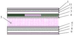
图2为本实用新型实施例1、2中液晶面板的结构示意图;Fig. 2 is the schematic structural diagram of the liquid crystal panel in the
图3为本实用新型实施例3、4中液晶面板的结构示意图;Fig. 3 is the schematic structural diagram of the liquid crystal panel in the
图4为本实用新型实施例5中液晶面板的结构示意图;Fig. 4 is a schematic structural diagram of a liquid crystal panel in
图5为本实用新型实施例1中液晶面板的视角特性图。FIG. 5 is a characteristic view of the viewing angle of the liquid crystal panel in
图中:1-第一偏光片;2-第一基板;3-彩色膜层;4-公共电极;5-液晶层;6-数据电极;7-TFT阵列;8-第二基板;9-第二偏光片;11-第一相位延迟片;12-第二相位延迟片。In the figure: 1-first polarizer; 2-first substrate; 3-color film layer; 4-common electrode; 5-liquid crystal layer; 6-data electrode; 7-TFT array; 8-second substrate; 9- The second polarizer; 11—the first phase retardation film; 12—the second phase retardation film.
具体实施方式Detailed ways
为使本领域技术人员更好地理解本实用新型的技术方案,下面结合附图和具体实施方式对本实用新型液晶面板以及包含该液晶面板的显示装置作进一步详细描述。In order to enable those skilled in the art to better understand the technical solutions of the present invention, the liquid crystal panel of the present invention and the display device including the liquid crystal panel will be further described in detail below with reference to the drawings and specific embodiments.
本实用新型的技术构思在于,根据现有技术中FFS模式液晶面板具有视角范围宽的优点,而同时相对ECB模式液晶面板又存在效率低以及光线透过率低的缺点,ECB模式液晶面板的液晶效率高,其光线透过率也比较高的优点,在ECB模式液晶面板的基础上进行改进,使该液晶面板兼具ECB模式液晶面板和FFS模式液晶面板的优点,从而得到一种视角范围广、光线透过率高、视角色偏较小、驱动电压低、且成本低的液晶面板。The technical idea of the present utility model is that, according to the advantages of wide viewing angle range in the FFS mode liquid crystal panel in the prior art, and the disadvantages of low efficiency and low light transmittance relative to the ECB mode liquid crystal panel, the liquid crystal of the ECB mode liquid crystal panel The advantages of high efficiency and relatively high light transmittance are improved on the basis of the ECB mode liquid crystal panel, so that the liquid crystal panel has the advantages of both the ECB mode liquid crystal panel and the FFS mode liquid crystal panel, thus obtaining a wide viewing angle range , high light transmittance, small viewing angle, low driving voltage, and low cost liquid crystal panel.
该液晶面板包括彩膜基板、阵列基板、第一偏光片和第二偏光片,所述彩膜基板和阵列基板之间填充有液晶,所述第一偏光片设置在彩膜基板远离液晶的一侧,所述第二偏光片设置在阵列基板远离液晶的一侧,该液晶面板中还包括具有光学补偿作用的相位延迟片。The liquid crystal panel includes a color filter substrate, an array substrate, a first polarizer and a second polarizer, liquid crystals are filled between the color filter substrate and the array substrate, and the first polarizer is arranged on a side of the color filter substrate far away from the liquid crystal. On the side, the second polarizer is arranged on the side of the array substrate away from the liquid crystal, and the liquid crystal panel also includes a phase retarder with an optical compensation function.
一种显示装置,包括液晶面板以及与所述液晶面板相连的驱动电路,其中,所述液晶面板采用上述的液晶面板。A display device, comprising a liquid crystal panel and a driving circuit connected to the liquid crystal panel, wherein the liquid crystal panel is the above-mentioned liquid crystal panel.
实施例1Example 1
如图2所示,本实施例中的液晶面板属于ECB模式液晶面板。该液晶面板包括彩膜基板、阵列基板、第一偏光片1以及第二偏光片9。彩膜基板和阵列基板之间为液晶层5,所述液晶层5由液晶形成。第一偏光片1设置在彩膜基板远离液晶层的一侧,第二偏光片9设置在阵列基板远离液晶层5的一侧。所述彩膜基板包括第一基板2、以及依次设置在第一基板2上的彩色膜层3和公共电极4,阵列基板包括第二基板8、以及依次设置在第二基板8上的TFT阵列7和数据电极6。该液晶面板中还包括具有光学补偿作用的相位延迟片。其中,相位延迟片(Retarder,又称波片),包括两个互相正交的偏振分量,光束通过该波片的两个互相正交的偏振分量产生相位偏移,从而能够调整光束的偏振状态。As shown in FIG. 2 , the liquid crystal panel in this embodiment belongs to the ECB mode liquid crystal panel. The liquid crystal panel includes a color filter substrate, an array substrate, a
本实施例中,所述相位延迟片为设置在第一基板2和第一偏光片1之间的第一相位延迟片11。具体的,由于相位延迟片一般为薄膜材料,因此,可以将相位延迟片贴附于第一偏光片1上。In this embodiment, the phase retarder is a
所述第一偏光片1的透过轴和第二偏光片9的透过轴垂直设置(即正交设置),所述第一相位延迟片11的慢轴方向(即相位延迟片中光线传播速度慢的方向)与液晶的慢轴方向垂直,所述第一相位延迟片11的慢轴方向与第一偏光片1的透过轴之间的夹角和第一相位延迟片11的慢轴方向与第二偏光片9的透过轴之间的夹角均为45°。The transmission axis of the
其中,第一相位延迟片11的相位延迟量等于或小于液晶的相位延迟量。如果第一相位延迟片11的相位延迟量等于液晶的相位延迟量,则在不加电压情况下,液晶面板为暗态;如果第一相位延迟片11的相位延迟量小于液晶的相位延迟量,则需要加一定电压才能使液晶面板达到暗态。这里,液晶面板在加电压状况下,液晶的相位延迟量随着电压的逐渐升高而逐渐减小,因此在某一时刻能够使得-A型相位延迟片的相位延迟量与液晶的相位延迟量刚好完全相等,相位延迟片的相位延迟量与液晶的相位延迟量完全相互抵消,光线不能透过,出现透过率最低的情况,形成暗态。本实施例中,优选第一相位延迟片11的相位延迟量等于液晶的相位延迟量。Wherein, the phase retardation of the
本实施例中,第一相位延迟片11采用-A型相位延迟片(-Aplate),在-A型相位延迟片中,x、y、z三向折射率的大小为Nx<Ny=Nz(xy方向即在形成相位延迟片的薄膜平面内,z方向指薄膜的法线方向),其宽度方向的折射率小于长度方向上的折射率。In this embodiment, the
其中,所述第一相位延迟片11采用环烯烃聚合物制成,对于某一特定材料而言,其每个方向(即x、y、z方向)上针对每个波长的折射率(N)是一定的,在材料不变的情况下,相位延迟量是由所选材料(即薄膜材料)的厚度(d)决定的,即相位延迟片的相位延迟量等于该薄膜平面内的折射率差与该薄膜的厚度之积(相位延迟量=ΔN*d=(Nx-Ny)*d,或者,相位延迟量=ΔN*d=[(Nx+Ny)/2-Nz]*d。其中,Nx代表平面内慢轴方向上的折射率,Ny代表在平面内与Nx成直角方向上的折射率,Nz代表在与Nx和Ny成直角方向上的折射率。Wherein, the
在本实施例中,第一相位延迟片11的相位延迟量为二分之一波长。由于可见光的波长范围为380-780nm,因此,在本实施例中相位延迟片的波长范围可相应选择为380-780nm,此时二分之一波长为190-390nm;当波长选择为550nm时,此时二分之一波长为275nm。在实际设计中,可根据液晶面板的实际应用环境相应地调整相位延迟片的波长,以达到需要的相位延迟量。In this embodiment, the phase retardation of the
在本实施例的液晶面板中,通过在数据电极6与公共电极4之间施加不同的电压,即可控制液晶分子的偏转,从而获得不同的液晶折射率,以及获得不同的液晶偏转量从而实现对光的相位延迟。In the liquid crystal panel of this embodiment, by applying different voltages between the
本实施例液晶面板为ECB模式液晶面板,该液晶面板具有常黑显示模式,其工作模式为,在电极不加电压的情况下,液晶的相位延迟量最大,此时液晶的相位延迟量和第一相位延迟片11的相位延迟量相互抵消,形成暗态。在形成暗态的常黑模式下,液晶因为没有偏转所以取向比较规则,因此漏光较少,所以液晶面板的视角较好;在电极加电压的情况下,随着电压的升高,液晶开始偏转,液晶的有效相位延迟量逐渐下降,同时透过率开始增加,形成亮态。The liquid crystal panel of this embodiment is an ECB mode liquid crystal panel, and the liquid crystal panel has a normally black display mode, and its working mode is that when no voltage is applied to the electrodes, the phase delay of the liquid crystal is the largest, and at this time the phase delay of the liquid crystal and the second The phase delays of one
如图5所示,其中阴影区域表示对比度10以上的区域,可见,本实施例中ECB模式的液晶面板具有很宽的视角范围,其视角范围可与FFS模式、IPS模式的视角范围相当。As shown in FIG. 5 , the shaded area represents the area with a contrast ratio of 10 or more. It can be seen that the LCD panel in ECB mode in this embodiment has a wide viewing angle range, which is comparable to that in FFS mode and IPS mode.
通过上面的分析可知,在本实施例中,通过在彩膜基板一侧设置第一相位延迟片不但可以提高液晶面板的液晶效率(液晶效率比FFS模式液晶面板高),而且能扩大视角范围(视角范围比ECB模式液晶面板广)。在现有技术中,FFS模式液晶面板的液晶效率一般为72%左右,而本实施例中液晶面板的液晶效率大于80%;在视角方面,本实施例中液晶面板的视角范围与现有技术中FFS模式液晶面板的视角相当,即其在水平方向(上、下、左、右四个方向)均能达到178°的视角。From the above analysis, it can be known that in this embodiment, by arranging the first phase retarder on the side of the color filter substrate, not only can the liquid crystal efficiency of the liquid crystal panel be improved (the liquid crystal efficiency is higher than that of the FFS mode liquid crystal panel), but also the viewing angle range can be expanded ( The viewing angle range is wider than that of the ECB mode LCD panel). In the prior art, the liquid crystal efficiency of the FFS mode liquid crystal panel is generally about 72%, while the liquid crystal efficiency of the liquid crystal panel in this embodiment is greater than 80%. In terms of viewing angle, the viewing angle range of the liquid crystal panel in this embodiment is different from that of the prior art. The viewing angle of the medium FFS mode LCD panel is equivalent, that is, it can reach a viewing angle of 178° in the horizontal direction (up, down, left, and right).
一种显示装置,包括液晶面板以及与所述液晶面板相连的驱动电路,其中所述液晶面板采用本实施例的液晶面板。A display device includes a liquid crystal panel and a driving circuit connected to the liquid crystal panel, wherein the liquid crystal panel adopts the liquid crystal panel of this embodiment.
实施例2Example 2
本实施例与实施例1的区别在于,第一相位延迟片11的类型不同。The difference between this embodiment and
本实施例中,第一相位延迟片11采用A型相位延迟片(Aplate)。在A型相位延迟片中,x、y、z三向折射率的大小为Nx>Ny=Nz,即其宽度方向的折射率大于长度方向上的折射率。In this embodiment, the
采用A型相位延迟片,与采用-A型相位延迟片比较而言,能够使得液晶面板的制作成本更低,液晶效率会得到很好的改善;但是视角范围会有一定程度的下降。The use of the A-type phase retarder, compared with the use of the -A-type phase retarder, can make the production cost of the liquid crystal panel lower, and the efficiency of the liquid crystal will be improved; but the viewing angle range will be reduced to a certain extent.
本实施例中液晶面板的其他结构和液晶面板的工作模式与实施例1相同,这里不再赘述。Other structures of the liquid crystal panel and working modes of the liquid crystal panel in this embodiment are the same as those in
一种显示装置,包括液晶面板以及与所述液晶面板相连的驱动电路,其中所述液晶面板采用本实施例的液晶面板。A display device includes a liquid crystal panel and a driving circuit connected to the liquid crystal panel, wherein the liquid crystal panel adopts the liquid crystal panel of this embodiment.
实施例3Example 3
如图3所示,本实施例与实施例1的区别在于,相位延迟片设置在阵列基板一侧。As shown in FIG. 3 , the difference between this embodiment and
本实施例中,所述相位延迟片为设置在第二基板8和第二偏光片9之间的第二相位延迟片12。In this embodiment, the phase retarder is a
所述第一偏光片1的透过轴和第二偏光片9的透过轴垂直设置(即正交设置),所述第二相位延迟片12的慢轴方向(即相位延迟片中光线传播速度慢的方向)与液晶的慢轴方向垂直,所述第二相位延迟片12的慢轴方向与第一偏光片1的透过轴之间的夹角和第二相位延迟片12的慢轴方向与第二偏光片9的透过轴之间的夹角均为45°。The transmission axis of the
本实施例中,第二相位延迟片12的相位延迟量等于液晶的相位延迟量。In this embodiment, the phase delay of the
第二相位延迟片12采用-A型相位延迟片(-A plate)。在-A型相位延迟片中,x、y、z三向折射率的大小为Nx<Ny=Nz,即其宽度方向的折射率小于长度方向上的折射率。The
本实施例中液晶面板的其他结构和液晶面板的工作模式与实施例1相同,这里不再赘述。Other structures of the liquid crystal panel and working modes of the liquid crystal panel in this embodiment are the same as those in
一种显示装置,包括液晶面板以及与所述液晶面板相连的驱动电路,其中所述液晶面板采用本实施例的液晶面板。A display device includes a liquid crystal panel and a driving circuit connected to the liquid crystal panel, wherein the liquid crystal panel adopts the liquid crystal panel of this embodiment.
实施例4Example 4
本实施例与实施例3的区别在于,第二相位延迟片12的类型不同。The difference between this embodiment and
所述第二相位延迟片采用A型相位延迟片(Aplate)。在该第二相位延迟片中,x、y、z三向折射率的大小为Nx>Ny=Nz,即其宽度方向的折射率大于长度方向上的折射率。The second phase retarder is an A-type phase retarder (Aplate). In the second phase retarder, the refractive index in the x, y, and z directions is Nx>Ny=Nz, that is, the refractive index in the width direction is greater than that in the length direction.
采用A型相位延迟片后的ECB模式液晶面板与采用FFS模式液晶面板比较而言,能够使得液晶面板的制作成本更低,液晶效率会得到很好的改善;但是视角范围会有一定程度的下降。Compared with the FFS mode LCD panel, the ECB mode LCD panel using the A-type phase retarder can make the production cost of the LCD panel lower, and the liquid crystal efficiency will be improved; but the viewing angle range will be reduced to a certain extent. .
本实施例中液晶面板的其他结构和液晶面板的工作模式与实施例3相同,这里不再赘述。Other structures of the liquid crystal panel and working modes of the liquid crystal panel in this embodiment are the same as those in
一种显示装置,包括液晶面板以及与所述液晶面板相连的驱动电路,其中所述液晶面板采用本实施例的液晶面板。A display device includes a liquid crystal panel and a driving circuit connected to the liquid crystal panel, wherein the liquid crystal panel adopts the liquid crystal panel of this embodiment.
实施例5Example 5
如图4所示,本实施例与实施例1的区别在于,相位延迟片包括两片,所述两片相位延迟片分别设置在彩膜基板和阵列基板各一侧。As shown in FIG. 4 , the difference between this embodiment and
本实施例中,设置在彩膜基板一侧的相位延迟片为第一相位延迟片11,设置在阵列基板一侧的相位延迟片为第二相位延迟片12。其中,第一相位延迟片11设置在彩膜基板与第一偏光片1之间,第二相位延迟片12设置在阵列基板与第二偏光片9之间。In this embodiment, the phase retarder disposed on the side of the color filter substrate is the
第一相位延迟片11和第二相位延迟片12的相位延迟量之和等于液晶的相位延迟量。这里,第一相位延迟片11和第二相位延迟片12既可以选择-A型相位延迟片,也可以选择A型相位延迟片,其角度设置与实施例1-4中的角度设置相同。The sum of the phase retardation of the
本实施例中液晶面板的其他结构和液晶面板的工作模式与实施例1相同,这里不再赘述。Other structures of the liquid crystal panel and working modes of the liquid crystal panel in this embodiment are the same as those in
一种显示装置,包括液晶面板以及与所述液晶面板相连的驱动电路,其中所述液晶面板采用本实施例的液晶面板。所述显示装置,可以为液晶电视、手机、笔记本电脑、平板电脑等任何具有显示功能的产品或部件。A display device includes a liquid crystal panel and a driving circuit connected to the liquid crystal panel, wherein the liquid crystal panel adopts the liquid crystal panel of this embodiment. The display device may be any product or component with a display function, such as a liquid crystal television, a mobile phone, a notebook computer, a tablet computer, and the like.
本实用新型实施例1-5中通过在液晶面板中增设相位延迟片提供光学补偿作用,提供了一种常黑模式的ECB模式液晶面板(传统的ECB模式液晶面板为常白模式),由于液晶面板的视角主要由暗态漏光决定,在本实施例中,暗态下的液晶处于水平状态,使得暗态漏光较少,因此通过液晶和相位延迟片的匹配保证了液晶面板获得较好的视角;同时,相位延迟片的设置相当于增加了液晶的相位延迟量(当二者的相位延迟量均大于二分之一波长时),通过调整液晶和相位延迟片的相位延迟量可以达到降低驱动电压的效果;同时,还具有改变光线透过率的作用,解决了现有的ECB模式液晶面板视角范围小的问题,相对FFS模式液晶面板而言还具有低成本、高透过率等优点。In Embodiments 1-5 of the present utility model, a phase retardation film is added to the liquid crystal panel to provide optical compensation, and a normally black mode ECB mode liquid crystal panel is provided (the traditional ECB mode liquid crystal panel is normally white mode), because the liquid crystal The viewing angle of the panel is mainly determined by the light leakage in the dark state. In this embodiment, the liquid crystal in the dark state is in a horizontal state, so that the light leakage in the dark state is less, so the matching of the liquid crystal and the phase retarder ensures that the liquid crystal panel can obtain a better viewing angle. ; At the same time, the setting of the phase retarder is equivalent to increasing the phase retardation of the liquid crystal (when the phase retardation of the two is greater than one-half of the wavelength), by adjusting the phase retardation of the liquid crystal and the phase retardation, it can be reduced. At the same time, it also has the effect of changing the light transmittance, which solves the problem of the small viewing angle range of the existing ECB mode liquid crystal panel, and has the advantages of low cost and high transmittance compared with the FFS mode liquid crystal panel.
综上所述,本实用新型通过在彩膜基板与第一偏光片之间和/或在阵列基板与第二偏光片之间增设相位延迟片,使得该液晶面板不但具有ECB模式液晶面板的高透过率、液晶效率高、成本低等优点,同时能达到与FFS模式液晶面板相同的视角范围以及驱动电压低的优点。In summary, the utility model adds a phase retarder between the color filter substrate and the first polarizer and/or between the array substrate and the second polarizer, so that the liquid crystal panel not only has the high Transmittance, high liquid crystal efficiency, low cost, etc., can achieve the same viewing angle range as the FFS mode liquid crystal panel and the advantages of low driving voltage.
可以理解的是,以上实施方式仅仅是为了说明本实用新型的原理而采用的示例性实施方式,然而本实用新型并不局限于此。对于本领域内的普通技术人员而言,在不脱离本实用新型的精神和实质的情况下,可以做出各种变型和改进,这些变型和改进也视为本实用新型的保护范围。It can be understood that, the above embodiments are only exemplary embodiments adopted to illustrate the principles of the present invention, but the present invention is not limited thereto. For those skilled in the art, various modifications and improvements can be made without departing from the spirit and essence of the present utility model, and these variations and improvements are also regarded as the protection scope of the present utility model.
Claims (10)
Priority Applications (1)
| Application Number | Priority Date | Filing Date | Title |
|---|---|---|---|
| CN 201220201861CN202677027U (en) | 2012-05-07 | 2012-05-07 | Liquid crystal panel and display device thereof |
Applications Claiming Priority (1)
| Application Number | Priority Date | Filing Date | Title |
|---|---|---|---|
| CN 201220201861CN202677027U (en) | 2012-05-07 | 2012-05-07 | Liquid crystal panel and display device thereof |
Publications (1)
| Publication Number | Publication Date |
|---|---|
| CN202677027Utrue CN202677027U (en) | 2013-01-16 |
Family
ID=47497923
Family Applications (1)
| Application Number | Title | Priority Date | Filing Date |
|---|---|---|---|
| CN 201220201861Expired - LifetimeCN202677027U (en) | 2012-05-07 | 2012-05-07 | Liquid crystal panel and display device thereof |
Country Status (1)
| Country | Link |
|---|---|
| CN (1) | CN202677027U (en) |
Cited By (3)
| Publication number | Priority date | Publication date | Assignee | Title |
|---|---|---|---|---|
| CN103698893A (en)* | 2013-03-29 | 2014-04-02 | 京东方科技集团股份有限公司 | Three-dimensional liquid crystal display device |
| CN109416482A (en)* | 2017-06-15 | 2019-03-01 | 京东方科技集团股份有限公司 | The method that fringing field drives liquid crystal display panel and determines the optical axis direction of glassy layer in fringing field driving liquid crystal display panel |
| CN112363347A (en)* | 2020-11-30 | 2021-02-12 | 厦门天马微电子有限公司 | Liquid crystal display panel and display device |
- 2012
- 2012-05-07CNCN 201220201861patent/CN202677027U/ennot_activeExpired - Lifetime
Cited By (6)
| Publication number | Priority date | Publication date | Assignee | Title |
|---|---|---|---|---|
| CN103698893A (en)* | 2013-03-29 | 2014-04-02 | 京东方科技集团股份有限公司 | Three-dimensional liquid crystal display device |
| CN103698893B (en)* | 2013-03-29 | 2016-02-24 | 京东方科技集团股份有限公司 | Three-dimensional liquid crystal display device |
| CN109416482A (en)* | 2017-06-15 | 2019-03-01 | 京东方科技集团股份有限公司 | The method that fringing field drives liquid crystal display panel and determines the optical axis direction of glassy layer in fringing field driving liquid crystal display panel |
| CN109416482B (en)* | 2017-06-15 | 2021-10-01 | 京东方科技集团股份有限公司 | Fringe field driven liquid crystal display panel and method for determining optical axis direction of glass layer in fringe field driven liquid crystal display panel |
| CN112363347A (en)* | 2020-11-30 | 2021-02-12 | 厦门天马微电子有限公司 | Liquid crystal display panel and display device |
| CN112363347B (en)* | 2020-11-30 | 2022-10-04 | 厦门天马微电子有限公司 | Liquid crystal display panel and display device |
Similar Documents
| Publication | Publication Date | Title |
|---|---|---|
| CN100397203C (en) | In-plane switching liquid crystal display including viewing angle compensation film using positive biaxial retardation film | |
| CN103226270B (en) | A kind of semitransparent semi-inverse liquid crystal display panel, display device and array base palte | |
| US20120113362A1 (en) | Liquid crystal display | |
| CN102809843B (en) | Liquid crystal panel and transflective liquid crystal display | |
| JP2006524347A (en) | IPS liquid crystal display device including viewing angle compensation film using + A-plate and + C-plate | |
| CN103235447B (en) | Optical compensation films, optical compensating polarized light plate and liquid crystal indicator | |
| CN1916702B (en) | LCD Monitor | |
| JP2007316211A (en) | Transmission type liquid crystal display device | |
| CN103969896B (en) | A kind of flexible display panels and flexible display | |
| WO2014056245A1 (en) | Va display mode compensation structure and va display-mode liquid crystal display device | |
| TW201426142A (en) | Display panel | |
| CN105785657B (en) | Full viewing angle LCD screen without blind spots | |
| CN202677027U (en) | Liquid crystal panel and display device thereof | |
| JP2010060606A (en) | Liquid crystal display element | |
| CN102944958B (en) | Semi-transmissive and semi-reflective display device | |
| JP2006313342A (en) | OCB mode liquid crystal display device | |
| JP2010039281A (en) | Vertically oriented liquid crystal display | |
| WO2014056246A1 (en) | Va display mode compensation structure and va display-mode liquid crystal display device | |
| CN107290891B (en) | Viewing Angle Continuously Controllable Display | |
| CN202600308U (en) | Liquid crystal panel and display device | |
| KR101283367B1 (en) | Liquid crystal display and method for manufacturing the same | |
| JP6873203B2 (en) | Reflective liquid crystal display device | |
| CN102998840A (en) | Display panel and display device comprising same | |
| CN100464213C (en) | Transmissive liquid crystal display device | |
| WO2012108311A1 (en) | Liquid crystal display |
Legal Events
| Date | Code | Title | Description |
|---|---|---|---|
| C14 | Grant of patent or utility model | ||
| GR01 | Patent grant | ||
| CX01 | Expiry of patent term | Granted publication date:20130116 | |
| CX01 | Expiry of patent term |