CN202637084U - Proximal tibia fragment plate - Google Patents
Proximal tibia fragment plateDownload PDFInfo
- Publication number
- CN202637084U CN202637084UCN2012202607710UCN201220260771UCN202637084UCN 202637084 UCN202637084 UCN 202637084UCN 2012202607710 UCN2012202607710 UCN 2012202607710UCN 201220260771 UCN201220260771 UCN 201220260771UCN 202637084 UCN202637084 UCN 202637084U
- Authority
- CN
- China
- Prior art keywords
- head
- curvature
- several
- proximal tibia
- body section
- Prior art date
- Legal status (The legal status is an assumption and is not a legal conclusion. Google has not performed a legal analysis and makes no representation as to the accuracy of the status listed.)
- Expired - Fee Related
Links
Images

Landscapes
- Prostheses (AREA)
- Surgical Instruments (AREA)
Abstract
Translated fromChineseDescription
Translated fromChinese技术领域technical field
本实用新型是关于一种骨板,特别是一种适用于胫骨近端后侧处的胫骨近端骨板。The utility model relates to a bone plate, in particular to a proximal tibial bone plate suitable for the rear side of the proximal tibia.
背景技术Background technique
目前用于处理近关节处骨折的通用型T形骨板(T-plate),多为平板形态的T形结构;使用时,由医疗人员按照患者骨骼的外表形状,通过弯折工具扳折该现有的T形骨板,使该T形骨板各部位,特别是该T形骨板的头部以及头部与身部的连接处,形成贴近患者骨骼外形的曲面,再搭配数个骨钉将该T形骨板锁合固定于患部。At present, the general-purpose T-shaped bone plate (T-plate) used to treat fractures near the joint is mostly a T-shaped structure in the shape of a flat plate; when in use, the medical staff uses a bending tool to bend the bone plate according to the shape of the patient's bone. In the existing T-shaped bone plate, each part of the T-shaped bone plate, especially the head of the T-shaped bone plate and the joint between the head and the body, forms a curved surface close to the shape of the patient's bone, and then several bone plates are matched. The nails lock and fix the T-shaped bone plate to the affected part.
然而,于手术时才扳折该T形骨板,将大幅地增加手术时间,无形中造成了大量的医疗资源浪费。此外,该现有的T形骨板具有十分优良的结构强度,使得扳折改变该T形骨板的弧度相当不容易,因此扳折该T形骨板时,多会从结构强度较弱处─该T形骨板上供骨钉穿设的各穿孔进行扳折;但是如此,却易造成各穿孔的变形,导致骨钉与该T形骨板之间锁固的密合度降低,使得术后容易产生该T形骨板松脱或摇晃的状况。However, only pulling the T-shaped bone plate during the operation will greatly increase the operation time and virtually cause a lot of waste of medical resources. In addition, the existing T-shaped bone plate has very good structural strength, so it is not easy to change the curvature of the T-shaped bone plate. ─Break the perforations on the T-shaped bone plate for the bone nails to pass through; however, it is easy to cause the deformation of each perforation, resulting in a decrease in the tightness of the locking between the bone nails and the T-shaped bone plate, making the operation Afterwards, the T-shaped bone plate is easy to loosen or shake.
另,胫骨(tibia)近端处是经常使用到骨板的部位,凡是退化性关节炎所适用的胫骨高位切骨术,或是一般骨折复位的定位等情况,都会将骨板施用于胫骨近端处。因此,有必要针对胫骨近端处,提供一种可贴合于胫骨近端后侧处的骨板。In addition, the proximal end of the tibia is the place where the bone plate is often used. For high tibial osteotomy for degenerative arthritis, or general fracture reduction positioning, the bone plate will be applied to the proximal tibia. at the end. Therefore, it is necessary to provide a bone plate that can fit on the posterior side of the proximal tibia for the proximal tibia.
实用新型内容Utility model content
本实用新型的主要目的是改良上述缺点以提供一种胫骨近端骨板,其具有预设弧度,可直接贴合于胫骨近端后侧处,以减少术前大幅度地调整骨板外形的情况。The main purpose of this utility model is to improve the above shortcomings to provide a proximal tibia bone plate, which has a preset radian and can be directly attached to the posterior side of the proximal tibia to reduce the need for greatly adjusting the shape of the bone plate before surgery. Condition.
为达到前述目的,本实用新型所运用的技术内容包含有:In order to achieve the aforementioned purpose, the technical content used in the utility model includes:
一种胫骨近端骨板,包含:一个身部,具有一个纵长向及一个短向,该短向正交于该纵长向,该身部沿该纵长向具有一个中线,该中线通过该身部在该短向上的中点;及一个头部,连接于该身部的一端,该头部与身部的连接处的两侧呈凹弧状,其中一侧的曲率较大而形成大曲率侧,另一侧的曲率较小而形成小曲率侧,该头部具有数个穿孔;其中,一个基准面通过该头部,该基准面垂直于该中线并通过该数个穿孔之中最邻近该大曲率侧的穿孔的轴心,该头部于该基准面上具有数个连续的弧度。A proximal tibial bone plate comprising: a body having a longitudinal direction and a short direction, the short direction being orthogonal to the longitudinal direction, the body having a midline along the longitudinal direction, the midline passing through The body is at the midpoint of the short top; and a head is connected to one end of the body. Curvature side, the curvature of the other side is smaller to form a small curvature side, the head has several perforations; wherein a datum plane passes through the head, the datum plane is perpendicular to the centerline and passes through the most of the several perforations Adjacent to the axis of the through hole on the large curvature side, the head has several continuous arcs on the reference plane.
本实用新型的胫骨近端骨板,其中,该弧度的数量可以为两个,对位至该大曲率侧的弧度的曲率半径可以为47±5 mm,另一弧度的曲率半径可以为18±5 mm。In the proximal tibial bone plate of the present utility model, the number of the radians can be two, the radius of curvature of the arc aligned to the large curvature side can be 47±5 mm, and the radius of curvature of the other radian can be 18±5 mm. 5mm.
本实用新型的胫骨近端骨板,其中,该头部对应于该小曲率侧且与该基准面相接处的弧度的曲率半径可以为19±5 mm。In the proximal tibial bone plate of the present utility model, the radius of curvature of the curvature of the head corresponding to the small curvature side and connecting with the reference plane may be 19±5 mm.
本实用新型的胫骨近端骨板,其中,该头部具有互呈正交的一个纵长向及一个短向,该数个穿孔可以沿该头部的纵长向排列且间隔分布。In the proximal tibial bone plate of the present invention, the head has a longitudinal direction and a short direction that are orthogonal to each other, and the plurality of perforations can be arranged along the longitudinal direction of the head and distributed at intervals.
本实用新型的胫骨近端骨板,其中,该身部设有数个锁孔,该数个锁孔可以沿该身部的纵长向排列且间隔分布,该数个锁孔的轴心可以通过该中线。In the proximal tibial bone plate of the present utility model, the body is provided with several keyholes, the several keyholes can be arranged along the longitudinal direction of the body and distributed at intervals, and the axes of the several keyholes can pass through The midline.
本实用新型有益效果在于,本实用新型的胫骨近端骨板,具有预设弧度,可直接贴合于胫骨近端后侧处,以减少术前大幅度地调整骨板外形的情况,可提升手术效率;更重要的是,该胫骨近端骨板可减少因扳折而产生的变形,使该胫骨近端骨板与骨钉之间得以维持良好的锁固密合度,避免术后产生该胫骨近端骨板松脱或摇晃的状况,具有提升手术治疗效果的功效。The beneficial effect of the utility model is that the proximal tibia bone plate of the utility model has a preset radian and can be directly attached to the rear side of the proximal tibia to reduce the situation of greatly adjusting the shape of the bone plate before the operation, which can improve operation efficiency; more importantly, the proximal tibial bone plate can reduce the deformation caused by pulling, so that the proximal tibial bone plate and the bone nail can maintain a good locking tightness, avoiding the postoperative occurrence of such The condition of proximal tibial bone plate loosening or shaking can improve the effect of surgical treatment.
附图说明Description of drawings
图1:本实用新型较佳实施例的立体图。Fig. 1: the perspective view of the preferred embodiment of the utility model.
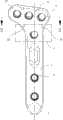
图2:本实用新型较佳实施例的平面图。Fig. 2: Plan view of the preferred embodiment of the utility model.
图3:图23-3剖线的剖面图。Figure 3: Sectional view of Figure 23-3.
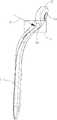
图4:本实用新型较佳实施例的侧视图。Fig. 4: The side view of the preferred embodiment of the utility model.
【主要组件符号说明】[Description of main component symbols]
1 身部 11 锁孔1
2 头部 21 穿孔2
L 中线L midline
Z 连接处Z junction
B1 大曲率侧B1 Large curvature side
B2 小曲率侧B2 small curvature side
S 基准面S datum plane
A1、A2、A3 弧度。A1, A2, A3 radians.
具体实施方式Detailed ways
为让本实用新型的上述及其它目的、特征及优点能更明显易懂,下文特举本实用新型的较佳实施例,并配合附图,作详细说明如下:In order to make the above and other purposes, features and advantages of the present utility model more obvious and understandable, the preferred embodiments of the present utility model are specially cited below, together with the accompanying drawings, for detailed description as follows:
请参照图1所示,本实用新型较佳实施例的胫骨近端骨板可由外科等级的不锈钢、钛金属或钛合金所制成,但不以上述材质为限;该胫骨近端骨板包含相连接的一身部1及一头部2。Please refer to Fig. 1, the proximal tibial bone plate of the preferred embodiment of the present invention can be made of surgical grade stainless steel, titanium metal or titanium alloy, but not limited to the above materials; the proximal tibial bone plate includes A connected
请配合参照图2所示,该身部1概呈长型扁板,具有一纵长向及一短向,该短向正交于该纵长向,该身部1沿该纵长向具有一中线L,该中线L通过该身部1在该短向上的中点。该身部1另设有数个锁孔11,该数个锁孔11沿该身部1的纵长向排列且间隔分布,该数个锁孔11的轴心较佳可通过该中线L,使该身部1被锁合于骨头上时,能对骨头施予较平均的压合力。Please refer to FIG. 2, the
该头部2也是概呈长型的扁板,具有互呈正交的一纵长向及一短向,该头部2可选择以一短向侧一体连接于该身部1的一纵长向端部,以强化该头部2与身部1的连接处Z的结构强度;其中,该身部1与头部2的纵长向夹角不限,可互呈垂直或不垂直,而该连接处Z则可以由该头部2渐缩宽度地向该身部1延伸,使该连接处Z的两侧呈连续的凹弧状以避免应力集中。在本实施例中,该连接处Z的一侧具有较大的曲率而形成大曲率侧B1,另一侧的曲率则相对较小而形成小曲率侧B2;该头部2另设有数个穿孔21,该数个穿孔21可以沿该头部2的纵长向排列且间隔分布。其中,一基准面S通过该头部2,该基准面S垂直于该中线L,并通过该数个穿孔21之中最邻近该大曲率侧B1的穿孔21的轴心。The
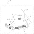
本实用新型经随机取样120位华人的胫骨外形资料,经统计后取得一平均胫骨模型,并使本实用新型的胫骨近端骨板具有可贴合于该平均胫骨模型的胫骨近端后侧处的预设弧度,使该胫骨近端骨板可于手术时,直接贴合于患者的胫骨近端后侧处,以减少术前需花费时间大幅度地调整骨板外形的情况。The utility model obtains an average tibia model through random sampling of the tibial shape data of 120 Chinese, and makes the tibial proximal bone plate of the present utility model have the rear side of the tibial proximal end that can fit on the average tibial model The preset curvature allows the proximal tibia bone plate to fit directly on the posterior side of the patient’s proximal tibia during surgery, reducing the need to spend a lot of time adjusting the shape of the bone plate before surgery.
请参照图2、3所示,该胫骨近端骨板的头部2于该基准面S上具有数个连续的弧度;在本实施例中,该弧度的数量可以为两个,对位至该大曲率侧B1的弧度A1的曲率半径可以为47±5 mm,另一弧度A2的曲率半径可以为18±5mm。Please refer to Figures 2 and 3, the
请参照图2、4所示,在本实施例中,还可以使该头部2对应于该小曲率侧B2且与该基准面S相接处的弧度A3的曲率半径为19±5 mm;如此,可更进一步地提升该胫骨近端骨板与患者胫骨近端后侧处的贴合度。Please refer to Figures 2 and 4, in this embodiment, the radius of curvature of the arc A3 of the
综上所述,本实用新型的胫骨近端骨板,具有预设弧度,可直接贴合于胫骨近端后侧处,以减少术前大幅度地调整骨板外形的情况,可提升手术效率;更重要的是,该胫骨近端骨板可减少因扳折而产生的变形,使该胫骨近端骨板与骨钉之间得以维持良好的锁固密合度,避免术后产生该胫骨近端骨板松脱或摇晃的状况,具有提升手术治疗效果的功效。In summary, the proximal tibia bone plate of the present invention has a preset radian and can be directly attached to the posterior side of the proximal tibia to reduce the situation of greatly adjusting the shape of the bone plate before surgery and improve surgical efficiency. more importantly, the proximal tibial bone plate can reduce the deformation caused by pulling, so that the proximal tibial bone plate and the bone nail can maintain a good locking tightness, and avoid the occurrence of the proximal tibial bone plate after surgery. If the end bone plate is loose or shaking, it can improve the effect of surgical treatment.
只是以上所述,仅为本实用新型的较佳实施例而已,当不能以此限定本实用新型实施范围;故,凡依本实用新型申请专利范围及创作说明书内容所作的简单的等效变化与修饰,皆应仍属本实用新型专利涵盖之范围内。Only the above is only a preferred embodiment of the present utility model, and should not limit the scope of implementation of the present utility model with this; Modifications should still fall within the scope covered by the utility model patent.
Claims (6)
Applications Claiming Priority (2)
| Application Number | Priority Date | Filing Date | Title |
|---|---|---|---|
| TW101210256UTWM439463U (en) | 2012-05-29 | 2012-05-29 | Proximal tibia bone plate |
| TW101210256 | 2012-05-29 |
Publications (1)
| Publication Number | Publication Date |
|---|---|
| CN202637084Utrue CN202637084U (en) | 2013-01-02 |
Family
ID=47406275
Family Applications (1)
| Application Number | Title | Priority Date | Filing Date |
|---|---|---|---|
| CN2012202607710UExpired - Fee RelatedCN202637084U (en) | 2012-05-29 | 2012-06-05 | Proximal tibia fragment plate |
Country Status (2)
| Country | Link |
|---|---|
| CN (1) | CN202637084U (en) |
| TW (1) | TWM439463U (en) |
Cited By (2)
| Publication number | Priority date | Publication date | Assignee | Title |
|---|---|---|---|---|
| CN103417284A (en)* | 2013-09-04 | 2013-12-04 | 王晓宁 | Tibial plateau back outer side bone plate |
| CN105395242A (en)* | 2015-11-16 | 2016-03-16 | 上海交通大学医学院附属新华医院 | Proximal tibia fracture plate system |
- 2012
- 2012-05-29TWTW101210256Upatent/TWM439463U/ennot_activeIP Right Cessation
- 2012-06-05CNCN2012202607710Upatent/CN202637084U/ennot_activeExpired - Fee Related
Cited By (3)
| Publication number | Priority date | Publication date | Assignee | Title |
|---|---|---|---|---|
| CN103417284A (en)* | 2013-09-04 | 2013-12-04 | 王晓宁 | Tibial plateau back outer side bone plate |
| CN105395242A (en)* | 2015-11-16 | 2016-03-16 | 上海交通大学医学院附属新华医院 | Proximal tibia fracture plate system |
| CN105395242B (en)* | 2015-11-16 | 2018-01-09 | 上海交通大学医学院附属新华医院 | A kind of proximal tibia bone plate system |
Also Published As
| Publication number | Publication date |
|---|---|
| TWM439463U (en) | 2012-10-21 |
Similar Documents
| Publication | Publication Date | Title |
|---|---|---|
| CN202908830U (en) | Plate for fracture treatment | |
| US8652179B2 (en) | Bone plate extender and extension system for bone restoration and methods of use thereof | |
| US8628533B2 (en) | Bone plate with reduction aids and methods of use thereof | |
| JP2003530138A (en) | Osteosynthesis bone plate | |
| CA2946034C (en) | Bone plate system for hand fractures and other small bones | |
| JP4971195B2 (en) | Plates and screws for fracture treatment | |
| CN1832706B (en) | Bone plate | |
| CN104159528B (en) | For inserting the nail of the surgical operation suturing in bone | |
| JP2002248110A (en) | Spinal fusion device | |
| CA2539386A1 (en) | Anatomical distal radius fracture fixation plate and methods of using the same | |
| JP2009542279A (en) | Bone plate with compound adjustment holes joined by open space | |
| JPH08503633A (en) | Bone fixation plate | |
| WO2012119112A2 (en) | Modular and non-modular cortical buttress device | |
| CN105848599B (en) | bone plate | |
| WO2006111096A1 (en) | Bone plate with centric hooks | |
| US20130053899A1 (en) | Bone plate with hook portion | |
| CN202637084U (en) | Proximal tibia fragment plate | |
| CN100542497C (en) | Osteosynthesis plate | |
| JP2011019710A (en) | Plate for fixing clavicula | |
| CN204765868U (en) | Stress dissipation type locking pressurizing coaptation board | |
| JP3146826U (en) | Bone fixation member and bone fixation system | |
| JP2020049387A (en) | Locking web plate | |
| CN213047093U (en) | U-shaped nail fixing system for fixing tendon and ligament bone surface | |
| CN215458541U (en) | Anatomical locking steel plate for fixing outer side edge of scapula | |
| CN211704800U (en) | Scapula fracture is with dissecting type hone lamella |
Legal Events
| Date | Code | Title | Description |
|---|---|---|---|
| C14 | Grant of patent or utility model | ||
| GR01 | Patent grant | ||
| CF01 | Termination of patent right due to non-payment of annual fee | Granted publication date:20130102 Termination date:20150605 | |
| EXPY | Termination of patent right or utility model |