CN202631620U - Optical module intelligent test board - Google Patents
Optical module intelligent test boardDownload PDFInfo
- Publication number
- CN202631620U CN202631620UCN 201220219601CN201220219601UCN202631620UCN 202631620 UCN202631620 UCN 202631620UCN 201220219601CN201220219601CN 201220219601CN 201220219601 UCN201220219601 UCN 201220219601UCN 202631620 UCN202631620 UCN 202631620U
- Authority
- CN
- China
- Prior art keywords
- module
- monitoring
- test
- mcu
- supply voltage
- Prior art date
- Legal status (The legal status is an assumption and is not a legal conclusion. Google has not performed a legal analysis and makes no representation as to the accuracy of the status listed.)
- Expired - Fee Related
Links
- 238000012360testing methodMethods0.000titleclaimsabstractdescription50
- 230000003287optical effectEffects0.000titleclaimsabstractdescription13
- 238000012544monitoring processMethods0.000claimsabstractdescription45
- 230000001105regulatory effectEffects0.000claimsabstract4
- 238000005070samplingMethods0.000claimsdescription10
- 230000005540biological transmissionEffects0.000claimsdescription3
- 238000013154diagnostic monitoringMethods0.000claimsdescription3
- 230000008054signal transmissionEffects0.000abstractdescription4
- 238000010586diagramMethods0.000description6
- 238000000034methodMethods0.000description3
- 239000003990capacitorSubstances0.000description2
- 238000004891communicationMethods0.000description2
- 238000001514detection methodMethods0.000description2
- 230000009286beneficial effectEffects0.000description1
- 238000013461designMethods0.000description1
Images


Landscapes
- Tests Of Electronic Circuits (AREA)
Abstract
Description
Translated fromChinese技术领域technical field
本实用新型设计涉及数字模块测试领域,具体涉及一种光模块智能测试板。The design of the utility model relates to the field of digital module testing, in particular to an optical module intelligent testing board.
背景技术Background technique
现有的光通信用数字模块测试板,在测试过程中,需要过多的辅助设备,而且很多参数不能很方便的改变和检测,如输入模块的电压和模块的电流。这样给我们测试带来了很大的不便,使测试变得繁琐和耗时。Existing digital module test boards for optical communication require too much auxiliary equipment during the test process, and many parameters cannot be easily changed and detected, such as the voltage of the input module and the current of the module. This brings great inconvenience to our test, making the test cumbersome and time-consuming.
实用新型内容Utility model content
本实用新型的目的在于:为了解决上述现有技术的问题,提供一种简化测试所需模块的,使用方便,操作简单的光模块智能测试板。The purpose of this utility model is: in order to solve the above-mentioned problems in the prior art, provide an optical module intelligent test board which simplifies the modules required for testing, is easy to use and easy to operate.
为了实现上述目的,本实用新型的技术方案为:In order to achieve the above object, the technical solution of the utility model is:
一种光模块智能测试板,包括板底和电子模块,电子模块镶嵌在板底上,该电子模块包括MCU(Micro Controller Unit)微控制器、DDM(Digital Diagnostic Monitoring)监控模块、电流监控模块、可调供电电压模块及模块参数调节块,DDM监控模块、电流监控模块、可调供电电压模块及模块参数调节块分别通过传输线与MCU微控制器连接。本实用新型实现了实时调节电压大小、实时监控、高速信号传输等功能;可以方便快捷的对测试模块进行监控,并且可直接监控出电流。包括PON模块、SFP模块等数字模块的测试都可以使用此测试板。它所使用的外部设备大大减少,并且可以直接监控电流、在线改变供电电压以及实时监控模块的状态。大大加快了测试速度以及测试精度。An optical module intelligent test board comprises a board bottom and an electronic module, the electronic module is embedded on the board bottom, and the electronic module includes an MCU (Micro Controller Unit) microcontroller, a DDM (Digital Diagnostic Monitoring) monitoring module, a current monitoring module, The adjustable supply voltage module and the module parameter adjustment block, the DDM monitoring module, the current monitoring module, the adjustable supply voltage module and the module parameter adjustment block are respectively connected to the MCU microcontroller through the transmission line. The utility model realizes the functions of real-time voltage adjustment, real-time monitoring, high-speed signal transmission, etc.; the test module can be monitored conveniently and quickly, and the current can be directly monitored. This test board can be used for testing digital modules such as PON modules and SFP modules. The external equipment it uses is greatly reduced, and it can directly monitor the current, change the supply voltage online and monitor the status of the module in real time. Greatly speed up the test speed and test accuracy.
作为本实用新型的进一步改进,MCU微控制器通过I2C(Inter-Integrated Circuit)总线与测试模块通信。利用I2C总线进行通信,实现远程监控。As a further improvement of the utility model, the MCU microcontroller communicates with the test module through the I2C (Inter-Integrated Circuit) bus. Use the I2C bus to communicate and realize remote monitoring.
作为本实用新型的进一步改进,MCU微控制器通过USB连接线与上位机进行通信,实现远程监控进行测试模块与测试板进行通信。MCU微控制器与上位机进行通信,使上位机更好的控制调节MCU微控制器。As a further improvement of the utility model, the MCU micro-controller communicates with the upper computer through the USB connection line, realizes remote monitoring and the test module communicates with the test board. The MCU microcontroller communicates with the host computer, so that the host computer can better control and adjust the MCU microcontroller.
作为本实用新型的进一步改进,DDM监控模块包括多个监控LED指示,包括电源、数据、突发、TX_SD、LOS、TX_Fault监测指示灯。利用各个监测指示灯,更好的及时调控各元件,使其工作在正常范围内。As a further improvement of the utility model, the DDM monitoring module includes a plurality of monitoring LED indications, including power supply, data, burst, TX_SD, LOS, and TX_Fault monitoring indicator lights. Use each monitoring indicator light to better control each component in time to make it work within the normal range.
作为本实用新型的进一步改进,该电流监控模块由检测电阻、采样电阻、电容及ADC(模数变换器)构成。As a further improvement of the utility model, the current monitoring module is composed of a detection resistor, a sampling resistor, a capacitor and an ADC (Analog-to-Digital Converter).
作为本实用新型的进一步改进,该可调供电电压模块由LDO(low dropout regulator)低压差线性稳压器、采样电阻及AD构成。可以通过对MCU微控制器进行控制从而实现对供电电压的调节,MCU微控制器通过对电阻两端进行采样,从而计算出模块电流大小。As a further improvement of the utility model, the adjustable supply voltage module is composed of an LDO (low dropout regulator) low dropout linear voltage regulator, a sampling resistor and an AD. The power supply voltage can be adjusted by controlling the MCU microcontroller, and the MCU microcontroller can calculate the module current by sampling both ends of the resistor.
本实用新型的有益效果在于:本实用新型构造这样的一种结构,简化测试所需模块的,使用的外部设备大大减少,使用方便,可以方便快捷的对测试模块进行监控,并且可直接监控出电流,操作简单,实现了实时调节电压大小、实时监控、高速信号传输等功能,大大加快了测试速度以及测试精度。The beneficial effects of the utility model are: the utility model has such a structure, which simplifies the modules required for the test, greatly reduces the external equipment used, is convenient to use, can monitor the test modules conveniently and quickly, and can directly monitor the Current, easy to operate, realize real-time voltage adjustment, real-time monitoring, high-speed signal transmission and other functions, greatly speeding up the test speed and test accuracy.
附图说明Description of drawings
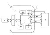
图1为本实用新型的工作原理示意图。Fig. 1 is a schematic diagram of the working principle of the utility model.
图2为本实用新型的电流监控模块电流第一种监控方式示意图。FIG. 2 is a schematic diagram of the first monitoring mode of the current monitoring module of the present invention.
图3为本实用新型的电流监控模块电流第二种监控方式示意图。FIG. 3 is a schematic diagram of the second monitoring mode of the current monitoring module of the present invention.
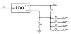
图4为本实用新型的可调供电电压模块第一种调压方式示意图.Fig. 4 is a schematic diagram of the first voltage regulation mode of the adjustable power supply voltage module of the present invention.
图5为本实用新型的可调供电电压模块第二种调压方式示意图。FIG. 5 is a schematic diagram of the second voltage regulation mode of the adjustable power supply voltage module of the present invention.
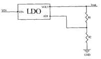
图6为本实用新型的可调供电电压模块第三种调压方式示意图。FIG. 6 is a schematic diagram of the third voltage regulation mode of the adjustable power supply voltage module of the present invention.
具体实施方式Detailed ways
参照图1所示,一种光模块智能测试板,包括板底1和电子模块2,电子模块2镶嵌在板底1上,该电子模块2包括MCU(MicroController Unit)微控制器21、DDM(Digital Diagnostic Monitoring)监控模块22、电流监控模块23、可调供电电压模块24及模块参数调节块25,DDM监控模块22、电流监控模块23、可调供电电压模块24及模块参数调节块25分别通过传输线与MCU微控制器21连接。本实用新型实现了实时调节电压大小、实时监控、高速信号传输等功能;可以方便快捷的对测试模块进行监控,并且可直接监控出电流。包括PON模块、SFP模块等数字模块的测试都可以使用此测试板。它所使用的外部设备大大减少,并且可以直接监控电流、在线改变供电电压以及实时监控模块的状态。大大加快了测试速度以及测试精度。With reference to shown in Fig. 1, a kind of optical module intelligent test board comprises
MCU微控制器21通过I2C(Inter-Integrated Circuit)总线31与测试模块5通信。利用I2C总线31进行通信,实现远程监控。
MCU微控制器21通过USB连接线32与上位机4进行通信,实现远程监控进行测试模块5与测试板进行通信。MCU微控制器21与上位机4进行通信,使上位机4更好的控制调节MCU微控制器21。The
DDM监控模块22包括多个监控LED指示,包括电源、数据、突发、TX_SD、LOS、TX_Fault监测指示灯。利用各个监测指示灯,更好的及时调控各元件,使其工作在正常范围内。The
该电流监控模块23由检测电阻、采样电阻、电容及ADC(模数变换器)构成。The
该可调供电电压模块24由LDO(low dropout regulator)低压差线性稳压器、采样电阻及AD构成。可以通过对MCU微控制器21进行控制从而实现对供电电压的调节,MCU微控制器21通过对电阻两端进行采样,从而计算出模块电流大小。The adjustable
采用了电阻采样电压的方法,计算出流经测试板的电流,进而计算出测试模块5的电流;采用可调电源芯片以及MCU微控制器21控制,使供给测试模块5的电压可以进行电压调节。并且使测试模块5供电电压更加稳定、精确。The method of sampling voltage by resistance is used to calculate the current flowing through the test board, and then calculate the current of the
电流监控模块23的电流监控方式如下:The current monitoring mode of the
参照图2所示,通过R1、R2、R3并联来获得所需要的阻值,再通过ADC_CRT+、ADC_CRT-进行电压采样,假设R4=R5;R6=R7,可计算出测试模块5电流值为:(R4+R6)*(VADC_CRT+-VADC_CRT-)/[(R1//R2//R3)*R6],通过此公式可以算出测试模块5电流值;参照图3所示,测试模块5电流经过R1产生压差,电压差经过运放进行放大,再经过镜像电流源按一定比例进行镜像,进而产生相应的电压,最后经过MCU微控制器21计算出测试模块5电流值。Referring to Figure 2, the required resistance value is obtained by connecting R1, R2, and R3 in parallel, and then voltage sampling is performed through ADC_CRT+, ADC_CRT-, assuming R4=R5; R6=R7, the current value of the
可调供电电压模块24的电压调节方式如下:The voltage regulation mode of the adjustable
参照图4所示,MCU微控制器21通过对VCTRL1、VCTRL2、VCTRL3、VCTRL4四个端口进行控制,以此来改变ADJ到地的电阻值,进而可以调节输出电压值;参照图5所示,通过MCU微控制器21改变DA电压值来调节输出电压值;参照图6所示,通过对R1、R2电阻值调节来改变ADJ的电压值,进而可以调节输出电压值。Referring to FIG. 4, the
Claims (6)
Priority Applications (1)
| Application Number | Priority Date | Filing Date | Title |
|---|---|---|---|
| CN 201220219601CN202631620U (en) | 2012-05-15 | 2012-05-15 | Optical module intelligent test board |
Applications Claiming Priority (1)
| Application Number | Priority Date | Filing Date | Title |
|---|---|---|---|
| CN 201220219601CN202631620U (en) | 2012-05-15 | 2012-05-15 | Optical module intelligent test board |
Publications (1)
| Publication Number | Publication Date |
|---|---|
| CN202631620Utrue CN202631620U (en) | 2012-12-26 |
Family
ID=47384810
Family Applications (1)
| Application Number | Title | Priority Date | Filing Date |
|---|---|---|---|
| CN 201220219601Expired - Fee RelatedCN202631620U (en) | 2012-05-15 | 2012-05-15 | Optical module intelligent test board |
Country Status (1)
| Country | Link |
|---|---|
| CN (1) | CN202631620U (en) |
Cited By (6)
| Publication number | Priority date | Publication date | Assignee | Title |
|---|---|---|---|---|
| CN104515951A (en)* | 2014-11-27 | 2015-04-15 | 北京航天测控技术有限公司 | Board-level embedded test controller and board-level embedded test method |
| CN105760318A (en)* | 2016-02-16 | 2016-07-13 | 烽火通信科技股份有限公司 | Method for reading and writing optical module register on basis of Linux system |
| CN106788692A (en)* | 2016-12-15 | 2017-05-31 | 武汉电信器件有限公司 | A kind of test equipment and its method of testing of module LOS |
| CN106936496A (en)* | 2017-04-20 | 2017-07-07 | 江苏奥雷光电有限公司 | Multiple IIC communication equipments hot plug devices |
| CN107543951A (en)* | 2016-06-24 | 2018-01-05 | 中兴通讯股份有限公司 | A kind of optical module on-Line Voltage detection means and method |
| CN107966269A (en)* | 2017-11-14 | 2018-04-27 | 东莞铭普光磁股份有限公司 | Optical module and optical device state monitoring system |
- 2012
- 2012-05-15CNCN 201220219601patent/CN202631620U/ennot_activeExpired - Fee Related
Cited By (6)
| Publication number | Priority date | Publication date | Assignee | Title |
|---|---|---|---|---|
| CN104515951A (en)* | 2014-11-27 | 2015-04-15 | 北京航天测控技术有限公司 | Board-level embedded test controller and board-level embedded test method |
| CN105760318A (en)* | 2016-02-16 | 2016-07-13 | 烽火通信科技股份有限公司 | Method for reading and writing optical module register on basis of Linux system |
| CN107543951A (en)* | 2016-06-24 | 2018-01-05 | 中兴通讯股份有限公司 | A kind of optical module on-Line Voltage detection means and method |
| CN106788692A (en)* | 2016-12-15 | 2017-05-31 | 武汉电信器件有限公司 | A kind of test equipment and its method of testing of module LOS |
| CN106936496A (en)* | 2017-04-20 | 2017-07-07 | 江苏奥雷光电有限公司 | Multiple IIC communication equipments hot plug devices |
| CN107966269A (en)* | 2017-11-14 | 2018-04-27 | 东莞铭普光磁股份有限公司 | Optical module and optical device state monitoring system |
Similar Documents
| Publication | Publication Date | Title |
|---|---|---|
| CN202631620U (en) | Optical module intelligent test board | |
| CN204166424U (en) | Simple intelligent High-accuracy direct current electronic load | |
| CN202676817U (en) | Low dropout regulator testing device | |
| CN201096867Y (en) | Multi-function tester for measuring semiconductor silicon material P/N and resistance rate | |
| CN205749851U (en) | A kind of intelligent DC electronic load based on MSP430G2553 | |
| CN203773034U (en) | Testing device of direct-current ripple system | |
| CN103712686A (en) | Light intensity detecting device | |
| CN203759570U (en) | Intelligent control apparatus for greenhouse | |
| CN204214944U (en) | A kind of general radio frequency condition monitoring and fault diagnosis warning device | |
| CN102789251B (en) | Current adjustable constant current circuit | |
| CN105629072A (en) | System for measuring multiplex resistance | |
| CN103592786A (en) | Auto-Flicker automatic tuning method for liquid crystal module | |
| CN216518786U (en) | Multi-channel general temperature and fan control monitoring module | |
| CN202903459U (en) | Laser assembly test tooling | |
| CN204166076U (en) | A kind of Multifunction silicon controlled tester being applied to big current rectifying installation | |
| CN201060232Y (en) | current mutual inductor testing apparatus for intelligent electrical apparatus release | |
| CN207382651U (en) | A kind of constant current driving system of stabilized light source | |
| CN211979009U (en) | Constant current source device for engine test bench | |
| CN203811778U (en) | A motor running state monitoring device | |
| CN114839430A (en) | Isolation power supply voltage acquisition circuit based on isolation operational amplifier | |
| CN209044347U (en) | A kind of simulation generates the device of multichannel pressure signal | |
| CN102291880B (en) | A kind of LED drive chip of low-voltage | |
| CN204177929U (en) | A kind of window shutter thermorelay pick-up unit for diesel locomotive | |
| CN203191532U (en) | Automatic control type electronic load current aging device | |
| CN203772411U (en) | Light intensity detection device |
Legal Events
| Date | Code | Title | Description |
|---|---|---|---|
| C14 | Grant of patent or utility model | ||
| GR01 | Patent grant | ||
| CF01 | Termination of patent right due to non-payment of annual fee | ||
| CF01 | Termination of patent right due to non-payment of annual fee | Granted publication date:20121226 Termination date:20190515 |