CN202600581U - Electronic device with sliding mechanism - Google Patents
Electronic device with sliding mechanismDownload PDFInfo
- Publication number
- CN202600581U CN202600581UCN 201220216282CN201220216282UCN202600581UCN 202600581 UCN202600581 UCN 202600581UCN 201220216282CN201220216282CN 201220216282CN 201220216282 UCN201220216282 UCN 201220216282UCN 202600581 UCN202600581 UCN 202600581U
- Authority
- CN
- China
- Prior art keywords
- housing
- base
- slide block
- slider
- sliding mechanism
- Prior art date
- Legal status (The legal status is an assumption and is not a legal conclusion. Google has not performed a legal analysis and makes no representation as to the accuracy of the status listed.)
- Expired - Lifetime
Links
Images


Landscapes
- Casings For Electric Apparatus (AREA)
Abstract
Translated fromChinese
Description
Translated fromChinese技术领域technical field
本实用新型涉及一种具有滑动机构的电子装置,且特别涉及一种具有滑动机构,且其操作平顺度较佳的电子装置。The utility model relates to an electronic device with a sliding mechanism, in particular to an electronic device with a sliding mechanism and better operating smoothness.
背景技术Background technique
传统的笔记型电脑具有一枢转机构,设置于上壳体与下壳体之间。随着使用者的操作,上壳体可通过枢转机构相对下壳体翻转开合。其中一种笔记型电脑的枢转机构兼具滑行功能,因此当使用者欲开启笔记型电脑时,上壳体不但会相对下壳体翻转,同时间上壳体的底端亦会在下壳体的表面滑移,据此将笔记型电脑调整到最佳的操作视角。详细来说,传统的滑动式枢转机构利用滑块与滑槽的结合来达到驱使上壳体相对下壳体滑行的目的。然后传统滑动式枢转机构的滑块体积方正,其以面接触方式设置在滑槽内,随着上壳体的翻转,滑块易与滑槽产生大面积的非预期性碰撞,如此一来不但会大幅地降低传统滑动式枢转机构的使用寿命,亦会造成使用上的不顺,亦即使用者在驱动上壳体相对下壳体翻转滑移时会产生顿挫的手感。因此,如何设计提升操作流畅度的开合式笔记型电脑,即为相关机构产业的重点发展目标。A traditional notebook computer has a pivot mechanism disposed between the upper casing and the lower casing. With the user's operation, the upper case can be flipped open and closed relative to the lower case through the pivot mechanism. One of the notebook computers has a pivoting mechanism that also has a sliding function, so when the user wants to open the notebook computer, the upper casing will not only turn over relative to the lower casing, but at the same time the bottom of the upper casing will also be on the bottom of the lower casing. The surface glides to adjust the laptop to the best viewing angle for operation. In detail, the traditional sliding pivot mechanism utilizes the combination of the slider and the sliding slot to drive the upper casing to slide relative to the lower casing. Then the volume of the slider of the traditional sliding pivot mechanism is square, and it is arranged in the chute in a surface contact manner. With the turning of the upper casing, the slider will easily collide with the chute in a large area, so that Not only will the service life of the traditional sliding pivot mechanism be greatly reduced, but it will also cause inconvenience in use, that is, the user will feel frustrated when driving the upper casing to flip and slide relative to the lower casing. Therefore, how to design a foldable notebook computer that improves the fluency of operation is the key development goal of related organizations and industries.
实用新型内容Utility model content
本实用新型提供一种具有滑动机构,且其操作平顺度较佳的电子装置,以解决上述的问题。The utility model provides an electronic device with a sliding mechanism and better operating smoothness to solve the above problems.
本实用新型揭露一种具有滑动机构的电子装置,其包含有一第一壳体,一第二壳体,以可翻转方式设置于该第一壳体上,以及一滑动机构,设置于该第一壳体与该第二壳体之间。该滑动机构包含有一底座,设置于该第一壳体,以及一滑块,连接至该第二壳体。该第二壳体通过该滑块与该底座的一组合相对该第一壳体滑移。该底座包含有一滑槽结构与一导引槽结构。该滑块包含有一主体,以可滑动方式设置于该滑槽结构内,该主体的底部形成至少一凹陷槽。该滑块还包含有至少一个滚珠,以可活动方式设置于该凹陷槽内,以及一轴体,连接于该主体的旁侧。该轴体以可滑动方式插入该导引槽结构。该滑块通过该滚珠沿着一第一方向相对该底座移动。The utility model discloses an electronic device with a sliding mechanism, which includes a first casing, a second casing, which is reversibly arranged on the first casing, and a sliding mechanism, which is arranged on the first casing. between the housing and the second housing. The sliding mechanism includes a base, arranged on the first casing, and a sliding block, connected to the second casing. The second housing slides relative to the first housing through a combination of the slider and the base. The base includes a chute structure and a guide groove structure. The sliding block includes a main body, which is slidably arranged in the sliding groove structure, and at least one concave groove is formed on the bottom of the main body. The slider also includes at least one ball, which is movably arranged in the concave groove, and a shaft, which is connected to the side of the main body. The shaft body is slidably inserted into the guide groove structure. The slider moves relative to the base along a first direction through the ball.
本实用新型另揭露该滑块通过该滚珠以点接触方式相对该底座移动。The utility model further discloses that the sliding block moves relative to the base in a point contact manner through the ball.
本实用新型另揭露该轴体限制该滑块沿着相异该第一方向的一方向相对该底座移动。According to the claimed invention, the shaft restricts the slider from moving relative to the base along a direction different from the first direction.
本实用新型另揭露该滑块还包含有一滚轮,套设于该轴体上,该轴体通过该滚轮相对该导引槽结构滑行。According to the claimed invention, the sliding block further includes a roller sheathed on the shaft, and the shaft slides relative to the guide groove structure through the roller.
本实用新型另揭露该滑块通过该滚轮以线接触方式相对该底座移动。The utility model further discloses that the sliding block moves relative to the base in a linear contact manner through the roller.
本实用新型另揭露该滑动机构还包含有一枢转支架,设置于该滑块上且连接至该第二壳体。该第二壳体通过该滑块与该枢转支架相对该第一壳体滑行并旋转。According to the claimed invention, the sliding mechanism further includes a pivot bracket disposed on the slider and connected to the second housing. The second housing slides and rotates relative to the first housing through the slider and the pivot bracket.
本实用新型另揭露该滑块还包含有一齿槽结构,设置于该主体的表面。该滑动机构还包含有一闩锁件,以可活动方式设置于该底座上。该闩锁件用来卡合于该齿槽结构,以限制该滑块相对该底座的移动。According to the claimed invention, the sliding block further includes an alveolar structure disposed on the surface of the main body. The sliding mechanism also includes a latch, which is movably arranged on the base. The latch is used to engage with the tooth groove structure to limit the movement of the slider relative to the base.
本实用新型另揭露该齿槽结构包含有多个齿体,各齿体的顶端形成一导圆角,该闩锁件通过该导圆角以卡合于各相对应齿体。The utility model further discloses that the alveolar structure includes a plurality of tooth bodies, and a top end of each tooth body forms a rounded corner, and the latch member engages with each corresponding tooth body through the rounded corner.
本实用新型的滑动机构于滑块上装设多个滚珠及滚轮,分别以点接触方式和线接触方式有效降低滑块与底座之间的接触面积,达到提升滑动机构的操作流畅度的目的。此外,卡合结构的卡合端与齿槽结构的齿体的数量可视设计需求增设调整,其数量越多,闩锁件与滑块的可锁扣段数增加,第二壳体便可利用滑块机构达到多段式的视角固定功能。本实用新型的滑动机构的结构简单、操作容易,且具有低制造成本的优势,可广泛应用于各种类型具有上、下壳体开合或掀盖机制的电子装置。The sliding mechanism of the utility model is equipped with a plurality of balls and rollers on the slider, which effectively reduces the contact area between the slider and the base by means of point contact and line contact respectively, so as to achieve the purpose of improving the smoothness of the operation of the sliding mechanism. In addition, the number of the engaging end of the engaging structure and the teeth of the tooth groove structure can be adjusted according to the design requirements. The more the number is, the more the lockable segments of the latch and the slider increase, and the second housing can be used The slider mechanism achieves a multi-stage viewing angle fixing function. The sliding mechanism of the utility model has the advantages of simple structure, easy operation and low manufacturing cost, and can be widely used in various types of electronic devices with opening and closing mechanisms of upper and lower housings or flipping mechanisms.
附图说明Description of drawings
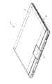
图1与图2分别为本实用新型实施例的电子装置于不同操作状态的示意图。FIG. 1 and FIG. 2 are schematic diagrams of an electronic device in different operating states according to an embodiment of the present invention.
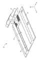
图3为本实用新型实施例的滑动机构的元件爆炸示意图。Fig. 3 is an exploded schematic view of components of the sliding mechanism of the embodiment of the present invention.
图4为本实用新型实施例的滑动机构的组立图。Fig. 4 is an assembly view of the sliding mechanism of the embodiment of the present invention.
图5为本实用新型实施例的电子装置于另一视角的示意图。FIG. 5 is a schematic diagram of an electronic device according to an embodiment of the present invention at another viewing angle.
图6为图5所示的电子装置的部分放大示意图。FIG. 6 is a partially enlarged schematic view of the electronic device shown in FIG. 5 .
其中,附图标记说明如下:Wherein, the reference signs are explained as follows:
10:电子装置10: Electronic device
12:第一壳体12: First shell
121:表面121: surface
14:第二壳体14: Second shell
141:底端141: bottom end
16:支撑板件16: Support plate
18:滑动机构18: sliding mechanism
20:底座20: base
22:滑块22: Slider
24:滑槽结构24: Chute structure
26:导引槽结构26: Guide groove structure
28:主体28: Subject
30:凹陷槽30: Depression groove
32:滚珠32: Ball
34:轴体34: Shaft body
36:滚轮36: Roller
38:枢转支架38: Pivot bracket
40:闩锁件40: Latch
401:卡合结构401: snap-fit structure
403:卡合端403: snap end
42:齿槽结构42: alveolar structure
421:齿体421: Teeth
423:导圆角423: Guide fillet
D1:第一方向D1: first direction
D2第二方向D2 second direction
D3:第三方向D3: Third direction
具体实施方式Detailed ways
请参阅图1与图2,图1与图2分别为本实用新型实施例的一电子装置10于不同操作状态的示意图。电子装置10包含有一第一壳体12、一第二壳体14、一支撑板件16以及一滑动机构18。电子装置10可为一掀盖式笔记型电脑,第一壳体12为下壳体,也即系统端,第二壳体14为上壳体,亦即荧幕端。第二壳体14以可翻转方式设置于第一壳体12上,使用者可调整荧幕端的视角。此外,第二壳体14相对第一壳体12翻转时,第二壳体14的一底端141会沿着第一壳体12的一表面121移动,并通过支撑板件16固定其翻转角度,如图2所示。因此,滑动机构18设置于第二壳体14的底端141与第一壳体12的表面121之间,第二壳体14利用支撑板件16与滑动机构18来达到相对第一壳体12翻转及滑移的目的。Please refer to FIG. 1 and FIG. 2 . FIG. 1 and FIG. 2 are schematic views of an
请参阅图3与图4,图3为本实用新型实施例的滑动机构18的元件爆炸示意图,图4为本实用新型实施例的滑动机构18的组立图。滑动机构18包含有一底座20以及一滑块22。底座20设置于第一壳体12,且底座20包含有一滑槽结构24与二导引槽结构26。滑块22以可动方式设置于底座20并连接至第二壳体14,因此第二壳体14可通过滑块22与底座20的一组合相对第一壳体12滑移。滑块22包含有一主体28,以可滑动方式设置于滑槽结构24,且主体28的底部形成有多个凹陷槽30。滑块22还包含有多个滚珠32,以可活动方式设置于各相对应凹陷槽30内,二轴体34,分别连接于主体28的两相对旁侧,以及二滚轮36,套设于各相对应主体28上。Please refer to FIG. 3 and FIG. 4 . FIG. 3 is an exploded view of components of the sliding
于此对滑动机构18的运作机制详细说明。为了减少滑块22相对底座20滑行时的接触面积,本实用新型安装多个滚珠32于主体28的凹陷槽30内。滚珠32会有部份体积凸出凹陷槽30,因此当滑块22相对底座20移动时,便可通过滚珠32以点接触方式连结至底座20产生相对移动,而滑块22的主体28则不会与底座20发生接触。此外,仅将滑块22放置于底座20的滑槽结构24内会造成滑块22在滑行过程中易左右晃动产生碰撞,故另需利用轴体34以可滑动方式插入其相对应的导引槽结构26内,以限制滑块22相对底座20的滑移方向,藉此提高滑动机构18的操作流畅度。举例来说,滑块22可利用滚珠32沿着一第一方向D1相对底座20移动,而轴体34与导引槽结构26的组合可有效限制滑块22沿着相异第一方向D1的一第二方向D2与一第三方向D3相对底座20移动,其中第二方向D2平行于底座20的表面且垂直第一方向D1,且第三方向D3为底座20的表面的法向量,因此轴体34的设置可有效避免滑块22在滑行过程中有左右晃动或上下振动的情况。Herein, the operation mechanism of the sliding
除此之外,为了降低轴体34与导引槽结构26内表面的接触面积,本实用新型的滑动机构18可另将滚轮36套接在轴体34上,因此当轴体34沿着导引槽结构26滑行时,便可通过滚轮36以线接触方式产生相对滑移。配合滚珠32与滚轮36的设计,本实用新型即可有效降低滑动机构18于操作时所产生的摩擦力,而使第二壳体14相对第一壳体12的翻转作动可平滑顺利。值得一提的是,本实用新型的滑动机构18的滑块22可不限于配置如前述实施例所述数量及位置的滚珠32与滚轮36。例如滑块22可选择性于主体28的底部及旁侧皆配置滚珠32或皆配置滚轮36,或可于主体28的底部配置滚轮36且于主体28旁侧配置滚珠32,其结构设计端视实际需求而定,故于此不再叙明。In addition, in order to reduce the contact area between the
如图1至图4所示,滑动机构18另可包含有一枢转支架38,设置于滑块22上且连接至第二壳体14。第二壳体14相对第一壳体12翻转时,由于第二壳体14的中段区域连接至支撑板件16的一侧,故随着其底端141通过滑动机构18相对第一壳体12平行移动,第二壳体14另可通过枢转支架38产生翻转动作,以将其显示荧幕面外露提供使用者观看。换句话说,本实用新型的滑动机构可通过其滑块22与底座20的组合、及枢转支架38与滑块22的组合,使得第二壳体14相对第一壳体12的翻转及滑行动作同步进行且相辅相成,例如当底端141随滑块22沿着底座20滑行的距离越长,第二壳体14相对第一壳体12的翻转角度会越大,便于使用者快速调整电子装置10的荧幕端视角。As shown in FIGS. 1 to 4 , the sliding
请参阅图5与图6,图5为本实用新型实施例的电子装置10于另一视角的示意图,图6为图5所示的电子装置10的部分放大示意图。滑动机构18另可包含有一闩锁件40,以可活动方式设置于底座20上,且闩锁件40的表面可具有一卡合结构401。滑块22另可包含有一齿槽结构42,设置于主体28的表面。齿槽结构42包含有多个齿体421,可嵌合于卡合结构401的多个卡合端403以产生干涉。当第二壳体14已相对第一壳体12调整至预设的视角,使用者可推动闩锁件40使其卡合于滑块22的齿槽结构42,以此限制滑块22相对底座20的移动,达到固定第二壳体14的翻转角度(荧幕端视角)的目的。再者,各齿体421的顶端可形成一导圆角423,其用途为了钝化齿体421的边缘,以使闩锁件40可将其卡合结构401平顺地卡合于各相对应齿体421。Please refer to FIG. 5 and FIG. 6 , FIG. 5 is a schematic view of the
相较于先前技术,本实用新型的滑动机构于滑块上装设多个滚珠及滚轮,分别以点接触方式和线接触方式有效降低滑块与底座之间的接触面积,达到提升滑动机构的操作流畅度的目的。此外,卡合结构的卡合端与齿槽结构的齿体的数量可视设计需求增设调整,其数量越多,闩锁件与滑块的可锁扣段数增加,第二壳体便可利用滑块机构达到多段式的视角固定功能。本实用新型的滑动机构的结构简单、操作容易,且具有低制造成本的优势,可广泛应用于各种类型具有上、下壳体开合或掀盖机制的电子装置。Compared with the prior art, the sliding mechanism of the present invention is equipped with a plurality of balls and rollers on the slider, which can effectively reduce the contact area between the slider and the base by point contact and line contact respectively, so as to achieve the operation of lifting the sliding mechanism purpose of fluency. In addition, the number of the engaging end of the engaging structure and the teeth of the tooth groove structure can be adjusted according to the design requirements. The more the number is, the more the lockable segments of the latch and the slider increase, and the second housing can be used The slider mechanism achieves a multi-stage viewing angle fixing function. The sliding mechanism of the utility model has the advantages of simple structure, easy operation and low manufacturing cost, and can be widely used in various types of electronic devices with opening and closing mechanisms of upper and lower housings or flipping mechanisms.
以上所述仅为本实用新型的较佳实施例,凡依本实用新型申请专利范围所做的均等变化与修饰,皆应属本实用新型的涵盖范围。The above descriptions are only preferred embodiments of the present utility model, and all equivalent changes and modifications made according to the patent scope of the present utility model shall fall within the scope of the present utility model.
Claims (8)
Applications Claiming Priority (2)
| Application Number | Priority Date | Filing Date | Title |
|---|---|---|---|
| TW101208210UTWM439973U (en) | 2012-05-02 | 2012-05-02 | Electronic device having a slide mechanism |
| TW101208210 | 2012-05-02 |
Publications (1)
| Publication Number | Publication Date |
|---|---|
| CN202600581Utrue CN202600581U (en) | 2012-12-12 |
Family
ID=47318111
Family Applications (1)
| Application Number | Title | Priority Date | Filing Date |
|---|---|---|---|
| CN 201220216282Expired - LifetimeCN202600581U (en) | 2012-05-02 | 2012-05-14 | Electronic device with sliding mechanism |
Country Status (2)
| Country | Link |
|---|---|
| CN (1) | CN202600581U (en) |
| TW (1) | TWM439973U (en) |
Cited By (3)
| Publication number | Priority date | Publication date | Assignee | Title |
|---|---|---|---|---|
| CN109246375A (en)* | 2018-11-23 | 2019-01-18 | 青岛海信电器股份有限公司 | A kind of sliding lid construction and laser television |
| CN112886114A (en)* | 2021-03-10 | 2021-06-01 | 惠州市忠邦电子有限公司 | Battery pack mounting box and battery pack mounting device |
| TWI790866B (en)* | 2021-12-21 | 2023-01-21 | 宏碁股份有限公司 | Foldable electronic deivce with multi-segment adjusting bracket |
- 2012
- 2012-05-02TWTW101208210Upatent/TWM439973U/ennot_activeIP Right Cessation
- 2012-05-14CNCN 201220216282patent/CN202600581U/ennot_activeExpired - Lifetime
Cited By (3)
| Publication number | Priority date | Publication date | Assignee | Title |
|---|---|---|---|---|
| CN109246375A (en)* | 2018-11-23 | 2019-01-18 | 青岛海信电器股份有限公司 | A kind of sliding lid construction and laser television |
| CN112886114A (en)* | 2021-03-10 | 2021-06-01 | 惠州市忠邦电子有限公司 | Battery pack mounting box and battery pack mounting device |
| TWI790866B (en)* | 2021-12-21 | 2023-01-21 | 宏碁股份有限公司 | Foldable electronic deivce with multi-segment adjusting bracket |
Also Published As
| Publication number | Publication date |
|---|---|
| TWM439973U (en) | 2012-10-21 |
Similar Documents
| Publication | Publication Date | Title |
|---|---|---|
| TWI518256B (en) | Hinge structure | |
| JP5517090B2 (en) | Portable electronic devices | |
| CN103869889B (en) | Rotating mechanism and related electronic device | |
| US9921610B2 (en) | Portable electronic device having supporter | |
| US9003607B1 (en) | Transmission device applied to rotary shafts | |
| CN103123523B (en) | Portable computer | |
| CN103576764B (en) | Sliding cover type electronic device and linear moving mechanism thereof | |
| CN102788080A (en) | Pivot device, keyboard seat with pivot device and portable electronic device | |
| CN104216471A (en) | Portable electronic device with lifting key module | |
| US20170192468A1 (en) | Computing device with a rotatable display member | |
| TWI519934B (en) | Docking device and electronic system therewith | |
| US10690285B2 (en) | Portable electronic device | |
| CN202600581U (en) | Electronic device with sliding mechanism | |
| CN104179792B (en) | Hinge mechanism and electronic device | |
| US20130128440A1 (en) | Portable Computer | |
| US8085532B2 (en) | Electronic device | |
| CN102340939B (en) | Flip cover type electronic device structure | |
| TWM444019U (en) | Driving mechanism for moving a display module relative to a host module and portable electronic device therewith | |
| JP2015121238A (en) | Biaxial hinge device | |
| US9383777B1 (en) | Notebook computer with lid mounting for translational movement | |
| CN103383593B (en) | fixing mechanism for fixing display module and portable electronic device thereof | |
| TWI576683B (en) | Computing device with a rotatable display member | |
| CN104156034A (en) | Portable electronic device and hinge assembly thereof | |
| TW201724948A (en) | Portable electronic device | |
| TW201336391A (en) | Sliding device of a clamshell electronic product |
Legal Events
| Date | Code | Title | Description |
|---|---|---|---|
| C14 | Grant of patent or utility model | ||
| GR01 | Patent grant | ||
| CX01 | Expiry of patent term | Granted publication date:20121212 | |
| CX01 | Expiry of patent term |