CN202593676U - Three-wheel-foot type serial-parallel combined robot - Google Patents
Three-wheel-foot type serial-parallel combined robotDownload PDFInfo
- Publication number
- CN202593676U CN202593676UCN 201220133929CN201220133929UCN202593676UCN 202593676 UCN202593676 UCN 202593676UCN 201220133929CN201220133929CN 201220133929CN 201220133929 UCN201220133929 UCN 201220133929UCN 202593676 UCN202593676 UCN 202593676U
- Authority
- CN
- China
- Prior art keywords
- joint
- wheel
- pitching
- carrying platform
- roll
- Prior art date
- Legal status (The legal status is an assumption and is not a legal conclusion. Google has not performed a legal analysis and makes no representation as to the accuracy of the status listed.)
- Expired - Lifetime
Links
Images


Landscapes
- Manipulator (AREA)
Abstract
Description
Translated fromChinese技术领域technical field
本实用新型属于多足步行机器人领域,尤其是涉及一种三轮足式串并混联机器人机构。The utility model belongs to the field of multi-legged walking robots, in particular to a three-wheel-legged series-parallel hybrid robot mechanism.
技术背景technical background
目前国内外机器人的行走机构按移动方式可以分为轮式、腿式、履带式等。然而,它们各自都存在着相应的缺陷,轮式结构速度快,控制灵活,但越障能力有限。腿式结构适应能力强,观赏性也好,但能耗大,控制复杂,且不适于对灵活性、快速性要求高的场合。履带式移动机器人重量大,能耗高等。At present, the walking mechanism of domestic and foreign robots can be divided into wheel type, leg type, crawler type and so on according to the moving mode. However, there are corresponding defects in each of them. The wheeled structure is fast and flexible in control, but its ability to overcome obstacles is limited. The leg structure has strong adaptability and good ornamental value, but it consumes a lot of energy, and the control is complicated, and it is not suitable for occasions that require high flexibility and rapidity. Tracked mobile robots are heavy in weight and consume high energy consumption.
发明内容Contents of the invention
为了克服移动行走机器人不能兼顾结构简单、灵活性和快速性的不足,本实用新型提出了一种在简化结构的同时,具有良好的灵活性和快速性的三轮足式串并混联机器人。In order to overcome the shortcoming that the mobile walking robot cannot take into account the disadvantages of simple structure, flexibility and rapidity, the utility model proposes a three-wheeled series-parallel hybrid robot with good flexibility and rapidity while simplifying the structure.
为了解决上述技术问题提出的技术方案为:The technical scheme proposed in order to solve the above technical problems is:
一种三轮足式串并混联机器人,所述三轮足式串并混联机器人包括运载平台、电池、控制系统、摄像头和3个6自由度的轮足组合式运动支链,所述运载平台上安装电池、控制系统和摄像头,在所述运载平台下方安装所述轮足组合式运动支链,所述轮足组合式运动支链包括偏航关节、偏航关节支架、上俯仰关节、大腿、中俯仰关节、中俯仰关节支架,上横滚关节、小腿、下俯仰关节、下俯仰关节支架、下横滚关节、动力轮支架和动力轮,所述偏航关节与所述运载平台下方固定连接,所述偏航关节安装在偏航关节支架上方,所述偏航关节支架侧边安装上俯仰关节,上俯仰关节与大腿上端固定连接,所述大腿下端与中俯仰关节连接,所述中俯仰关节安装在中俯仰关节支架上,所述中俯仰关节支架与下横滚关节连接,所述下横滚关节与小腿上端连接,所述小腿下端与下俯仰关节连接,所述下俯仰关节安装在下俯仰关节支架上,所述下俯仰关节支架与下横滚关节连接,所述下横滚关节与动力轮支架连接,所述动力轮支架上安装动力轮。A three-wheel-footed series-parallel hybrid robot, the three-wheel-footed serial-parallel hybrid robot includes a carrier platform, a battery, a control system, a camera, and three 6-degree-of-freedom wheel-foot combined motion branch chains, the A battery, a control system and a camera are installed on the carrying platform, and the wheel-foot combined motion branch chain is installed under the carrying platform, and the wheel-foot combined motion branch chain includes a yaw joint, a yaw joint bracket, and an upper pitch joint , thigh, middle pitch joint, middle pitch joint bracket, upper roll joint, calf, lower pitch joint, lower pitch joint bracket, lower roll joint, power wheel bracket and power wheel, the yaw joint and the carrying platform The bottom is fixedly connected, the yaw joint is installed above the yaw joint support, the upper pitch joint is installed on the side of the yaw joint support, the upper pitch joint is fixedly connected with the upper end of the thigh, and the lower end of the thigh is connected with the middle pitch joint. The middle pitch joint is installed on the middle pitch joint support, the middle pitch joint support is connected with the lower roll joint, the lower roll joint is connected with the upper end of the lower leg, the lower end of the lower leg is connected with the lower pitch joint, and the lower pitch joint is connected with the upper end of the lower leg. The joint is installed on the lower pitch joint support, the lower pitch joint support is connected with the lower roll joint, the lower roll joint is connected with the power wheel support, and the power wheel is installed on the power wheel support.
进一步,所述偏航关节、上俯仰关节、中俯仰关节、上横滚关节、下俯仰关节、下横滚关节均采用旋转关节,所述旋转关节包括关节外壳、左端输出轴承、左端盖、绝对编码器固定套筒、绝对编码器、输出法兰、波发生器椭圆塞、波发生器轴承、柔轮、钢轮、固定架、键、输入法兰、行星轮变速器、套筒、直流伺服电机、制动器、增量编码器、增量编码器固定套筒、右端输出轴承和右端盖;绝对编码器通过绝对编码器固定套筒定位于绝对编码器底座,关节外壳通过左端输出轴承与绝对编码器底座可转动连接,关节外壳同时通过螺钉与固定架固接,固定架通过螺栓固接谐波减速器的钢轮,谐波减速器的柔轮通过螺栓与输入法兰固接在一起,输出法兰与波发生器椭圆塞用螺钉相接,而行星轮变速器的输出轴通过键与输出法兰连接,套筒通过螺栓分别与输入法兰和增量编码器底座固定连接,所述行星轮变速器、直流伺服电机、制动器和增量编码器位于套筒内,制动器与增量编码器连接,直流伺服电机输出轴一端与制动器连接,直流伺服电机输出轴另一端与行星轮变速器连接,关节外壳与右端盖通过右端输出轴承转动连接,增量编码器通过增量编码器固定套筒定位并固定在右端盖内。Further, the yaw joints, upper pitch joints, middle pitch joints, upper roll joints, lower pitch joints, and lower roll joints all use rotary joints, and the rotary joints include joint shells, left end output bearings, left end covers, absolute Encoder fixing sleeve, absolute encoder, output flange, wave generator oval plug, wave generator bearing, flexible spline, steel wheel, fixed frame, key, input flange, planetary gear transmission, sleeve, DC servo motor , brake, incremental encoder, incremental encoder fixing sleeve, right output bearing and right end cover; the absolute encoder is positioned on the absolute encoder base through the absolute encoder fixing sleeve, and the joint housing is connected to the absolute encoder through the left output bearing The base can be rotatably connected, and the joint shell is fixed to the fixed frame through screws at the same time. The fixed frame is fixed to the steel wheel of the harmonic reducer through bolts, and the flexible wheel of the harmonic reducer is fixed to the input flange through bolts. The output method The flange is connected with the elliptical plug of the wave generator with screws, while the output shaft of the planetary gear transmission is connected with the output flange through a key, and the sleeve is fixedly connected with the input flange and the base of the incremental encoder through bolts respectively. The planetary gear transmission , DC servo motor, brake and incremental encoder are located in the sleeve, the brake is connected to the incremental encoder, one end of the output shaft of the DC servo motor is connected to the brake, the other end of the output shaft of the DC servo motor is connected to the planetary gear transmission, and the joint shell is connected to the The right end cover is rotationally connected through the right end output bearing, and the incremental encoder is positioned and fixed in the right end cover through the incremental encoder fixing sleeve.
再进一步,所述的运载平台每边的夹角为60°,运载平台呈正三角形状。Still further, the angle between each side of the carrying platform is 60°, and the carrying platform is in the shape of a regular triangle.
本实用新型的技术构思为:由于现有的轮式、腿式、履带式机构都有优缺点,如果将其中的2种或是多种结构相结合,发挥各自的优势,弥补彼此的不足,就可以使机器人的行走性能得到很大的改善。The technical concept of the utility model is: since the existing wheel, leg and crawler mechanisms have advantages and disadvantages, if two or more structures are combined to give full play to their respective advantages and make up for each other's deficiencies, The walking performance of the robot can be greatly improved.
三轮足式串并混联机器人具有刚度大、承载能力强、运动形式灵活、体积伸缩比大、越障及爬陡坡能力强、多功能作业等特点。这使得该机器人具有广阔的军事与太空作业用途,适合在月球或者火星表面等复杂环境中,协助甚至替代宇航员执行太空探险任务。因此,研究三轮足式串并混联机器人对于开发新结构多足步行机器人,拓宽多足步行机器人的应用领域具有重要的理论与工程意义。The three-wheeled series-parallel hybrid robot has the characteristics of high rigidity, strong carrying capacity, flexible movement form, large volume expansion ratio, strong ability to overcome obstacles and climb steep slopes, and multi-functional operations. This makes the robot have a wide range of military and space operations, and is suitable for assisting or even replacing astronauts in complex environments such as the surface of the moon or Mars to perform space exploration tasks. Therefore, the research on the three-wheel-legged series-parallel hybrid robot has important theoretical and engineering significance for the development of new structure multi-legged walking robots and the expansion of the application fields of multi-legged walking robots.
本实用新型具有的有益的效果是:The beneficial effect that the utility model has is:
1.本实用新型提供的新型三轮足式串并混联机器人机构的工作空间比单一的轮式、腿式、履带式机构的要大的多,可以完成大空间范围的越障、翻越陡坡及其他任务;1. The working space of the new three-wheel-footed series-parallel hybrid robot mechanism provided by the utility model is much larger than that of a single wheel-type, leg-type, and crawler-type mechanism, and can complete obstacles and steep slopes in a large space range and other tasks;
2.本实用新型的新型三轮足式串并混联机器人机构的各运动支链的“小腿”可以折叠进“大腿”里,“大腿”则沿着运载平台三角形各边方向排列,这种结构使得整个机器人都收缩至运载平台三角形范围之内,这种体积收缩比大的特点使得三轮足式串并混联机器人虽然关节部件数量众多,但收缩之后的体积却不大,非常便于携带,特别适合于内部空间有限的航天器的停放与运载;2. The "calf" of each kinematic branch chain of the new three-wheel-footed series-parallel hybrid robot mechanism of the utility model can be folded into the "thigh", and the "thigh" are arranged along the sides of the triangle of the carrying platform. The structure allows the entire robot to shrink within the triangle range of the carrier platform. This large volume shrinkage ratio makes the three-wheeled serial-parallel hybrid robot have a large number of joint parts, but the volume after shrinking is not large, which is very portable. , especially suitable for parking and carrying spacecraft with limited internal space;
3.新型三轮足式串并混联机器人机构还具有其他多种功能。运载平台内侧安装电池和电脑控制器,可控制机器人运动,并对机器人各关节电机供电。3. The new three-wheeled series-parallel hybrid robot mechanism also has other functions. A battery and a computer controller are installed inside the carrying platform, which can control the movement of the robot and supply power to the motors of each joint of the robot.
4.运载平台三角形外侧安装摄像头,通过视觉处理与运动控制可使该机器人执行行走、越障、避障、目标抓取、钻孔、探测、运输、维修、装配、自动对接、自主充电、多机协调工作等多重任务;4. A camera is installed on the outside of the triangle of the carrying platform. Through visual processing and motion control, the robot can perform walking, obstacle surmounting, obstacle avoidance, target grasping, drilling, detection, transportation, maintenance, assembly, automatic docking, autonomous charging, and more. Machine coordination and other multiple tasks;
5.本实用新型的新型三轮足式串并混联机器人结构简单、布局合理;5. The new three-wheeled series-parallel hybrid robot of the utility model has a simple structure and a reasonable layout;
6.本实用新型的新型三轮足式串并混联机器人具有刚度大、运动形式灵活等特点。6. The new three-wheeled series-parallel hybrid robot of the utility model has the characteristics of high rigidity and flexible movement form.
附图说明Description of drawings
图1是三轮足式串并混联机器人三维示意图。Figure 1 is a three-dimensional schematic diagram of a three-wheeled serial-parallel hybrid robot.
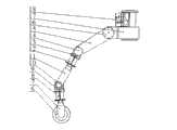
图2是轮足式运动支链三维示意图。Fig. 2 is a three-dimensional schematic diagram of a wheel-foot type kinematic branch chain.
图3是关节剖视图。Fig. 3 is a sectional view of the joint.
图1:1、轮足式运动支链,2、摄像头,3、电池单元,4、控制系统,5、运载平台;Figure 1: 1. Wheel-foot sports chain, 2. Camera, 3. Battery unit, 4. Control system, 5. Carrying platform;
图2:6、动力轮,7、动力轮支架,8、横滚关节,9、俯仰关节支架,10、俯仰关节,11、小腿,12、横滚关节,13、俯仰关节支架,14、俯仰关节,15、大腿,16、俯仰关节,17、偏航关节支架,18、偏航关节;Figure 2: 6. Power wheel, 7. Power wheel support, 8. Roll joint, 9. Pitch joint support, 10. Pitch joint, 11. Lower leg, 12. Roll joint, 13. Pitch joint support, 14. Pitch Joint, 15, thigh, 16, pitch joint, 17, yaw joint support, 18, yaw joint;
图3:19、关节外壳,20、左端输出轴承,21、左端盖,22、绝对编码器固定套筒,23、绝对编码器,24、输出法兰,25、波发生器椭圆塞,26、波发生器轴承,27、柔轮,28、钢轮,29、固定架,30、键,31、输入法兰,32、行星轮变速器,33、套筒,34、直流伺服电机,35、制动器,36、增量编码器,37、增量编码器固定套筒,38、右端输出轴承,39、右端盖。Figure 3: 19. Joint shell, 20. Left end output bearing, 21. Left end cover, 22. Absolute encoder fixing sleeve, 23. Absolute encoder, 24. Output flange, 25. Wave generator oval plug, 26, Wave generator bearing, 27, flexible wheel, 28, steel wheel, 29, fixed frame, 30, key, 31, input flange, 32, planetary gear transmission, 33, sleeve, 34, DC servo motor, 35, brake , 36, incremental encoder, 37, incremental encoder fixed sleeve, 38, right end output bearing, 39, right end cover.
具体实施方式Detailed ways
下面结合附图对本实用新型做进一步说明。Below in conjunction with accompanying drawing, the utility model is further described.
参照图1~图3,一种三轮足式串并混联机器人,由运载平台5、摄像头2、控制单元4、电池单元3、以及3条结构完全一样的轮足式运动支链1组成。Referring to Figures 1 to 3, a three-wheel-footed series-parallel hybrid robot is composed of a carrying
由图2可见所述的每一个运动支链由偏航关节18、偏航关节支架17、上俯仰关节16,中俯仰关节14,下俯仰关节10、中俯仰关节支架13、中俯仰关节支架9、上横滚关节12,下横滚关节8、大腿15、小腿11、动力轮6、动力轮支架7构成。It can be seen from Fig. 2 that each motion branch chain described is composed of yaw joint 18, yaw joint support 17, upper pitch joint 16, middle pitch joint 14, lower pitch joint 10, middle pitch
偏航关节18的端盖通过螺钉与运载平台5固接在一起,无相对转动,而同时偏航关节18的关节外壳通过螺钉与偏航关节支架17连接并带动偏航关节支架17转动,偏航关节支架17通过螺钉与上俯仰关节16的端盖固接,无相对转动,上俯仰关节16的关节外壳通过螺钉与大腿15连接并带动大腿15转动,大腿15通过螺钉与中俯仰关节14的端盖固接,无相对转动,中俯仰关节14的关节外壳通过螺钉与中俯仰关节支架13连接并带动俯仰关节支架13转动,中仰关节支架13通过螺钉与上横滚关节12的端盖固接,无相对转动,上横滚关节12的关节外壳通过螺钉与小腿11连接并带动小腿11转动,小腿11通过螺钉与下俯仰关节10的端盖固接,无相对转动,下俯仰关节10的关节外壳通过螺钉与下俯仰关节支架9连接并带动俯仰关节支架9转动,下仰关节支架9通过螺钉与下横滚关节8的端盖固接,无相对转动,下横滚关节8的关节外壳通过螺钉与动力轮支架7连接并带动动力轮支架7转动,动力轮支架7与动力轮6连接。The end cover of the yaw joint 18 is fixedly connected with the carrying
如图3所示,所述的关节由关节外壳19、左端输出轴承20、左端盖21、绝对编码器固定套筒22、绝对编码器23、输出法兰24、波发生器椭圆塞25、波发生器轴承26、柔轮27、钢轮28、固定架29、键30、输入法兰31、行星轮变速器32、套筒33、直流伺服电机34、制动器35、增量编码器36、增量编码器固定套筒37、右端输出轴承38、右端盖39组成。As shown in Figure 3, the joint is composed of
绝对编码器23通过绝对编码器固定套筒22定位于左端盖21,关节外壳19通过左端输出轴承20与绝对编码器底座21可转动连接,关节外壳19通过螺钉与固定架29固接,固定架29通过螺栓固接谐波减速器的钢轮28,所述谐波减速器的钢轮28与谐波减速器的柔轮27啮合,谐波减速器的柔轮27通过螺栓与输入法兰31固接在一起,输出法兰24与波发生器椭圆塞25用螺钉相接,而行星轮变速器32的输出轴通过键与输出法兰24连接,套筒33通过螺栓分别与输入法兰31和右端盖39固定连接,所述行星轮变速器32、直流伺服电机34、制动器35和增量编码器36位于套筒33内,制动器35与增量编码器36连接,直流伺服电机34输出轴一端与制动器35连接,另一端与行星轮变速器32连接,关节外壳19与右端盖34通过右端输出轴承38转动连接,增量编码器36通过增量编码器固定套筒37定位并固定在右端盖39内。The absolute encoder 23 is positioned on the left end cover 21 through the absolute encoder fixing sleeve 22, the joint housing 19 is rotatably connected to the absolute encoder base 21 through the left end output bearing 20, the joint housing 19 is fixed to the fixing frame 29 through screws, and the fixing frame 29 is fixed to the steel wheel 28 of the harmonic reducer through bolts, the steel wheel 28 of the harmonic reducer meshes with the flexible wheel 27 of the harmonic reducer, and the flexible wheel 27 of the harmonic reducer is connected to the input flange 31 through bolts Fixed together, the output flange 24 is connected with the wave generator elliptical plug 25 with screws, and the output shaft of the planetary gear transmission 32 is connected with the output flange 24 through a key, and the sleeve 33 is respectively connected with the input flange 31 and the The right end cover 39 is fixedly connected, and the planetary gear transmission 32, the DC servo motor 34, the brake 35 and the incremental encoder 36 are located in the sleeve 33, the brake 35 is connected with the incremental encoder 36, and one end of the output shaft of the DC servo motor 34 is connected to the The brake 35 is connected, the other end is connected with the planetary gear transmission 32, the joint housing 19 and the right end cover 34 are rotationally connected through the right end output bearing 38, and the incremental encoder 36 is positioned and fixed in the right end cover 39 through the incremental encoder fixing sleeve 37 .
本实用新型所说的三轮足式串并混联机器人的工作原理是通过控制三条运动支链中直流伺服电机34的转动来控制运动支链中小腿与大腿的转动以及控制动力轮的锁定与转动,从而实现运载平台5的2种运动,即步行运动及滚动前进。The working principle of the said three-wheel foot type series-parallel hybrid robot in the utility model is to control the rotation of the calf and the thigh in the motion branch chain and the locking and locking of the control power wheel by controlling the rotation of the
而各个关节的工作原理是行星轮变速器32通过输出法兰24和键30驱动波发生器椭圆塞25,波发生器椭圆塞25通过波发生器轴承26以及柔轮27进一步驱动钢轮28,关节外壳19通过固定架29与钢轮28固接,从而将钢轮28的转动传递到关节外壳19。本关节中,柔轮27与输入法兰31、行星轮变速器32、套筒33、直流伺服电机34、制动器35、增量编码器36、增量编码器固定套筒37、右端盖39固联在一起,它们之间没有相对转动,故关节外壳19通过左端输出轴承20及右端输出轴承38与左端盖21和右端盖39可转动连接,及它们之间存在相对转动。因此当直流伺服电机34转动时,关节外壳19与左端盖21和右端盖39之间就有经谐波减速器减速后的相对转动,关节外壳19就可带动固接在其上的大腿15及小腿11转动。The working principle of each joint is that the
本实用新型的三轮足式串并混联机器人由3个6自由度的轮足组合式运动支链、运载平台、电池、控制系统、摄像头等组成,如图1所示。每个运动支链都完全相同,且可以成为独立的串联机械臂,如图2所示。每个轮足式运动支链含有偏航、俯仰、俯仰、横滚、俯仰、横滚关节,俯仰、偏航支架及动力轮和动力轮支架。机器人运载平台设计成正三角形,每个运动支链通过偏航关节安装在运载平台正三角形顶点位置。运动支链末端是动力轮。所述每一个运动支链中,上俯仰关节通过偏航关节与运载平台可转动连接,大腿与上俯仰关节为转动连接,又与中俯仰关节为转动连接,上横滚关节可绕中俯仰关节转动,小腿与下俯仰关节和上横滚关节为转动连接,下横滚关节可绕下俯仰关节转动,动力轮可绕下横滚关节转动。The three-wheel-foot type series-parallel hybrid robot of the utility model is composed of three 6-degree-of-freedom wheel-foot combined motion branch chains, a carrying platform, a battery, a control system, a camera, etc., as shown in Figure 1. Each kinematic branch is identical and can become an independent serial manipulator, as shown in Figure 2. Each wheel-foot motion branch chain contains yaw, pitch, pitch, roll, pitch, roll joints, pitch, yaw brackets and power wheels and power wheel brackets. The robot carrying platform is designed as an equilateral triangle, and each motion branch chain is installed at the apex of the carrying platform through the yaw joint. The end of the kinematic branch is the power wheel. In each of the motion branch chains, the upper pitch joint is rotatably connected to the carrier platform through the yaw joint, the thigh is rotationally connected to the upper pitch joint, and is also rotationally connected to the middle pitch joint, and the upper roll joint can rotate around the middle pitch joint For rotation, the lower leg is rotationally connected with the lower pitch joint and the upper roll joint, the lower roll joint can rotate around the lower pitch joint, and the power wheel can rotate around the lower roll joint.
上述运动支链中小腿绕俯仰关节可转动直至折叠进大腿里,而大腿可绕俯仰关节转动折叠到运载平台三角形内,且其沿着运载平台三角形各边方向排列,从而使得整条运动支链都收缩至运载平台三角形范围之内。The calf in the above motion branch chain can rotate around the pitch joint until it is folded into the thigh, and the thigh can rotate around the pitch joint and fold into the triangle of the carrying platform, and they are arranged along the sides of the triangle of the carrying platform, so that the entire motion branch chain They are all shrunk to within the triangle range of the carrying platform.
所述的关节中,如图3所示,绝对编码器通过绝对编码器固定套筒定位于绝对编码器底座,关节外壳通过左端输出轴承与绝对编码器底座可转动连接,同时通过螺钉与固定架固接,固定架通过螺栓固接谐波减速器的钢轮,谐波减速器的柔轮通过螺栓与输入法兰固接在一起,输出法兰与波发生器椭圆塞用螺钉相接,而行星轮变速器的输出轴通过键与输出法兰连接,套筒通过螺栓分别与输入法兰和增量编码器底座固定连接,所述行星轮变速器、直流伺服电机、制动器和增量编码器位于套筒内,制动器与增量编码器连接,直流伺服电机输出轴一端与制动器连接,另一端与行星轮变速器连接,节外壳与增量编码器底座通过右端输出轴承转动连接,增量编码器通过增量编码器固定套筒定位并固定在增量编码器底座内。In the above-mentioned joint, as shown in Figure 3, the absolute encoder is positioned on the absolute encoder base through the absolute encoder fixing sleeve, and the joint shell is rotatably connected to the absolute encoder base through the left end output bearing, and at the same time, the screw is connected to the fixing frame Fixed connection, the fixed frame is fixed to the steel wheel of the harmonic reducer through bolts, the flexible wheel of the harmonic reducer is fixed to the input flange through bolts, the output flange is connected to the elliptical plug of the wave generator with screws, and The output shaft of the planetary gear transmission is connected to the output flange through a key, and the sleeve is fixedly connected to the input flange and the base of the incremental encoder through bolts. The planetary gear transmission, DC servo motor, brake and incremental encoder are located on the sleeve. In the barrel, the brake is connected to the incremental encoder, one end of the output shaft of the DC servo motor is connected to the brake, and the other end is connected to the planetary gear transmission. The fixed sleeve of the incremental encoder is positioned and fixed in the base of the incremental encoder.
上述的关节中的谐波减速器的钢轮通过螺栓与固定架固接在一起,而关节外壳又通过螺钉与固定架固接,所以当钢轮转动时可带动关节外壳一起转动。谐波减速器的波发生器去除了联轴器,直接靠输出法兰通过螺钉连接带动波发生器椭圆塞转动,这样设计可节省成本并减轻关节重量。The steel wheel of the harmonic reducer in the above-mentioned joint is fixed together with the fixed frame through bolts, and the joint shell is fixed with the fixed frame through screws, so when the steel wheel rotates, it can drive the joint shell to rotate together. The wave generator of the harmonic reducer eliminates the coupling, and directly relies on the output flange to drive the elliptical plug of the wave generator to rotate through screw connection. This design can save costs and reduce joint weight.
Claims (3)
Priority Applications (1)
| Application Number | Priority Date | Filing Date | Title |
|---|---|---|---|
| CN 201220133929CN202593676U (en) | 2012-03-31 | 2012-03-31 | Three-wheel-foot type serial-parallel combined robot |
Applications Claiming Priority (1)
| Application Number | Priority Date | Filing Date | Title |
|---|---|---|---|
| CN 201220133929CN202593676U (en) | 2012-03-31 | 2012-03-31 | Three-wheel-foot type serial-parallel combined robot |
Publications (1)
| Publication Number | Publication Date |
|---|---|
| CN202593676Utrue CN202593676U (en) | 2012-12-12 |
Family
ID=47311247
Family Applications (1)
| Application Number | Title | Priority Date | Filing Date |
|---|---|---|---|
| CN 201220133929Expired - LifetimeCN202593676U (en) | 2012-03-31 | 2012-03-31 | Three-wheel-foot type serial-parallel combined robot |
Country Status (1)
| Country | Link |
|---|---|
| CN (1) | CN202593676U (en) |
Cited By (8)
| Publication number | Priority date | Publication date | Assignee | Title |
|---|---|---|---|---|
| CN102849141A (en)* | 2012-03-31 | 2013-01-02 | 浙江工业大学 | Three-wheel walking robot of series and parallel connection |
| CN103558565A (en)* | 2013-10-14 | 2014-02-05 | 中国科学院电工研究所 | Three-leg type magnetic field detection robot |
| CN103612685A (en)* | 2013-11-29 | 2014-03-05 | 哈尔滨工程大学 | Leg type rotatable quadruped robot with crawler wheels and driving wheels |
| CN103661663A (en)* | 2013-12-05 | 2014-03-26 | 上海工程技术大学 | Novel ground condition adaptation type bouncing power leg of hopping robot |
| CN104859744A (en)* | 2015-05-12 | 2015-08-26 | 上海大学 | Driven wheel type swing arm omnidirectional sliding robot |
| CN105774940A (en)* | 2016-04-01 | 2016-07-20 | 北京交通大学 | Tripodal multidirectional mobile robot |
| CN109176459A (en)* | 2018-10-26 | 2019-01-11 | 清华大学 | Multi-functional absorption type mobile platform |
| CN111872916A (en)* | 2020-07-22 | 2020-11-03 | 燕山大学 | Posture-adjustable three-degree-of-freedom parallel rescue robot |
- 2012
- 2012-03-31CNCN 201220133929patent/CN202593676U/ennot_activeExpired - Lifetime
Cited By (14)
| Publication number | Priority date | Publication date | Assignee | Title |
|---|---|---|---|---|
| CN102849141A (en)* | 2012-03-31 | 2013-01-02 | 浙江工业大学 | Three-wheel walking robot of series and parallel connection |
| CN102849141B (en)* | 2012-03-31 | 2014-11-12 | 浙江工业大学 | Three-wheel walking robot of series and parallel connection |
| CN103558565B (en)* | 2013-10-14 | 2016-06-01 | 中国科学院电工研究所 | A kind of Three-leg type magnetic field detection robot |
| CN103558565A (en)* | 2013-10-14 | 2014-02-05 | 中国科学院电工研究所 | Three-leg type magnetic field detection robot |
| CN103612685A (en)* | 2013-11-29 | 2014-03-05 | 哈尔滨工程大学 | Leg type rotatable quadruped robot with crawler wheels and driving wheels |
| CN103612685B (en)* | 2013-11-29 | 2017-02-08 | 哈尔滨工程大学 | Leg type rotatable quadruped robot with crawler wheels and driving wheels |
| CN103661663A (en)* | 2013-12-05 | 2014-03-26 | 上海工程技术大学 | Novel ground condition adaptation type bouncing power leg of hopping robot |
| CN104859744A (en)* | 2015-05-12 | 2015-08-26 | 上海大学 | Driven wheel type swing arm omnidirectional sliding robot |
| CN105774940A (en)* | 2016-04-01 | 2016-07-20 | 北京交通大学 | Tripodal multidirectional mobile robot |
| CN105774940B (en)* | 2016-04-01 | 2018-01-12 | 北京交通大学 | Tripodia Multidirectional-moving robot |
| CN109176459A (en)* | 2018-10-26 | 2019-01-11 | 清华大学 | Multi-functional absorption type mobile platform |
| CN109176459B (en)* | 2018-10-26 | 2021-08-10 | 清华大学 | Multifunctional adsorption type mobile platform |
| CN111872916A (en)* | 2020-07-22 | 2020-11-03 | 燕山大学 | Posture-adjustable three-degree-of-freedom parallel rescue robot |
| CN111872916B (en)* | 2020-07-22 | 2021-12-21 | 燕山大学 | A three-degree-of-freedom parallel rescue robot with adjustable posture |
Similar Documents
| Publication | Publication Date | Title |
|---|---|---|
| CN102616296B (en) | A six-wheeled serial-parallel hybrid robot | |
| CN202593676U (en) | Three-wheel-foot type serial-parallel combined robot | |
| CN202593677U (en) | Six-wheel-foot type series-parallel mixed combination robot | |
| CN102849141B (en) | Three-wheel walking robot of series and parallel connection | |
| CN103287523B (en) | The composite deformation mobile robot that a kind of elastic foot is combined with wheel type motion mechanism | |
| CN104369790B (en) | A kind of biped robot's walking mechanism | |
| CN105172933B (en) | A spider-like multi-legged robot platform | |
| CN111360868A (en) | Limb structure of a bionic robot with parallel drive joints and a bionic robot | |
| CN103395456B (en) | Complicated landform movable robot with wheel legs | |
| CN110293543A (en) | A kind of multistep state snake-shaped robot merging crawler type walking mechanism and snake neck joint | |
| CN106828655A (en) | With multivariant climbing robot | |
| CN101850797B (en) | Modularized multiped walking robot capable of realizing functional shift between hands and feet | |
| CN201120914Y (en) | Six-wheel/leg hemispherical shell detection robot | |
| CN201712689U (en) | Modular six-degree-of-freedom active joint type biped walking robot | |
| CN101125564A (en) | Six-wheel/leg hemispherical shell detection robot | |
| CN103538644A (en) | Robot with functions of rolling motion and foot walking | |
| CN205059786U (en) | Polypody robot platform with visual system | |
| CN202243746U (en) | Self-adaptive crawler-arm compound driven biomimetic robot suitable for various road conditions | |
| CN101423075A (en) | Modular six freedom-degree initiative joint type bipod walking robot | |
| CN108748124A (en) | Snake-shaped robot | |
| CN101423074A (en) | Modular double-wheel driven mobile robot capable of the changing wheel span and wheel direction | |
| CN201120913Y (en) | A quadruped crawling robot | |
| CN1644328A (en) | Small crawler leg composite movable robot mechanism | |
| CN104709369A (en) | Planetary differential obstacle-crossing type tracked robot | |
| CN203946188U (en) | A kind of cross joint module for walking robot |
Legal Events
| Date | Code | Title | Description |
|---|---|---|---|
| C14 | Grant of patent or utility model | ||
| GR01 | Patent grant | ||
| AV01 | Patent right actively abandoned | Granted publication date:20121212 Effective date of abandoning:20141112 | |
| AV01 | Patent right actively abandoned | Granted publication date:20121212 Effective date of abandoning:20141112 | |
| RGAV | Abandon patent right to avoid regrant |