CN202550251U - Joint for connecting detection device and detection point - Google Patents
Joint for connecting detection device and detection pointDownload PDFInfo
- Publication number
- CN202550251U CN202550251UCN2012200544628UCN201220054462UCN202550251UCN 202550251 UCN202550251 UCN 202550251UCN 2012200544628 UCN2012200544628 UCN 2012200544628UCN 201220054462 UCN201220054462 UCN 201220054462UCN 202550251 UCN202550251 UCN 202550251U
- Authority
- CN
- China
- Prior art keywords
- connector
- contact
- main
- detection device
- bypass
- Prior art date
- Legal status (The legal status is an assumption and is not a legal conclusion. Google has not performed a legal analysis and makes no representation as to the accuracy of the status listed.)
- Expired - Fee Related
Links
Images


Landscapes
- Testing Of Short-Circuits, Discontinuities, Leakage, Or Incorrect Line Connections (AREA)
Abstract
Translated fromChinese
Description
Translated fromChinese技术领域technical field
本实用新型涉及用于电气检测过程中的附件,尤其是一种用于连接检测装置与检测点的接头。The utility model relates to an accessory used in the electrical detection process, in particular to a joint used for connecting a detection device and a detection point.
背景技术Background technique
在进行电气检测的过程中,有时候需要依次将不同检测点的多个信号传输至同一检测装置进行检测,目前检测点与检测装置之间的连接大都是靠电连接器实现的,然而不同检测点处使用的电连接器的型号、大小往往不同,这就需要同时准备多个电连接器,所述电连接器包括筒形的壳体及通过绝缘体装配于所述壳体内的接触件,所述接触件上连接有用于与检测装置连接的扩展线缆,在针对不同的检测点进行检测时,通过更换电连接器的形式来实现不同检测点与检测装置之间的连接,这一方面大大增加了工作人员携带的电连接器的数量,容易造成不同电连接器之间的混淆,另一方面也降低了工作人员的工作效率。In the process of electrical detection, sometimes it is necessary to sequentially transmit multiple signals from different detection points to the same detection device for detection. At present, the connection between the detection point and the detection device is mostly realized by electrical connectors. However, different detection The type and size of the electrical connectors used at the points are often different, which requires preparing multiple electrical connectors at the same time. The electrical connectors include a cylindrical shell and a contact piece assembled in the shell through an insulator. The contact piece is connected with an extension cable for connection with the detection device. When detecting different detection points, the connection between different detection points and the detection device is realized by replacing the form of the electrical connector. The increase in the number of electrical connectors carried by the staff may easily cause confusion among different electrical connectors, and on the other hand, the work efficiency of the staff is also reduced.
发明内容Contents of the invention
本实用新型的目的在于提供一种用于连接检测装置与检测点的接头,以解决检测装置在对不同的检测点进行检测时需整体更换检测装置与检测点之间的连接部件的问题。The purpose of the utility model is to provide a joint for connecting a detection device and a detection point to solve the problem that the detection device needs to replace the connecting parts between the detection device and the detection point when it detects different detection points.
为了解决上述问题,本实用新型的用于连接检测装置与检测点的接头采用以下技术方案:用于连接检测装置与检测点的接头,包括连接器基体,连接器基体包括呈空心筒形的安装座,所述安装座分别于两端固定装配有第一、第二连接器,于周向上装配有第三连接器,所述第一、第二、第三连接器的壳体均与安装座的内腔相通,第一、第二、第三连接器具有对应的接触件且对应的接触件均通过安装座内的线缆电性连接,所述第一、第二、第三连接器中的一个为用于与检测装置插接的输出连接器,输出连接器具有扩展接触件,所述扩展接触件通过扩展线缆连接有一个以上外接连接器,所述外接电连接器的接触件与所述扩展接触件对应电性连接。In order to solve the above problems, the joint used to connect the detection device and the detection point of the utility model adopts the following technical scheme: the joint used to connect the detection device and the detection point includes a connector base, and the connector base includes a hollow cylindrical installation seat, the mounting seat is respectively fixedly equipped with first and second connectors at both ends, and is equipped with a third connector in the circumferential direction, and the shells of the first, second and third connectors are connected with the mounting seat The first, second, and third connectors have corresponding contacts and the corresponding contacts are all electrically connected through the cables in the mounting base. The first, second, and third connectors One of them is an output connector for plugging with the detection device. The output connector has an extended contact piece, and the extended contact piece is connected to more than one external connector through an extension cable. The contact piece of the external electrical connector is connected to the The extended contacts correspond to electrical connections.
所述外接连接器有两个且分为主连接器及旁路连接器,主连接器包括主壳体,旁路连接器包括旁路壳体,所述旁路壳体的一端固定装配于主壳体的周向上并与主壳体连通,另一端向主壳体的径向外围悬伸,主连接器的接触件为主接触件,所述扩展线缆从主壳体的后端进入主壳体并与所述主接触件对应连接,旁路连接器的接触件为旁路接触件,所述旁路接触件与主接触件一一对应电性连接并通过主接触件与对应的扩展接触件电性连接。There are two external connectors and they are divided into a main connector and a bypass connector. The main connector includes a main housing, and the bypass connector includes a bypass housing. The circumferential direction of the housing is connected with the main housing, and the other end is suspended to the radial periphery of the main housing. The contact of the main connector is the main contact, and the extension cable enters the main housing from the rear end of the main housing. The housing is correspondingly connected with the main contact, and the contact of the bypass connector is a bypass contact, and the bypass contact is electrically connected with the main contact one by one and is connected to the corresponding extension The contacts are electrically connected.
所述第三连接器为输出连接器。The third connector is an output connector.
所述主接触件及旁路接触件中的一个为插孔接触件,另一个为插针接触件。One of the main contact and the bypass contact is a socket contact, and the other is a pin contact.
所述第一连接器的接触件为插孔接触件,第二、第三连接器的接触件均为插针接触件。The contacts of the first connector are socket contacts, and the contacts of the second and third connectors are pin contacts.
由于本实用新型的用于连接检测装置与检测点的接头在同一安装座上设有所述第一、第二、第三连接器,且第一、第二、第三连接器之间具有对应电性连接的接触件,因此在使用时,可通过第一、第二、第三连接器中的一个与对应的检测装置插接,视情况通过另外两个与对应的检测点插接,在不同的两检测点之间切换时,只需通过调换与检测点插接的连接器即可;另外,由于所述外接连接器的存在,可根据需要适当的扩展连接器的插接部分的个数,从而适用于对更多检测点的检测,在对不同检测点进行检测时不必从检测装置处将电连接器整体取下更换,解决了检测装置在对不同的检测点进行检测时需整体更换检测装置与检测点之间的连接部件的问题。Since the joint used to connect the detection device and the detection point of the utility model is provided with the first, second, and third connectors on the same mounting base, and the first, second, and third connectors have corresponding Electrically connected contacts, so when in use, one of the first, second, and third connectors can be plugged into the corresponding detection device, and the other two can be plugged into the corresponding detection point as the case may be. When switching between two different detection points, it is only necessary to exchange the connector plugged into the detection point; in addition, due to the existence of the external connector, the individuality of the plug-in part of the connector can be appropriately expanded as required. number, so it is suitable for the detection of more detection points. When detecting different detection points, it is not necessary to remove and replace the electrical connector from the detection device as a whole, which solves the problem that the detection device needs to be integrated when detecting different detection points. The problem of replacing the connecting parts between the detection device and the detection point.
附图说明Description of drawings
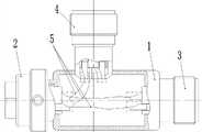
图1是本实用新型的用于连接检测装置与检测点的接头的实施例1的结构示意图;Fig. 1 is a schematic structural view of
图2是图1中的连接器基体的结构示意图;Fig. 2 is a schematic structural view of the connector base in Fig. 1;
图3是图2的左视图;Fig. 3 is the left view of Fig. 2;
图4是图2的俯视图;Fig. 4 is the top view of Fig. 2;
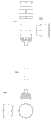
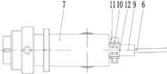
图5是图1中的外接连接器的结构示意图;Fig. 5 is a schematic structural diagram of the external connector in Fig. 1;
图6是图5的仰视图;Fig. 6 is the bottom view of Fig. 5;
图7是图5的俯视图。FIG. 7 is a top view of FIG. 5 .
具体实施方式Detailed ways
本实用新型的用于连接检测装置与检测点的接头的实施例1,如图1-7所示,由连接器基体及外接连接器构成。连接器基体由安装座1及装配于安装座1上的第一连接器2、第二连接器3及第三连接器4组成。安装座1呈两端开口的筒形,第一、第二连接器分别同轴固定装配于安装座1的两端,第三连接器4固定装配于安装座1的周向上且其轴线沿安装座1的径向延伸;第一、第二、第三连接器均通过各自的壳体与安装座1固定配合且它们的壳体与安装座1固定配合的一端均与安装座1的内腔相通,第一连接器2有三个接触件,第一连接器2的接触件为插孔接触件,此处设第一连接器2的接触件分别为a、b、c,第二连接器3同样有三个接触件,三个接触件均为插针接触件,此处设该三个接触件为A、B、C,第三连接器4为用于与对应的检测装置插接的输出连接器,第三连接器4具有六个接触件,六个接触件均为插针接触件,此处设该六个接触件为d、e、f、g、h、i,其中接触件a、A、d互相对应并通过安装座内的线缆5电性连接,接触件b、B、e互相对应并通过安装座内的线缆5电性连接,接触件c、C、f互相对应并通过安装座内的线缆5电性连接,从而可通过第一、第二、第三连接器中的一个来(不同时)检测另外两个上的信号,接触件g、h、i为扩展接触件且连接有扩展线缆6,扩展接触件及扩展线缆6用于实现对该三通连接器的扩展,当三个连接器不能满足检测时的需要时,可通过所述扩展线缆外接入新的外接连接器,从而实现第三连接器对外接电连接器上的信号的检测;本实施例中,通过外接线缆接入的外接连接器有两个,两外接连接器分别为主连接器和旁路连接器。主连接器包括圆筒形的主壳体7及通过绝缘体固定装配于主壳体7内的主接触件8,主接触件8有三个,三个主接触件8均为插孔接触件,此处设该三个主接触件分别设为o、p、q,三个主接触件的接线端分别通过扩展线缆6与接触件g、h、i对应电性连接,扩展线缆6从主壳体7的后端引入并于主壳体7的后端处被压线套9、压板10及螺栓11压紧,具体地说,主壳体7的尾端处设有两个向后延伸的耳片12,螺栓11有两个且分别穿设于两耳片12上,两螺栓11之间互相平行,压板10有两个且两压板10沿对应螺栓的轴向设于耳片的两侧,压线套9插设于主壳体尾端,扩展线缆6穿过压线套9后进入主壳体7,在经过压线套时其外皮被螺栓及压板压紧,从而实现了扩展线缆6与主连接器之间的抗拉功能;旁路连接器包括圆筒形的旁路壳体13及通过绝缘体设于旁路壳体13内的旁路接触件14,旁路壳体13的一端固定装配于主壳体7的周向上并与主壳体7连通,另一端沿主壳体7的径向向外悬伸,旁路接触件14有三个,三个旁路接触件均为插针接触件,此处将三个旁路接触件分别设为O、P、Q,则主接触件o与旁路接触件O、主接触件p与旁路接触件P、主接触件q与旁路接触件Q的接线端分别通过主壳体内的线缆对应电性连接。
在本实用新型的用于连接检测装置与检测点的接头的其它实施例中,上述用于连接检测装置与检测点的接头的实施例1中所述的第一连接器的接触件还可以是插针,第二、第三连接器的接触件还可以是插孔接触件;所述扩展接触件还可以设于第一连接器或第二连接器上;所述外接连接器还可以为其它的市售电连接器。In other embodiments of the joint for connecting the detection device and the detection point of the present invention, the contact piece of the first connector described in
Claims (5)
Translated fromChinesePriority Applications (1)
| Application Number | Priority Date | Filing Date | Title |
|---|---|---|---|
| CN2012200544628UCN202550251U (en) | 2012-02-20 | 2012-02-20 | Joint for connecting detection device and detection point |
Applications Claiming Priority (1)
| Application Number | Priority Date | Filing Date | Title |
|---|---|---|---|
| CN2012200544628UCN202550251U (en) | 2012-02-20 | 2012-02-20 | Joint for connecting detection device and detection point |
Publications (1)
| Publication Number | Publication Date |
|---|---|
| CN202550251Utrue CN202550251U (en) | 2012-11-21 |
Family
ID=47170822
Family Applications (1)
| Application Number | Title | Priority Date | Filing Date |
|---|---|---|---|
| CN2012200544628UExpired - Fee RelatedCN202550251U (en) | 2012-02-20 | 2012-02-20 | Joint for connecting detection device and detection point |
Country Status (1)
| Country | Link |
|---|---|
| CN (1) | CN202550251U (en) |
Cited By (1)
| Publication number | Priority date | Publication date | Assignee | Title |
|---|---|---|---|---|
| CN104682145A (en)* | 2013-11-29 | 2015-06-03 | 上海原动力通信科技有限公司 | Coaxial adapter connector and test device for L-SMP socket |
- 2012
- 2012-02-20CNCN2012200544628Upatent/CN202550251U/ennot_activeExpired - Fee Related
Cited By (2)
| Publication number | Priority date | Publication date | Assignee | Title |
|---|---|---|---|---|
| CN104682145A (en)* | 2013-11-29 | 2015-06-03 | 上海原动力通信科技有限公司 | Coaxial adapter connector and test device for L-SMP socket |
| CN104682145B (en)* | 2013-11-29 | 2018-02-02 | 上海原动力通信科技有限公司 | Coaxial adaptor connector and L SMP socket test devices |
Similar Documents
| Publication | Publication Date | Title |
|---|---|---|
| CA2707386A1 (en) | Modular power distribution assembly with multiple circuits | |
| CN106253014A (en) | Batteries of electric automobile bag equilibrium adapter | |
| CN106099591A (en) | A kind of multifunction electronic product mix structure | |
| CN103904454A (en) | Scale type elastic reed insertion hole | |
| CN206195721U (en) | Photovoltaic connector testing arrangement | |
| CN202550251U (en) | Joint for connecting detection device and detection point | |
| CN203660163U (en) | Pole-mounted switch controller open circuit-prevention circular connector | |
| CN202797378U (en) | Plug self-conduction round connector | |
| CN202855926U (en) | Intelligent antenna bundling joint | |
| CN207572589U (en) | A kind of connector, 4-pin | |
| CN203951002U (en) | Short circuit electric connector and electric coupler component | |
| CN206990635U (en) | A kind of charger measurement jig | |
| CN110277676A (en) | Charger adapter | |
| CN202256574U (en) | Fuse ON/OFF LED light display device | |
| CN202534910U (en) | Bypass type electric connector for detection | |
| CN202534906U (en) | Electric connector used for connecting detection device with detection points | |
| CN204189980U (en) | Double-row hole connection adapter | |
| CN104966930B (en) | Heavy-load connector module | |
| CN202601889U (en) | A USB2.0 connector socket and a plug used in conjunction with it | |
| CN204205247U (en) | A kind of based on plug and the direct-connected miniaturized test adapter of printed board | |
| CN206685664U (en) | A kind of data wire of replaceable joint | |
| CN204633031U (en) | Plug-resistant electrical interface | |
| CN211404911U (en) | High-voltage interlocking loop system, female connector and male connector for high-voltage interlocking loop system | |
| CN104518319A (en) | Plug connectors, socket connectors and connector combinations | |
| CN204789654U (en) | A lead wire for switching characteristic tester |
Legal Events
| Date | Code | Title | Description |
|---|---|---|---|
| C14 | Grant of patent or utility model | ||
| GR01 | Patent grant | ||
| C17 | Cessation of patent right | ||
| CF01 | Termination of patent right due to non-payment of annual fee | Granted publication date:20121121 Termination date:20140220 |