CN202503516U - Transmission system supporting multiple communication modes - Google Patents
Transmission system supporting multiple communication modesDownload PDFInfo
- Publication number
- CN202503516U CN202503516UCN2012200853373UCN201220085337UCN202503516UCN 202503516 UCN202503516 UCN 202503516UCN 2012200853373 UCN2012200853373 UCN 2012200853373UCN 201220085337 UCN201220085337 UCN 201220085337UCN 202503516 UCN202503516 UCN 202503516U
- Authority
- CN
- China
- Prior art keywords
- module
- optical
- key light
- multiplexer
- end machine
- Prior art date
- Legal status (The legal status is an assumption and is not a legal conclusion. Google has not performed a legal analysis and makes no representation as to the accuracy of the status listed.)
- Expired - Lifetime
Links
- 230000005540biological transmissionEffects0.000titleclaimsabstractdescription19
- 238000004891communicationMethods0.000titleclaimsabstractdescription19
- 230000003287optical effectEffects0.000claimsabstractdescription70
- 230000003321amplificationEffects0.000claimsabstractdescription8
- 238000003199nucleic acid amplification methodMethods0.000claimsabstractdescription8
- 238000012544monitoring processMethods0.000claimsdescription14
- 239000013307optical fiberSubstances0.000claimsdescription10
- 230000010354integrationEffects0.000abstractdescription4
- 238000005516engineering processMethods0.000description3
- 238000012546transferMethods0.000description3
- 238000011161developmentMethods0.000description2
- 238000001914filtrationMethods0.000description2
- 238000010295mobile communicationMethods0.000description2
- 230000006855networkingEffects0.000description2
- 230000007704transitionEffects0.000description2
- 230000009286beneficial effectEffects0.000description1
- 238000006243chemical reactionMethods0.000description1
- 230000002950deficientEffects0.000description1
- 230000000694effectsEffects0.000description1
- 239000000835fiberSubstances0.000description1
- 238000000034methodMethods0.000description1
- 230000008054signal transmissionEffects0.000description1
- 239000002699waste materialSubstances0.000description1
Images

Landscapes
- Optical Communication System (AREA)
Abstract
Description
Technical field
the utility model belongs to the telecommunication transmission system technical field, relates in particular to a kind of multi-communication standard transmission system.
Background technology
to digital remote system, intermediate frequency far-drawing system, are carried out the applied more and more of signal transmission and distribution from early stage mobile communication optical fiber repeater, radio frequency stretch system as intermediary's medium at moving communicating field utilization optical fiber.No matter analog optical fiber transmission technology or digital fiber transmission technology are all quite ripe in the development of moving communicating field.With respect to traditional radio frequency cable, the loss of optical cable is little, anti-interference good, cost is low, has effectively overcome the little defective of cable distribution radius.But the various Optical fiber relay system that in mobile communications network, uses at present all only supports two kinds of communication standards that a kind of communication standard or frequency are close, perhaps will support the Optical fiber relay system in combination use of two kinds of communication standards, and system resource waste, cost are higher; Under the present increasing development trend of communication standard, be difficult to satisfy the requirement that multiple communication standard inserts.
Summary of the invention
the utility model is exactly to the problems referred to above, and the multi-communication standard transmission system that a kind of integrated level is high, transmission cost is low is provided.
are for realizing above-mentioned purpose; The utility model adopts following technical scheme; The utility model comprises near-end machine, repeater and remote termination; Near-end machine, repeater, remote termination link to each other successively, and its structural feature: said near-end machine comprises first multiplexer, the first key light module, first optical branching device, and first multiplexer, the first key light module, first optical branching device link to each other successively; Said first multiplexer carries out branch, closes the road the multi-modulation scheme signal, the said first key light module to signal modulate, demodulation, compensation amplify.
said repeater comprises first from optical module, compensation amplification module, the second key light module, second optical branching device; First links to each other from optical module, compensation amplification module, the second key light module, second optical branching device successively, and first links to each other with the first key light module, first optical branching device respectively from optical module; Said first from optical module to signal modulate, demodulation.
said remote termination comprises second from optical module, multimode integrated module, second multiplexer; Second links to each other from optical module, multimode integrated module, second multiplexer successively, and second links to each other with the second key light module, second optical branching device respectively from optical module; Said multimode integrated module amplifies the uplink and downlink link radiofrequency signal of each standard.
As a kind of preferred version, the utility model said second links to each other through optical fiber with the second key light module, second optical branching device respectively from optical module.
as another kind of preferred version, the said near-end machine of the utility model also comprises first monitoring module, and first monitoring module links to each other with the first key light module; Said repeater also comprises second monitoring module, and second monitoring module links to each other from optical module, the second key light module with first respectively.
the utility model beneficial effect: the utility model carries out radio frequency with the signal of the different systems of common carrier and different frequency range at the near-end machine and closes the road, carries out light modulation then, and the signal of light modulation is carried out light along separate routes, transfers to repeater.Repeater transfers light signal to attenuation compensation that radiofrequency signal is carried out light path, carries out light modulation and light afterwards again and uses Optical Fiber Transmission to remote termination in the back along separate routes.Therefore, the utility model has been realized multi-communication standard signal common one cover transmission system, and the output of antenna opening multi-band signal has improved system integration degree, has saved resources such as transmission system, antenna feeder, feeder line.
Description of drawings
further specify the utility model below in conjunction with accompanying drawing and embodiment, and the utility model protection range not only is confined to the statement of following content.
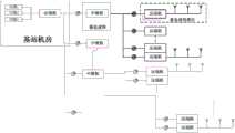
Fig. 1 is the utility model structural representation.
Fig. 2 is the utility model near-end machine structural representation.
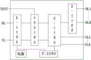
Fig. 3 is the utility model repeater structural representation.
Fig. 4 is the utility model remote termination structural representation.
Embodiment
are as shown in the figure, and the utility model comprises near-end machine, repeater and remote termination, and near-end machine, repeater, remote termination link to each other successively.
said near-end machine comprises first multiplexer, the first key light module, first optical branching device, and first multiplexer, the first key light module, first optical branching device link to each other successively; Said first multiplexer carries out branch, closes the road the multi-modulation scheme signal, the said first key light module to signal modulate, demodulation, compensation amplify.The major function of near-end machine is the multi-modulation scheme downstream signal that receives to be carried out radio frequency close the road, is modulated into light signal and transmits; The uplink optical signal that simultaneously repeater is transmitted is separated to be in harmonious proportion to compensate and is amplified, and filtering exports corresponding standard base station to.
said repeater comprises first from optical module, compensation amplification module, the second key light module, second optical branching device; First links to each other from optical module, compensation amplification module, the second key light module, second optical branching device successively, and first links to each other with the first key light module, first optical branching device respectively from optical module; Said first from optical module to signal modulate, demodulation.Repeater is realized the function of the quantity of the configurable remote termination of increase near-end machine, the conversion that communicates simultaneously as the node of network.At down link, the downlink optical signal that repeater receives optical fiber carries out carrying out after the demodulation transition of communications of FSK, and the signal of communication that amplifies demodulation simultaneously compensates; Being divided into 8 passages again transmits.In up link, 8 passage uplink optical signals that repeater will receive are separated and are in harmonious proportion the FSK transition of communications, carry out gain compensation after up radiofrequency signal is closed the road, are modulated into the single channel light signal and transmit, thereby realize increasing the function of remote termination quantity.
said remote termination comprises second from optical module, multimode integrated module, second multiplexer; Second links to each other from optical module, multimode integrated module, second multiplexer successively, and second links to each other with the second key light module, second optical branching device respectively from optical module; Said multimode integrated module amplifies the uplink and downlink link radiofrequency signal of each standard, accomplishes the collection that software supervision and complete machine to complete machine need parameter simultaneously.The branch standard was amplified to power demand after remote termination was demodulated to downlink radio-frequency signal with downlink optical signal, closed the road through second multiplexer and exported cover antenna to; Multiple standard upward signal gets into remote termination after the second multiplexer filtering, is amplified, closed by the low noise amplifier of standard separately to be modulated into light signal behind the road and to transmit.
said second link to each other through optical fiber with the second key light module, second optical branching device respectively from optical module; Being of value to signal transfer quality and coverage distance increases.
said near-end machine also comprises first monitoring module, and first monitoring module links to each other with the first key light module; Said repeater also comprises second monitoring module, and second monitoring module links to each other from optical module, the second key light module with first respectively.First monitoring module is accomplished condition monitoring, operating state indication to the near-end machine, is amplified the link gain setting, local communication, telecommunication, function such as communicate by letter with other functional unit of covering system.
the utility model can have following several kinds of networking modes to different operators.
(1) China Mobile: GSM/DCS/TD/WLAN.
(2) CHINAUNICOM: GSM/DCS/WCDMA/WLAN.
(3) China Telecom: CDMA/CDMA2000/WLAN.
(4) comprehensive full-service networking: GSM/DCS/TD/ WCDMA/ CDMA/CDMA2000/WLAN.
are the WLAN part wherein, can directly wireless aps (WAP) be put into remote termination.
it is understandable that; More than about the specific descriptions of the utility model; Only be used to the utility model is described and be not to be subject to the described technical scheme of the utility model embodiment; Those of ordinary skill in the art should be appreciated that still and can make amendment or be equal to replacement the utility model, to reach identical technique effect; As long as satisfy the use needs, all within the protection range of the utility model.
Claims (3)
1. the multi-communication standard transmission system comprises near-end machine, repeater and remote termination, and near-end machine, repeater, remote termination link to each other successively, it is characterized in that:
Said near-end machine comprises first multiplexer, the first key light module, first optical branching device, and first multiplexer, the first key light module, first optical branching device link to each other successively; Said first multiplexer carries out branch, closes the road the multi-modulation scheme signal, the said first key light module to signal modulate, demodulation, compensation amplify;
Said repeater comprises first from optical module, compensation amplification module, the second key light module, second optical branching device; First links to each other from optical module, compensation amplification module, the second key light module, second optical branching device successively, and first links to each other with the first key light module, first optical branching device respectively from optical module; Said first from optical module to signal modulate, demodulation;
Said remote termination comprises second from optical module, multimode integrated module, second multiplexer, and second links to each other from optical module, multimode integrated module, second multiplexer successively, and second links to each other with the second key light module, second optical branching device respectively from optical module; Said multimode integrated module amplifies the uplink and downlink link radiofrequency signal of each standard.
2. according to the said multi-communication standard transmission system of claim 1, it is characterized in that said second links to each other through optical fiber with the second key light module, second optical branching device respectively from optical module.
3. according to the said multi-communication standard transmission system of claim 1, it is characterized in that said near-end machine also comprises first monitoring module, first monitoring module links to each other with the first key light module; Said repeater also comprises second monitoring module, and second monitoring module links to each other from optical module, the second key light module with first respectively.
Priority Applications (1)
| Application Number | Priority Date | Filing Date | Title |
|---|---|---|---|
| CN2012200853373UCN202503516U (en) | 2012-03-09 | 2012-03-09 | Transmission system supporting multiple communication modes |
Applications Claiming Priority (1)
| Application Number | Priority Date | Filing Date | Title |
|---|---|---|---|
| CN2012200853373UCN202503516U (en) | 2012-03-09 | 2012-03-09 | Transmission system supporting multiple communication modes |
Publications (1)
| Publication Number | Publication Date |
|---|---|
| CN202503516Utrue CN202503516U (en) | 2012-10-24 |
Family
ID=47040113
Family Applications (1)
| Application Number | Title | Priority Date | Filing Date |
|---|---|---|---|
| CN2012200853373UExpired - LifetimeCN202503516U (en) | 2012-03-09 | 2012-03-09 | Transmission system supporting multiple communication modes |
Country Status (1)
| Country | Link |
|---|---|
| CN (1) | CN202503516U (en) |
Cited By (7)
| Publication number | Priority date | Publication date | Assignee | Title |
|---|---|---|---|---|
| CN105141367A (en)* | 2015-07-13 | 2015-12-09 | 广州杰赛科技股份有限公司 | Wireless communication system and method realizing multipath access of different-address information sources |
| CN105141366A (en)* | 2015-07-13 | 2015-12-09 | 广州杰赛科技股份有限公司 | Multi-service optical fiber distribution system and method |
| CN105141363A (en)* | 2015-07-13 | 2015-12-09 | 广州杰赛科技股份有限公司 | Optical fiber distribution system and method realizing multipath access of different-address information sources |
| CN105141368A (en)* | 2015-07-13 | 2015-12-09 | 广州杰赛科技股份有限公司 | Optical fiber distribution system and method supporting multi-communication-standard access |
| CN105245280A (en)* | 2015-07-13 | 2016-01-13 | 广州杰赛科技股份有限公司 | Fiber distribution system with realization of integration of multiple networks and method |
| WO2016179750A1 (en)* | 2015-05-08 | 2016-11-17 | 京信通信技术(广州)有限公司 | Method and device for controlling gain of relay in active das system, and relay machine |
| CN108833017A (en)* | 2018-07-03 | 2018-11-16 | 京信通信系统(中国)有限公司 | Single system repeater system and its signal compatibility method and device |
- 2012
- 2012-03-09CNCN2012200853373Upatent/CN202503516U/ennot_activeExpired - Lifetime
Cited By (12)
| Publication number | Priority date | Publication date | Assignee | Title |
|---|---|---|---|---|
| WO2016179750A1 (en)* | 2015-05-08 | 2016-11-17 | 京信通信技术(广州)有限公司 | Method and device for controlling gain of relay in active das system, and relay machine |
| CN105141367A (en)* | 2015-07-13 | 2015-12-09 | 广州杰赛科技股份有限公司 | Wireless communication system and method realizing multipath access of different-address information sources |
| CN105141366A (en)* | 2015-07-13 | 2015-12-09 | 广州杰赛科技股份有限公司 | Multi-service optical fiber distribution system and method |
| CN105141363A (en)* | 2015-07-13 | 2015-12-09 | 广州杰赛科技股份有限公司 | Optical fiber distribution system and method realizing multipath access of different-address information sources |
| CN105141368A (en)* | 2015-07-13 | 2015-12-09 | 广州杰赛科技股份有限公司 | Optical fiber distribution system and method supporting multi-communication-standard access |
| CN105245280A (en)* | 2015-07-13 | 2016-01-13 | 广州杰赛科技股份有限公司 | Fiber distribution system with realization of integration of multiple networks and method |
| CN105141363B (en)* | 2015-07-13 | 2018-05-18 | 广州杰赛科技股份有限公司 | Realize the optical fiber distribution system and method for the multiple access of different location information source |
| CN105141366B (en)* | 2015-07-13 | 2018-05-18 | 广州杰赛科技股份有限公司 | Multi-service optical fiber distribution system and method |
| CN105141367B (en)* | 2015-07-13 | 2018-05-18 | 广州杰赛科技股份有限公司 | Realize the wireless communication system and method for the multiple access of different location information source |
| CN105245280B (en)* | 2015-07-13 | 2018-11-06 | 广州杰赛科技股份有限公司 | Realize the optical fiber distribution system and method for more net unifications |
| CN105141368B (en)* | 2015-07-13 | 2018-11-06 | 广州杰赛科技股份有限公司 | Support the optical fiber distribution system and method for multi-communication standard access |
| CN108833017A (en)* | 2018-07-03 | 2018-11-16 | 京信通信系统(中国)有限公司 | Single system repeater system and its signal compatibility method and device |
Similar Documents
| Publication | Publication Date | Title |
|---|---|---|
| CN202503516U (en) | Transmission system supporting multiple communication modes | |
| CN101453799B (en) | Multi-carrier digital frequency-selective radio remote system and its signal processing method | |
| CN101599790B (en) | Intelligent micropower optical fiber wireless covering system | |
| CN106712851A (en) | Distributed wireless signal coverage system | |
| TW201803296A (en) | Multi-business digital light distribution system and multi-business capacity scheduling method | |
| CN101521893B (en) | Wideband digital frequency selecting and radiating pulling system and signal processing method thereof | |
| WO2012092810A1 (en) | Multimode digital radio-frequency remote system | |
| CN201127027Y (en) | Multiple-carrier digital frequency-selecting radio frequency extension system | |
| CN103401612A (en) | FTTH (fiber to the home) network based optical and wireless hybrid access system and hybrid access method | |
| CN101902318B (en) | Bidirectional analog optical fiber transmission system with mixed WiFi and 3G signals | |
| CN102394698A (en) | Simulated optical fiber repeater distribution system integrated with coverage antenna | |
| CN101321020A (en) | Optical fiber distribution system used for multi-communication standard access and its control method | |
| CN105406925A (en) | Multi-band frequency digital fiber distributed antenna system | |
| CN102664683A (en) | Remote signal processing method and remote unit used in remote optical fiber type wireless distribution systems | |
| CN109412633A (en) | Communication equipment and repeater | |
| CN203387519U (en) | ROF-based novel base station feedback reception and transmit-receive calibration reuse circuit | |
| CN101742528A (en) | System for realizing indoor coverage in CDMA network | |
| CN101944956B (en) | Fiber access system of wireless signal based on tri-network integration | |
| CN102307064A (en) | Frequency-shift-based multi-system analogue fiber broadband access system and transmission method thereof | |
| CN102281109A (en) | Multi-system optical transceiver optical fiber access system | |
| CN201479389U (en) | Hot backup fiber optic repeater | |
| CN202488726U (en) | Multi-network integration access system | |
| CN101389145B (en) | System for implementing indoor covering in WCDMA network | |
| CN202565279U (en) | Remote terminal for fiber far-pulling type wireless distribution system | |
| CN202168087U (en) | Analog optical fiber repeater system supporting daisy chain network structure |
Legal Events
| Date | Code | Title | Description |
|---|---|---|---|
| C14 | Grant of patent or utility model | ||
| GR01 | Patent grant | ||
| C53 | Correction of patent of invention or patent application | ||
| CB03 | Change of inventor or designer information | Inventor after:Du Fang Inventor after:Lv Qi Inventor after:Chen Suxian Inventor after:Hu Ying Inventor after:Liu Haiyang Inventor after:Zhang Xiaoao Inventor after:Tao Lin Inventor after:Du Ling Inventor after:Sui Xiaoxu Inventor after:Gao Peng Inventor after:You Qiang Inventor before:Du Fang Inventor before:Hu Ying Inventor before:Liu Haiyang Inventor before:Zhang Xiaoao Inventor before:Tao Lin | |
| COR | Change of bibliographic data | Free format text:CORRECT: INVENTOR; FROM: DU FANG HU YING LIU HAIYANG ZHANG XIAOAO TAO LIN TO: DU FANG HU YING LIU HAIYANG ZHANG XIAOAO TAO LIN DU LING SUI XIAOXU GAO PENG YOU QIANG LV QI CHEN SUXIAN | |
| CX01 | Expiry of patent term | ||
| CX01 | Expiry of patent term | Granted publication date:20121024 |