CN202443359U - Sliding connector mechanism and related thin portable electronic device - Google Patents
Sliding connector mechanism and related thin portable electronic deviceDownload PDFInfo
- Publication number
- CN202443359U CN202443359UCN2012200126561UCN201220012656UCN202443359UCN 202443359 UCN202443359 UCN 202443359UCN 2012200126561 UCN2012200126561 UCN 2012200126561UCN 201220012656 UCN201220012656 UCN 201220012656UCN 202443359 UCN202443359 UCN 202443359U
- Authority
- CN
- China
- Prior art keywords
- base
- door cover
- connector mechanism
- relative
- electronic device
- Prior art date
- Legal status (The legal status is an assumption and is not a legal conclusion. Google has not performed a legal analysis and makes no representation as to the accuracy of the status listed.)
- Expired - Lifetime
Links
- 230000007246mechanismEffects0.000titleclaimsabstractdescription111
- 230000005489elastic deformationEffects0.000claimsdescription8
- 230000004308accommodationEffects0.000claimsdescription3
- 238000012545processingMethods0.000abstractdescription2
- 230000001360synchronised effectEffects0.000abstractdescription2
- 238000013461designMethods0.000description11
- 238000010586diagramMethods0.000description4
- 230000006870functionEffects0.000description4
- 238000004891communicationMethods0.000description3
- 239000000428dustSubstances0.000description2
- 238000003780insertionMethods0.000description2
- 230000037431insertionEffects0.000description2
- 238000000034methodMethods0.000description2
- 238000003825pressingMethods0.000description2
- 238000004026adhesive bondingMethods0.000description1
- 230000008859changeEffects0.000description1
- 238000011161developmentMethods0.000description1
- 238000005516engineering processMethods0.000description1
- 238000012986modificationMethods0.000description1
- 230000004048modificationEffects0.000description1
Images


Landscapes
- Connector Housings Or Holding Contact Members (AREA)
Abstract
Description
Translated fromChinese技术领域technical field
本实用新型涉及一种连接器机构,尤其涉及一种滑动式连接器机构及其相关薄型可携式电子装置。 The utility model relates to a connector mechanism, in particular to a sliding connector mechanism and a related thin portable electronic device. the
背景技术Background technique
随着信息的发达及电脑技术的进步,电脑系统的体积日渐缩小,运用也日渐多元。为了要扩充电脑系统的功能,适应各使用者不同的需求,各式各样的电脑系统外接装置也就应运而生。举例来说,像是外接式硬碟或是可携式储存装置,能扩充电脑系统原本有限的记忆容量;外接式光碟机及光碟烧录机则能扩充电脑系统的多媒体资源存取功能,并提供大容量资料备份的能力;或是以网络线连接外部网络,而达到上网撷取资料与浏览网页等功能。然而,现今笔记本电脑朝着轻薄的趋势来发展,对于厚度的机构空间设计要求日趋严格,设置于笔记本电脑侧边的连接端口的高度往往会限制笔记本电脑整体厚度,而造成机构设计的限制。 With the development of information and the advancement of computer technology, the volume of computer systems is shrinking day by day, and the applications are becoming more diverse. In order to expand the functions of the computer system and adapt to the different needs of users, various external devices for the computer system have emerged as the times require. For example, an external hard disk or a portable storage device can expand the limited memory capacity of the computer system; an external CD drive and CD recorder can expand the multimedia resource access function of the computer system, and Provide the ability of large-capacity data backup; or connect to an external network with a network cable to achieve functions such as online retrieval of data and web browsing. However, nowadays notebook computers are becoming thinner and thinner, and the design requirements for the thickness of the mechanism space are becoming more and more stringent. The height of the connection ports arranged on the side of the notebook computer often limits the overall thickness of the notebook computer, resulting in the limitation of the mechanism design. the
举例来说,用来连接于外接式设备的通信串行接口装置的高度大于笔记本电脑的壳体厚度,故于笔记本电脑机构设计方面必须配合连接器机构的尺寸而增加厚度,或可为了使用者操作方便而将通信串行接口装置以外观局部凸出方式相对壳体向外摆放,但如此便会影响外观美感,且易有灰尘掉入或碰撞损毁的风险;若将通信串行接口装置相对壳体向内摆放,又会造成使用者操作上的不便,故如何设计一种可符合现今产品规格要求,又能满足轻薄趋势而无需牺牲外观美感的连接器机构,便为现今电子产业机构设计所需努力的课题。 For example, the height of the communication serial interface device used to connect to external devices is greater than the thickness of the notebook computer case, so the notebook computer mechanism design must match the size of the connector mechanism to increase the thickness, or it can be for the user It is easy to operate and the communication serial interface device is placed outward relative to the housing in a partially protruding manner, but this will affect the appearance and aesthetics, and it is easy to have the risk of dust falling or collision damage; if the communication serial interface device Putting it inward relative to the shell will cause inconvenience to the user's operation. Therefore, how to design a connector mechanism that can meet the requirements of today's product specifications and meet the trend of thinness and lightness without sacrificing the aesthetic appearance is an important issue for today's electronics industry. The subject of institutional design effort. the
发明内容Contents of the invention
本实用新型的目的是提供一种滑动式连接器机构及其相关薄型可携式电子装置,以解决上述的问题。 The purpose of this utility model is to provide a sliding connector mechanism and its related thin portable electronic device to solve the above problems. the
本实用新型的一实施例揭露一种滑动式连接器机构。该滑动式连接器机构包含有一底座;一基座,以可滑动方式设置于该底座;一连接器,设置于该基座上;以及一门盖,以可活动方式设置于该底座且连接至该基座。该门盖用来于相对该底座移动时,驱动该基座相对该底座沿一第一方向滑动,借以调整该连接器于该底座内的一相对位置。 An embodiment of the utility model discloses a sliding connector mechanism. The sliding connector mechanism includes a base; a base, which is slidably arranged on the base; a connector, which is arranged on the base; and a door cover, which is movably arranged on the base and connected to the the base. The door cover is used to drive the base to slide relative to the base along a first direction when moving relative to the base, so as to adjust a relative position of the connector in the base. the
本实用新型滑动式连接器机构的一实施例另揭露该门盖包含有一导引臂,该导引臂具有一滑槽结构,且该导引臂借由该滑槽结构以套接于该基座的一滑动销。 An embodiment of the sliding connector mechanism of the utility model also discloses that the door cover includes a guide arm, the guide arm has a sliding groove structure, and the guiding arm is socketed on the base through the sliding groove structure. A slide pin for the seat. the
本实用新型滑动式连接器机构的一实施例另揭露该门盖枢接于该底座,该导引臂于该门盖相对该底座枢转时推动该滑动销,以使该滑动销沿着该滑槽结构滑移,进而驱动该基座相对该底座滑动。 An embodiment of the sliding connector mechanism of the present invention also discloses that the door cover is pivotally connected to the base, and the guide arm pushes the sliding pin when the door cover pivots relative to the base, so that the sliding pin moves along the The chute structure slides, and then drives the base to slide relative to the base. the
本实用新型滑动式连接器机构的一实施例另揭露该滑动式连接器机构还包含有一弹性元件,设置于该基座与该底座之间,用来驱动该基座相对该底座沿相反该第一方向的一第二方向滑动。 An embodiment of the sliding connector mechanism of the utility model further discloses that the sliding connector mechanism further includes an elastic element disposed between the base and the base, and used to drive the base to move the first edge opposite to the base. Swipe in one direction to a second direction. the
本实用新型滑动式连接器机构的一实施例另揭露该连接器包含有一接头以及连接该接头的一电路板,该基座包含有一卡勾,且该卡勾用以扣接该电路板。 An embodiment of the sliding connector mechanism of the present invention further discloses that the connector includes a connector and a circuit board connected to the connector, the base includes a hook, and the hook is used to fasten the circuit board. the
本实用新型滑动式连接器机构的一实施例另揭露该基座还包含有一遮罩结构,且该接头设置于该遮罩结构内。 An embodiment of the sliding connector mechanism of the present invention further discloses that the base further includes a cover structure, and the joint is disposed in the cover structure. the
本实用新型滑动式连接器机构的一实施例另揭露该基座包含有一导槽结构,该底座包含有一滑轨结构,该基座借由该导槽结构与该滑轨结构的组合而设置于该底座。 An embodiment of the sliding connector mechanism of the utility model further discloses that the base includes a guide groove structure, the base includes a slide rail structure, and the base is set on the base by the combination of the guide groove structure and the slide rail structure the base. the
本实用新型滑动式连接器机构的一实施例另揭露该门盖具有一限位件,该底座具有一挡块,位于相对应该限位件的一位置,该限位件抵接于该挡块的一外侧,以限制该门盖相对该底座的枢转,且该限位件还以弹性变形方式自该外侧移动至该挡块的一内侧,借以解除该门盖相对该底座的枢转限制。 An embodiment of the sliding connector mechanism of the utility model also discloses that the door cover has a stopper, the base has a stopper, which is located at a position corresponding to the stopper, and the stopper abuts against the stopper an outer side of the stopper to limit the pivoting of the door cover relative to the base, and the limiting member also moves from the outer side to an inner side of the stopper in an elastic deformation manner, thereby releasing the pivoting restriction of the door cover relative to the base . the
本实用新型滑动式连接器机构的一实施例另揭露该滑动式连接器机构另包含有一轨道结构,设置于该底座,一致动杆,以可活动方式设置于该轨道结构上,且连接至该门盖与该基座,一挠曲件,该挠曲件的一端沿着该轨道结构滑行,且该挠曲件的另一端连接该致动杆,以及一推压弹簧,设置于该 致动杆与该轨道结构之间,用来驱动该致动杆相对该轨道结构的移动。 An embodiment of the sliding connector mechanism of the utility model discloses that the sliding connector mechanism further includes a track structure disposed on the base, and an actuating rod movably disposed on the track structure and connected to the The door cover and the base, a flexure, one end of the flexure slides along the track structure, and the other end of the flexure is connected to the actuating rod, and a pushing spring is arranged on the actuating Between the rod and the track structure, it is used to drive the movement of the actuating rod relative to the track structure. the
本实用新型滑动式连接器机构的一实施例另揭露该轨道结构包含有一第一停留点、一第二停留点、一第一通道以及一第二通道,该第一停留点与该第一通道及该第二通道分别形成一段差结构,且该第二停留点与该第一通道及该第二通道分别形成一段差结构。 An embodiment of the sliding connector mechanism of the present invention also discloses that the track structure includes a first stop point, a second stop point, a first channel and a second channel, the first stop point and the first channel and the second channel respectively form a differential structure, and the second stop point forms a differential structure with the first channel and the second channel respectively. the
本实用新型滑动式连接器机构的一实施例另揭露该门盖是以可滑动方式连接于该致动杆,该门盖是于相对该底座沿该第一方向移动时,利用该致动杆驱动该挠曲件的该端自该第一停留点移入该第一通道。 An embodiment of the sliding connector mechanism of the present invention further discloses that the door cover is slidably connected to the actuating rod, and the door cover uses the actuating rod when moving relative to the base along the first direction The end of the flexure is driven from the first dwell point into the first channel. the
本实用新型滑动式连接器机构的一实施例另揭露该推压弹簧是用来驱动该挠曲件的该端自该第一停留点经由该第一通道移动到该第二停留点。 An embodiment of the sliding connector mechanism of the present invention further discloses that the push spring is used to drive the end of the flexure to move from the first stop point to the second stop point via the first channel. the
本实用新型滑动式连接器机构的一实施例另揭露该门盖是于相对该底座沿相反该第一方向的一第二方向移动时,利用该致动杆驱动该挠曲件的该端自该第二停留点经由该第二通道移动到该第一停留点。 An embodiment of the sliding connector mechanism of the present invention further discloses that when the door cover moves relative to the base along a second direction opposite to the first direction, the actuating rod is used to drive the end of the flexure to automatically The second stay point moves to the first stay point via the second channel. the
本实用新型滑动式连接器机构的一实施例另揭露该推压弹簧是于该挠曲件的该端在该第二停留点及该第一停留点之间移动时产生弹性变形。 An embodiment of the sliding connector mechanism of the present invention further discloses that the push spring is elastically deformed when the end of the flexure member moves between the second stop point and the first stop point. the
本实用新型滑动式连接器机构的一实施例另揭露该滑动式连接器机构另包含有一拉伸弹簧,设置于该门盖与该致动杆之间。该拉伸弹簧是用以驱动该门盖沿着相异该第一方向与一第二方向的一第三方向相对该致动杆移动。 An embodiment of the sliding connector mechanism of the present invention further discloses that the sliding connector mechanism further includes a tension spring disposed between the door cover and the actuating rod. The tension spring is used to drive the door cover to move relative to the actuating rod along a third direction different from the first direction and a second direction. the
本实用新型滑动式连接器机构的一实施例另揭露该门盖另包含有一套接杆,且该拉伸弹簧是以轴向套接方式安装于该套接杆上。 An embodiment of the sliding connector mechanism of the present invention further discloses that the door cover further includes a connecting rod, and the tension spring is mounted on the connecting rod in an axial socketing manner. the
本实用新型滑动式连接器机构的一实施例另揭露该底座具有一容置空间,该容置空间的尺寸相应该门盖的尺寸,以使该门盖可安装于该容置空间内。 An embodiment of the sliding connector mechanism of the present invention further discloses that the base has an accommodating space, and the size of the accommodating space corresponds to the size of the door cover, so that the door cover can be installed in the accommodating space. the
本实用新型滑动式连接器机构的一实施例另揭露该连接器包含有一接头以及连接该接头的一电路板,该滑动式连接器机构是利用一固定元件将该电路板固定于该基座的一突座。 An embodiment of the sliding connector mechanism of the utility model also discloses that the connector includes a connector and a circuit board connected to the connector, and the sliding connector mechanism uses a fixing element to fix the circuit board to the base A protruding seat. the
本实用新型一实施例另揭露一种具有滑动式连接器机构的薄型可携式电子装置。该薄型可携式电子装置包含有一壳体,用以容置一电子元件。该壳体的一侧边的厚度实质上小于该壳体的中间区域的厚度。该薄型可携式电子 装置另包含有一滑动式连接器机构,设置于该壳体的该侧边的内部。该滑动式连接器机构包含有一底座,设置于壳体内;一基座,以可滑动方式设置于该底座;一连接器,设置于该基座上;以及一门盖,以可活动方式设置于该底座且连接至该基座。该门盖用来于相对该底座移动时,驱动该基座相对该底座沿一第一方向滑动,借以将该连接器自该壳体的内部移至该壳体的外部。 An embodiment of the utility model further discloses a thin portable electronic device with a sliding connector mechanism. The thin portable electronic device includes a casing for accommodating an electronic component. The thickness of one side of the casing is substantially smaller than the thickness of the middle region of the casing. The thin portable electronic device further includes a sliding connector mechanism disposed inside the side of the casing. The sliding connector mechanism includes a base, which is arranged in the housing; a base, which is slidably arranged on the base; a connector, which is arranged on the base; and a door cover, which is movably arranged on the base The base is connected to the base. The door cover is used for driving the base to slide relative to the base along a first direction when moving relative to the base, so as to move the connector from the inside of the housing to the outside of the housing. the
本实用新型薄型可携式电子装置的一实施例另揭露该门盖包含有一导引臂,该导引臂具有一滑槽结构,且该导引臂借由该滑槽结构以套接于该基座的一滑动销。 An embodiment of the thin portable electronic device of the present invention further discloses that the door cover includes a guide arm, the guide arm has a sliding groove structure, and the guiding arm is socketed on the sliding groove structure A slide pin for the base. the
本实用新型薄型可携式电子装置的一实施例另揭露该门盖枢接于该底座,该导引臂于该门盖相对该底座枢转时推动该滑动销,以使该滑动销沿着该滑槽结构滑移,进而驱动该基座相对该底座滑动。 An embodiment of the thin portable electronic device of the present invention further discloses that the door cover is pivotally connected to the base, and the guide arm pushes the sliding pin when the door cover pivots relative to the base, so that the sliding pin moves along the The chute structure slides, and then drives the base to slide relative to the base. the
本实用新型薄型可携式电子装置的一实施例另揭露该滑动式连接器机构还包含有: An embodiment of the thin portable electronic device of the present invention also discloses that the sliding connector mechanism also includes:
一弹性元件,设置于该基座与该底座之间,用来驱动该基座相对该底座沿相反该第一方向的一第二方向滑动。 An elastic element is arranged between the base and the base, and is used to drive the base to slide relative to the base along a second direction opposite to the first direction. the
本实用新型薄型可携式电子装置的一实施例另揭露该连接器包含有一接头以及连接该接头的一电路板,该基座包含有一卡勾,且该卡勾用以扣接该电路板。 An embodiment of the thin portable electronic device of the present invention further discloses that the connector includes a connector and a circuit board connected to the connector, the base includes a hook, and the hook is used to fasten the circuit board. the
本实用新型薄型可携式电子装置的一实施例另揭露该基座还包含有一遮罩结构,且该接头设置于该遮罩结构内。 An embodiment of the thin portable electronic device of the present invention further discloses that the base further includes a cover structure, and the connector is disposed in the cover structure. the
本实用新型薄型可携式电子装置的一实施例另揭露该基座包含有一导槽结构,该底座包含有一滑轨结构,该基座借由该导槽结构与该滑轨结构的组合而设置于该底座。 An embodiment of the thin portable electronic device of the present invention further discloses that the base includes a guide groove structure, the base includes a slide rail structure, and the base is set by combining the guide groove structure and the slide rail structure on the base. the
本实用新型薄型可携式电子装置的一实施例另揭露该门盖具有一限位件,该底座具有一挡块,位于相对应该限位件的一位置,该限位件抵接于该挡块的一外侧,以限制该门盖相对该底座的枢转,且该限位件还以弹性变形方式自该外侧移动至该挡块的一内侧,借以解除该门盖相对该底座的枢转限制。 An embodiment of the thin portable electronic device of the present invention also discloses that the door cover has a stopper, the base has a stopper, which is located at a position corresponding to the stopper, and the stopper abuts against the stopper an outer side of the block to restrict the pivoting of the door cover relative to the base, and the limiting member also moves from the outer side to an inner side of the stopper in an elastic deformation manner, thereby releasing the pivoting of the door cover relative to the base limit. the
本实用新型薄型可携式电子装置的一实施例另揭露该滑动式连接器机构还包含有一轨道结构,设置于该底座;一致动杆,以可活动方式设置于该轨 道结构上,且连接至该门盖与该基座;一挠曲件,该挠曲件的一端沿着该轨道结构滑行,且该挠曲件的另一端连接该致动杆;以及一推压弹簧,设置于该致动杆与该轨道结构之间,用来驱动该致动杆相对该轨道结构的移动。 An embodiment of the thin portable electronic device of the present invention also discloses that the sliding connector mechanism also includes a track structure disposed on the base; an actuating rod is movably disposed on the track structure and connected to to the door cover and the base; a flexure, one end of the flexure slides along the track structure, and the other end of the flexure is connected to the actuating rod; and a push spring is arranged on the Between the actuating rod and the track structure, it is used to drive the movement of the actuating rod relative to the track structure. the
本实用新型薄型可携式电子装置的一实施例另揭露该轨道结构包含有一第一停留点、一第二停留点、一第一通道以及一第二通道,该第一停留点与该第一通道及该第二通道分别形成一段差结构,且该第二停留点与该第一通道及该第二通道分别形成一段差结构。 An embodiment of the thin portable electronic device of the present invention also discloses that the track structure includes a first stop point, a second stop point, a first channel and a second channel, the first stop point and the first stop point The channel and the second channel form a differential structure respectively, and the second stop point forms a differential structure with the first channel and the second channel respectively. the
本实用新型薄型可携式电子装置的一实施例另揭露该门盖以可滑动方式连接于该致动杆,该门盖于相对该底座沿该第一方向移动时,利用该致动杆驱动该挠曲件的该端自该第一停留点移入该第一通道。 An embodiment of the thin portable electronic device of the present invention further discloses that the door cover is slidably connected to the actuating rod, and the door cover is driven by the actuating rod when moving relative to the base along the first direction. The end of the flexure moves into the first channel from the first dwell point. the
本实用新型薄型可携式电子装置的一实施例另揭露该推压弹簧用来驱动该挠曲件的该端自该第一停留点经由该第一通道移动到该第二停留点。 An embodiment of the thin portable electronic device of the present invention further discloses that the pushing spring is used to drive the end of the flexure to move from the first stop point to the second stop point via the first channel. the
本实用新型薄型可携式电子装置的一实施例另揭露该门盖于相对该底座沿相反该第一方向的一第二方向移动时,利用该致动杆驱动该挠曲件的该端自该第二停留点经由该第二通道移动到该第一停留点。 An embodiment of the thin portable electronic device of the present invention further discloses that when the door cover moves relative to the base along a second direction opposite to the first direction, the actuating rod is used to drive the end of the flexure to automatically The second stay point moves to the first stay point via the second channel. the
本实用新型薄型可携式电子装置的一实施例另揭露该推压弹簧于该挠曲件的该端在该第二停留点及该第一停留点之间移动时产生弹性变形。 An embodiment of the thin portable electronic device of the present invention further discloses that the pushing spring elastically deforms when the end of the flexure member moves between the second stop point and the first stop point. the
本实用新型薄型可携式电子装置的一实施例另揭露该滑动式连接器机构还包含有: An embodiment of the thin portable electronic device of the present invention also discloses that the sliding connector mechanism also includes:
一拉伸弹簧,设置于该门盖与该致动杆之间,该拉伸弹簧用以驱动该门盖沿着相异该第一方向与一第二方向的一第三方向相对该致动杆移动。 A tension spring is arranged between the door cover and the actuating rod, and the tension spring is used to drive the door cover relative to the actuating rod along a third direction different from the first direction and a second direction. The rod moves. the
本实用新型薄型可携式电子装置的一实施例另揭露该门盖还包含有一套接杆,且该拉伸弹簧以轴向套接方式安装于该套接杆上。 An embodiment of the thin portable electronic device of the present invention further discloses that the door cover further includes a connecting rod, and the tension spring is mounted on the connecting rod in an axial socketing manner. the
本实用新型薄型可携式电子装置的一实施例另揭露该底座具有一容置空间,该容置空间的尺寸相应该门盖的尺寸,以使该门盖能够安装于该容置空间内。 An embodiment of the thin portable electronic device of the present invention further discloses that the base has an accommodating space, and the size of the accommodating space corresponds to the size of the door cover, so that the door cover can be installed in the accommodating space. the
本实用新型薄型可携式电子装置的一实施例另揭露该连接器包含有一接头以及连接该接头的一电路板,该滑动式连接器机构利用一固定元件将该电路板固定于该基座的一突座。 An embodiment of the thin portable electronic device of the present invention further discloses that the connector includes a connector and a circuit board connected to the connector, and the sliding connector mechanism uses a fixing element to fix the circuit board on the base A protruding seat. the
本实用新型设计一种利用开启/闭合门盖来牵引连接器作动的滑动式连 接器机构,以搭配具有侧边削薄的结构特征的薄型可携式电子装置。本实用新型的滑动式连接器机构的结构简单、操作容易,可于开关门盖时同步驱动连接器移出或退入壳体内,故可有效应用于相关的薄型可携式电子装置,达到兼具简约外观且使用方便的优点。 The utility model designs a sliding connector mechanism that uses opening/closing the door cover to pull the connector to move, so as to match the thin portable electronic device with the structural feature of thinning the sides. The sliding connector mechanism of the utility model is simple in structure and easy to operate, and can drive the connector out or back into the casing synchronously when opening and closing the door cover, so it can be effectively applied to related thin portable electronic devices, achieving both The advantages of simple appearance and convenient use. the
附图说明Description of drawings
图1为本实用新型的第一实施例的薄型可携式电子装置的外观示意图。 FIG. 1 is a schematic view of the appearance of a thin portable electronic device according to a first embodiment of the present invention. the
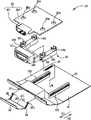
图2为本实用新型的第一实施例的滑动式连接器机构的元件分解示意图。 FIG. 2 is an exploded schematic view of the sliding connector mechanism of the first embodiment of the present invention. the
图3为本实用新型的第一实施例的滑动式连接器机构的组立图。 FIG. 3 is an assembly view of the sliding connector mechanism of the first embodiment of the present invention. the
图4与图5分别为本实用新型的第一实施例的滑动式连接器机构于不同操作状态的部分结构侧视图。 4 and 5 are partial structural side views of the sliding connector mechanism in different operating states according to the first embodiment of the present invention. the
图6与图7分别为本实用新型的第一实施例的滑动式连接器机构于不同操作状态的部分结构侧视图。 6 and 7 are partial structural side views of the sliding connector mechanism in different operating states according to the first embodiment of the present invention. the
图8为本实用新型的第二实施例的滑动式连接器机构的元件分解示意图。 FIG. 8 is an exploded schematic view of the sliding connector mechanism of the second embodiment of the present invention. the
图9为本实用新型的第二实施例的滑动式连接器机构的组立图。 FIG. 9 is an assembly view of the sliding connector mechanism of the second embodiment of the present invention. the
图10为本实用新型的第二实施例的轨道结构的俯视图。 Fig. 10 is a top view of the track structure of the second embodiment of the present invention. the
图11为本实用新型的第二实施例的轨道结构的剖视图。 Fig. 11 is a cross-sectional view of the track structure of the second embodiment of the present invention. the
其中,附图标记说明如下: Among them, the reference signs are explained as follows:

具体实施方式Detailed ways
请参阅图1,图1为本实用新型的第一实施例的一薄型可携式电子装置10的外观示意图。薄型可携式电子装置10可为一薄型笔记本电脑或一薄型平板电脑。本实用新型的薄型可携式电子装置10包含有一壳体12及一滑动式连接器机构14。壳体12用以容置多个电子元件,例如中央处理器、硬盘、存储器等组件。薄型可携式电子装置10的结构特征在于其壳体12的一侧边的厚度实质上小于壳体12的中间区域的厚度,以使壳体12可于边缘削薄,呈现轻巧造型的外观设计。 Please refer to FIG. 1 . FIG. 1 is a schematic view of a thin portable
为了搭配薄型可携式电子装置10的结构需求,滑动式连接器机构14设置于壳体12的侧边的内部,用以连接外接式连接器。于非使用状态时,滑动式连接器机构14隐藏在薄型可携式电子装置10的壳体12内部;欲使用滑动式连接器机构14时,使用者可驱动滑动式连接器机构14相对壳体12向外滑动,以使部分的滑动式连接器机构14可凸出薄型可携式电子装置10的壳体12,便于安插一外接式连接器,例如USB接头、网络线接头等等。 In order to meet the structural requirements of the thin portable
请参阅图2与图3,图2为本实用新型的第一实施例的滑动式连接器机构14的元件分解示意图,图3为本实用新型的第一实施例的滑动式连接器机构14的组立图。滑动式连接器机构14包含有一底座16,设置于壳体12内, 一基座18,以可相对滑动方式设置于底座16,一连接器20,设置于基座18上,以及一门盖22,以可活动方式设置于底座16且连接至基座18。底座16可具有一容置空间161,且容置空间161的尺寸相应门盖22的尺寸,因此门盖22可紧密闭阖至容置空间161上,以防止异物通过底座16掉入壳体12内部。连接器20可包含有一接头201,以及一电路板203,其连接于接头201。外接式连接器可于连接器20局部凸出壳体12时连接至接头201,以与电路板203电性导通。 Please refer to FIG. 2 and FIG. 3, FIG. 2 is an exploded view of the components of the sliding
基座18可包含有一遮罩结构181,用来包覆接头201以提供保护,且遮罩结构181位于邻近容置空间161的位置,以使外接式连接器穿入容置空间161便可直接连接至接头201。基座18另可包含有多个卡勾182,分别用以扣接于电路板203上相对应的固定孔204,借此限制连接器20相对基座18的移动。然而本实用新型的滑动式连接器机构14另可使用其他固定机构将连接器20安装至基座18上,例如利用锁固螺丝、铆钉结构、粘胶贴合等,其应用态样端视使用需求而定,故于此不再详述。 The base 18 may include a
此外,基座18另可包含有多条导槽结构183,且底座16可包含有相应数量的滑轨结构163。于第一实施例中,基座18与底座16分别配置有两组导槽结构183及滑轨结构163,且基座18可借由导槽结构183与滑轨结构163的组合而以可相对滑动方式设置于底座16上。基座18与连接器20的初始位置时位于壳体12的内部,且门盖22覆盖于容置空间161上以避免异物通过容置空间161接触到连接器20。使用者欲将外接式连接器连接至滑动式连接器机构14时,可将门盖22相对底座16活动以翻转出容置空间161(意即远离容置空间161),借此驱动基座18相对底座16沿着一第一方向D1滑动,以使连接器20可随着基座18的移动自壳体12的内部移动到壳体12的外部,以便于安插外接式连接器。 In addition, the
如图2所示,第一实施例的滑动式连接器机构14的门盖22可通过一枢转轴24枢接于底座16。门盖22可包含有二导引臂26,分别设置于枢转轴24的两端。各导引臂26可具有一滑槽结构261,用以套接于基座18的相应滑动销184。因此当门盖22相对底座16枢转时,导引臂26可推动滑动销184以使其沿着滑槽结构261滑移,进而对基座18施加一推力以改变基座18相对底座16的位置关系。此外,第一实施例的滑动式连接器机构14另可包含 有一弹性元件28,其两端分别设置于基座18与底座16的固定构件上,例如卡勾。使用者翻转门盖22以驱动基座18沿着第一方向D1相对底座16移动时,弹性元件28可被拉伸而存储一弹性回复力;而当施加于基座18的外力卸除,弹性元件28的弹性回复力即可用来驱动基座18沿着相反第一方向D1的一第二方向相对底座16滑动,以带动连接器20回复至初始位置,意即将连接器20滑入壳体12的内部。 As shown in FIG. 2 , the
于第一实施例中,滑动式连接器机构14另具有限制门盖22相对底座16枢转范围的结构设计。请参阅图4与图5,图4与图5分别为本实用新型的第一实施例的滑动式连接器机构14于不同操作状态沿A-A’线(如图3所示)的部分结构侧视图。门盖22可具有一限位件221,位于门盖22底部邻近底座16的一位置,且底座16可具有一挡块165,位于相应限位件221的一位置。当门盖22相对底座16外翻时,如图4所示,限位件221可用以抵接于挡块165的一外侧,其作用为防止因基座18被弹性元件28的牵引力拉扯,而带动门盖22闭阖至容置空间161上,借此限制门盖22相对底座16的枢转,将连接器20维持于有部分结构外凸壳体12的位置。另一方面,欲关上门盖22时,使用者以外力推动门盖22,以使限位件221可通过弹性变形的方式自挡块165的外侧移动至挡块165的一内侧,如图5所示,借此解除门盖22相对底座16的枢转限制,以使门盖22可利用弹性元件28驱动基座18沿第二方向D2的移动而紧密闭阖至容置空间161上,完成连接器20的收纳动作。 In the first embodiment, the sliding
请参阅图6与图7,图6与图7分别为本实用新型的第一实施例的滑动式连接器机构14于不同操作状态沿B-B’线(如图3所示)的部分结构侧视图。如图6所示,当基座18及连接器20处于壳体12内部(初始位置)时,弹性元件28没有受到外力拉扯而变形,此时门盖22闭阖于容置空间161上,以防止灰尘掉入壳体12内而造成连接器20接触不良损毁。 Please refer to Fig. 6 and Fig. 7, Fig. 6 and Fig. 7 respectively show the partial structure of the sliding
当使用者将门盖22相对底座16向外翻转,导引臂26可驱动滑动销184沿着滑槽结构261滑行,以使导引臂26可通过滑动销184来推动基座18沿着第一方向D1相对底座16滑出壳体12外,如图7所示,此时弹性元件28产生拉伸变形,且会有部分的连接器20露出壳体12,以便于使用者可易于安插外接式连接器。另一方面,欲将连接器20收回至壳体12内部时,使用者则可将门盖22阖阖至底座16的容置空间161,此时基座18可被使用者所 施加的外力、及弹性元件28所提供的弹性回复力的驱动及牵引而沿着第二方向D2相对底座16移动,以回复至图6所示的初始位置。 When the user turns the
请参阅图8与图9,图8为本实用新型的第二实施例的滑动式连接器机构14的元件分解示意图,图9为本实用新型的第二实施例的滑动式连接器机构14的组立图。第二实施例中,与第一实施例具有相同编号的元件具有相同的结构与功能,故于此不再详述。第二实施例的滑动式连接器机构14另可包含有一轨道结构30、一致动杆32、一挠曲件34与一推压弹簧36。轨道结构30可固设于底座16。致动杆32以可相对活动方式设置于轨道结构30上,且连接至门盖22与基座18。挠曲件34的一端(自由端341)可沿着轨道结构30滑行,且挠曲件34的另一端(固定端343)连接于致动杆32。推压弹簧36可设置于致动杆32与轨道结构30之间,用来驱动致动杆32相对轨道结构30的移动。相较第一实施例,第二实施例的滑动式连接器机构14另可选择性利用一固定元件38,例如外部的锁固螺丝,穿过电路板203的固定孔204,以将电路板203锁附于基座18的一突座185上。 Please refer to FIG. 8 and FIG. 9, FIG. 8 is an exploded view of the components of the sliding
请参阅图10与图11,图10为本实用新型的第二实施例的轨道结构30的俯视图,图11为本实用新型的第二实施例的轨道结构30的剖视图。如图10所示,轨道结构30可包含有一第一停留点301、一第二停留点302、一第一通道303以及一第二通道304。挠曲件34的自由端341可随着致动杆32相对轨道结构30滑移时,于第一停留点301、第二停留点302、第一通道303与第二通道304之间循环往复地移动。其中第一停留点301可与第一通道303及第二通道304分别形成段差结构,第二停留点302可与第一通道303及第二通道304分别形成段差结构,如图11所示,该段差结构可用来避免挠曲件34的自由端341沿着非预期方向移动。 Please refer to FIG. 10 and FIG. 11 , FIG. 10 is a top view of the
举例来说,第一停留点301与第一通道303之间的段差结构可用来防止挠曲件34的自由端341为其自身的挠曲弹性回复力驱动而自第一停留点301移动至第一通道303。使用者需对门盖22施加一外力,以带动致动杆32沿着第一方向D1相对轨道结构30移动,进而始可驱动挠曲件34的自由端341自第一停留点301移动至第一通道303。另一方面,第一停留点301与第二通道304之间的段差结构可用来避免挠曲件34的自由端341为推压弹簧36的弹性回复力驱动,而自第一停留点301移动至第二通道304。挠曲件34的 自由端341仅可单方向自第二通道304移往第一停留点301,接着再移入第一通道303。 For example, the step structure between the
除此之外,当使用者通过门盖22以沿着第二方向D2驱动致动杆32时,第二停留点302与第一通道303之间的段差结构可用来避免挠曲件34的自由端341自第二停留点302移入第一通道303。第二停留点302与第二通道304之间的段差结构可为平缓由低至高的坡面,以确保当致动杆32沿着第二方向D2推动挠曲件34移动时,挠曲件34的自由端341可自第二停留点302移动到第二通道304内,意即自由端341是以第一停留点301、第一通道303、第二停留点302及第二通道304的顺序来执行单方向的往复移动。 In addition, when the user drives the actuating
第二实施例的门盖22以可侧向滑动方式设置于底座16上。如图8与图9所示,门盖22与致动杆32可分别具有一滑轨223及导槽321,门盖22利用滑轨223与导槽321的组合以可相对滑动方式连接于致动杆32,借此门盖22便可相对底座16侧向移动而不致与其脱离。第二实施例的滑动式连接器机构14另可包含有一拉伸弹簧40,其两端分别设置于门盖22与致动杆32的固定构件上,例如卡勾,且拉伸弹簧40可以轴向套接方式安装于门盖22的一套接杆225。套接杆225用来避免拉伸弹簧40于弹性变形时扭曲歪斜,因此套接杆225可沿着拉伸弹簧40的弹性变形的轴向而设置于门盖22的内侧表面。 The door cover 22 of the second embodiment is disposed on the base 16 in a laterally slidable manner. As shown in Figure 8 and Figure 9, the
由此可知,第二实施例的滑动式连接器机构14的门盖22为一侧向移动的滑盖,当使用者将门盖22闭阖于容置空间161时,拉伸弹簧40即被拉扯而产生弹性变形,此时基座18与连接器20位于壳体12的内部;当使用者推动门盖22移出容置空间161,拉伸弹簧40的弹性回复力即可用以驱动门盖22沿着相异第一方向D1与第二方向D2的一第三方向D3相对底座16及致动杆32移动,以使门盖22往侧向移动而露出容置空间161,且基座18与连接器20可受到致动杆32的驱动沿着第一方向D1移出壳体12,便于使用者可安插外接式连接器。 It can be seen from this that the
如图8至图11所示,第二实施例的滑动式连接器机构14的基座18可随着门盖22沿着第三方向D3的侧向移动,而沿着第一方向D1及第二方向D2相对底座16滑移,以使连接器20可视使用者需求而凸出壳体12或隐蔽入壳体12的内部。详细来说,欲使用滑动式连接器机构14时,使用者可拉动门 盖22沿着第一方向D1相对底座16移动以移出容置空间161,此时门盖22可被拉伸弹簧40驱动而自动地沿着第三方向D3侧向移动,且致动杆32可同时间随着门盖22沿第一方向D1移动,以使挠曲件34的自由端341可为致动杆32所驱动而克服段差结构,并自第一停留点301移入第一通道303。 As shown in FIGS. 8 to 11 , the
当挠曲件34的自由端341移入第一通道303后,推压弹簧36用来推动致动杆32沿着第一方向D1相对滑轨结构30移动,此时挠曲件34的自由端341自第一通道303移动到第二停留点302,以使基座18及连接器20可随着致动杆32同步移动而凸出壳体12外,至此完成滑动式连接器机构14的开启程序,使用者可通过外凸的滑动式连接器机构14将外接式连接器电连接于薄型可携式电子装置10。 When the
另一方面,欲将连接器20收纳至壳体12内部时,使用者首先推动门盖22沿着相反第三方向D3的一方向侧向移动至容置空间161前方,接着沿着第二方向D2推动门盖22以将其闭阖至容置空间161上。此时致动杆32除了借由门盖22的驱动来推移基座18及连接器20进入壳体12内部,另可同时带动挠曲件34的自由端341自第二停留点302经由第二通道304移动到第一停留点301。当自由端341进入第一停留点301后,便可利用第一停留点301与第一通道303及第二通道304之间的段差结构来限制挠曲件34的移动,而使连接器20可稳固容置于壳体12的内部。值得一提的是,轨道结构30为一循环往复式的轨道设计,挠曲件34可于轨道结构30内移动时产生挠曲变形,以顺畅地于第一停留点301、第二停留点302、第一通道303以及第二通道304之间切换移动。 On the other hand, when wanting to store the
综上所述,本实用新型的薄型可携式电子装置是于壳体的侧边设置滑动式连接器机构。由于滑动式连接器机构的一结构高度实质上大于壳体侧边的一厚度,当没有要使用外接式连接器时,滑动式连接器机构可隐藏于壳体的内部深处,以使薄型可携式电子装置可具有边缘削薄,呈现轻巧造型的外观设计。需将外接式连接器连接至薄型可携式电子装置时,使用者可借由开启滑动式连接器机构的门盖,来牵引其基座与连接器自壳体的内部向外移动而部分裸露于外,以便于将外接式连接器安插至连接器的接头来完成电性导通。 To sum up, the thin portable electronic device of the present invention is provided with a sliding connector mechanism on the side of the casing. Since a structural height of the sliding connector mechanism is substantially greater than a thickness of the side of the housing, when the external connector is not used, the sliding connector mechanism can be hidden in the inner depth of the housing, so that the thin profile can be The portable electronic device may have a thin-edged appearance design with a lightweight shape. When it is necessary to connect the external connector to the thin portable electronic device, the user can open the door cover of the sliding connector mechanism to pull the base and the connector to move outward from the inside of the housing and partly exposed Externally, in order to insert the external connector into the joint of the connector to complete the electrical conduction. the
本实用新型包含有两种实施例。第一实施例的滑动式连接器机构的门盖枢接于底座,当门盖相对底座枢转时,导引臂可顺向推动基座的滑动销沿着 其滑槽结构滑行,以带动基座相对底座向外滑移,及连接器自壳体内部外移而部分裸露于外。第二实施例的滑动式连接器机构的门盖是可活动方式连接于致动杆,借此以可侧向移动方式覆盖于底座的容置空间上。当第二实施例的门盖移离容置空间,除了可利用拉伸弹簧将门盖自动往旁侧推开,致动杆亦可同时带动基座与连接器自壳体内部向外滑移,以达到可调整连接器相对壳体的位置关系的目的。 The utility model comprises two kinds of embodiments. The door cover of the sliding connector mechanism of the first embodiment is pivotally connected to the base. When the door cover pivots relative to the base, the guide arm can push the sliding pin of the base to slide along its chute structure to drive the base. The seat slides outward relative to the base, and the connector moves outward from the inside of the casing to be partially exposed outside. The door cover of the sliding connector mechanism of the second embodiment is movably connected to the actuating rod, thereby covering the accommodating space of the base in a laterally movable manner. When the door cover of the second embodiment is moved away from the accommodating space, in addition to using the tension spring to automatically push the door cover to the side, the actuating rod can also simultaneously drive the base and the connector to slide outward from the inside of the housing. In order to achieve the purpose of adjusting the positional relationship of the connector relative to the housing. the
相较于现有技术,本实用新型设计一种利用开启/闭合门盖来牵引连接器作动的滑动式连接器机构,以搭配具有侧边削薄的结构特征的薄型可携式电子装置。本实用新型的滑动式连接器机构的结构简单、操作容易,可于开关门盖时同步驱动连接器移出或退入壳体内,故可有效应用于相关的薄型可携式电子装置,达到兼具简约外观且使用方便的优点。 Compared with the prior art, the utility model designs a sliding connector mechanism that pulls the connector by opening/closing the door cover, so as to match the thin portable electronic device with the structural feature of thinned sides. The sliding connector mechanism of the utility model is simple in structure and easy to operate, and can drive the connector out or back into the casing synchronously when opening and closing the door cover, so it can be effectively applied to related thin portable electronic devices, achieving both The advantages of simple appearance and convenient use. the
以上所述仅为本实用新型的较佳实施例,凡依本实用新型权利要求所做的均等变化与修饰,皆应属本实用新型的涵盖范围。 The above descriptions are only preferred embodiments of the present utility model, and all equivalent changes and modifications made according to the claims of the present utility model shall fall within the scope of the present utility model. the
Claims (36)
Translated fromChineseApplications Claiming Priority (2)
| Application Number | Priority Date | Filing Date | Title |
|---|---|---|---|
| TW101200019UTWM432234U (en) | 2012-01-02 | 2012-01-02 | Slide connector mechanism and related thin portable electronic device |
| TW101200019 | 2012-01-02 |
Publications (1)
| Publication Number | Publication Date |
|---|---|
| CN202443359Utrue CN202443359U (en) | 2012-09-19 |
Family
ID=46724026
Family Applications (1)
| Application Number | Title | Priority Date | Filing Date |
|---|---|---|---|
| CN2012200126561UExpired - LifetimeCN202443359U (en) | 2012-01-02 | 2012-01-11 | Sliding connector mechanism and related thin portable electronic device |
Country Status (2)
| Country | Link |
|---|---|
| CN (1) | CN202443359U (en) |
| TW (1) | TWM432234U (en) |
Cited By (3)
| Publication number | Priority date | Publication date | Assignee | Title |
|---|---|---|---|---|
| CN106028698A (en)* | 2015-03-26 | 2016-10-12 | 罗伯特·博世有限公司 | Electronic housing with plug-in and withdrawable electrical connector |
| CN106068483A (en)* | 2013-07-22 | 2016-11-02 | 慧与发展有限责任合伙企业 | Module communication apparatus |
| CN108957656A (en)* | 2013-04-24 | 2018-12-07 | 泰科电子瑞侃有限公司 | For telecommunication chassis to be installed to the universal mounting mechanisms of the fixed device of telecommunications |
Families Citing this family (2)
| Publication number | Priority date | Publication date | Assignee | Title |
|---|---|---|---|---|
| TWI499145B (en)* | 2013-07-31 | 2015-09-01 | Pegatron Corp | Electronic apparatus, base and switching function of pins of a connector |
| TWI719603B (en)* | 2019-08-23 | 2021-02-21 | 緯創資通股份有限公司 | Connecting module and electronic device |
- 2012
- 2012-01-02TWTW101200019Upatent/TWM432234U/ennot_activeIP Right Cessation
- 2012-01-11CNCN2012200126561Upatent/CN202443359U/ennot_activeExpired - Lifetime
Cited By (6)
| Publication number | Priority date | Publication date | Assignee | Title |
|---|---|---|---|---|
| CN108957656A (en)* | 2013-04-24 | 2018-12-07 | 泰科电子瑞侃有限公司 | For telecommunication chassis to be installed to the universal mounting mechanisms of the fixed device of telecommunications |
| CN108957656B (en)* | 2013-04-24 | 2020-12-25 | 泰科电子瑞侃有限公司 | Universal mounting mechanism for mounting a telecommunications chassis to a telecommunications fixture |
| CN106068483A (en)* | 2013-07-22 | 2016-11-02 | 慧与发展有限责任合伙企业 | Module communication apparatus |
| CN106068483B (en)* | 2013-07-22 | 2021-03-23 | 慧与发展有限责任合伙企业 | Module connecting device |
| CN106028698A (en)* | 2015-03-26 | 2016-10-12 | 罗伯特·博世有限公司 | Electronic housing with plug-in and withdrawable electrical connector |
| CN106028698B (en)* | 2015-03-26 | 2019-09-24 | 罗伯特·博世有限公司 | Casting of electronic device with the electrical plug-in connector that can be taken in and pull out |
Also Published As
| Publication number | Publication date |
|---|---|
| TWM432234U (en) | 2012-06-21 |
Similar Documents
| Publication | Publication Date | Title |
|---|---|---|
| TWI387165B (en) | Connector mechanism capable of adjusting a height of an opening thereof | |
| CN103914103B (en) | Movable slot and related electronic device | |
| CN103296520B (en) | Connector mechanism | |
| US9398707B2 (en) | Expansion platform for portable electronic apparatus | |
| CN202443359U (en) | Sliding connector mechanism and related thin portable electronic device | |
| US8576558B2 (en) | Mounting apparatus with rotating member for retaining and buffering data storage device | |
| US20090168340A1 (en) | Housing of foldable electronic device | |
| CN103811919B (en) | connector mechanism and electronic device | |
| US9110637B2 (en) | Electronic device | |
| TWI479976B (en) | Fixing structure for interface card connector | |
| US8982551B2 (en) | Electronic device and electronic module fixing structure thereof | |
| US8848376B2 (en) | Lock structure and control mechanism and method thereof | |
| CN203085824U (en) | Connector mechanism and electronic device | |
| TWI455417B (en) | Connector mechanism for connecting a terminal | |
| TW432234B (en) | Optical signal transmission apparatus and method | |
| EP3345250B1 (en) | Extendable connector port | |
| CN102044642B (en) | Latch mechanism | |
| CN201281832Y (en) | Hard disk fixing device and electronic device using same | |
| US7740290B2 (en) | Electronic device | |
| CN102386500B (en) | Connector mechanism with adjustable opening height | |
| CN104571271A (en) | Electronic device | |
| CN100421050C (en) | Electronic device and hook linkage structure thereof | |
| CN208044503U (en) | Electronic device with drawing structure | |
| CN103633479B (en) | connector mechanism and electronic device | |
| CN100399868C (en) | Mechanism system with movable clamping hook |
Legal Events
| Date | Code | Title | Description |
|---|---|---|---|
| C14 | Grant of patent or utility model | ||
| GR01 | Patent grant | ||
| CX01 | Expiry of patent term | Granted publication date:20120919 | |
| CX01 | Expiry of patent term |