CN202421768U - Multifunctional time synchronization calibrator for electric power systems - Google Patents
Multifunctional time synchronization calibrator for electric power systemsDownload PDFInfo
- Publication number
- CN202421768U CN202421768UCN 201120528495CN201120528495UCN202421768UCN 202421768 UCN202421768 UCN 202421768UCN 201120528495CN201120528495CN 201120528495CN 201120528495 UCN201120528495 UCN 201120528495UCN 202421768 UCN202421768 UCN 202421768U
- Authority
- CN
- China
- Prior art keywords
- module
- input
- output
- time
- output module
- Prior art date
- Legal status (The legal status is an assumption and is not a legal conclusion. Google has not performed a legal analysis and makes no representation as to the accuracy of the status listed.)
- Expired - Lifetime
Links
Images


Landscapes
- Electric Clocks (AREA)
Abstract
Translated fromChinese
Description
Technical field
The utility model belongs to industrial automation time synchronized calibration technology field, especially is applied in the Multi-function Time synchronization check instrument of secondary device in the electric system.
Background technology
Unified clock is self-evident to electric system in monitoring in real time, importance at aspects such as line computation, crash analysis, statistics filings; Go deep into along with what the Big Dipper, gps satellite clock were used; Make the whole network unified clock become possibility, each Utilities Electric Co. of the whole nation just is being devoted to this work at present.Want to reach the whole network unified clock truly; Have two important steps strict to control: one provide clock equipment gps clock device for example; Another is the equipment of applied clock, for example secondary automation equipments such as protective device, fault wave recording device, travelling wave ranging device, vector measurement device.How are the accuracy of all kinds clock signal that Synchronization Clock provides and degree of stability? Does the time mark of each secondary device data in the use of clock have bias free? Sequence of events recording SOE etc. for example.The situation of electric system at present is that secondary device is of a great variety; There are protection kind equipment, power remote monitor class, metering class, phasor measurement class, record ripple record class, thunder and lightning to measure class, quality of power supply class etc.; The required temporal information and the interface type of time signal are also a lot; Need a kind of existing electric system required temporal information and the time synchronized tester of time signal of containing of design, the while is lightly portable, reserve battery is arranged, be applicable to various on-the-spot test, the verification environment.Existing time synchronized tester and similar products; Main deficiency is only to adopt the frequency measurement comparison of gps clock, limited, the no alternating voltage of interface type (civil power), can't accomplish to accomplish the time synchronized verification to various secondary devices in transformer station, the generating plant with an instrument.Need a kind of tester lock in time that meets the electric system demand to solve these problems.Literature search finds, with the utility model the most approaching be that one Chinese patent application number is the patented claim for " portable event journal and time synchronization check appearance " of 200910051487.5 exercise question.It to the effect that utilizes GPS receiver module, central processing unit to handle test speed-sensitive switch amount input channel temporal resolution and Channel Response Time; But the utility model and its are different on utility model purpose, technical solution.
The utility model content
The purpose of the utility model provides a kind of electric system demand that meets, and contains the portable multi-function time synchronized tester of existing electric system required time information and time signal and all kinds of interface channel and protocol type.
Realize that the technical scheme that the utility model above-mentioned purpose is adopted is: multifunction power system time synchronization check appearance comprises ARMmodule 1,FPGA module 2, satellitetime receiver module atomic clock module 5, time signal input/output module, alternating voltage input/output module 13, high-speed a/d module 14,communication module Keysheet module 20,supply module time receiver module satellite receiver module 4, gpssatellite receiver module 3; Said time signal input/output module comprises passive time pulse input/output module 6, active time pulse input/output module 7, multimode optical fiber input/output module 8, single-mode fiber input/output module 9, TTL signal input/output module 10, RS-485 signal input/output module 11, alternating-current B sign indicating number input/output module 12; Said communication module comprises PTP/NTP/SNTPnetwork communication module 19, RS-232/422communication module 18; Touch-screen,Keysheet module 20 comprise touch screen module, Keysheet module; Supply module comprises working power module, battery module, DC voltage source module.
Said big-dippersatellite receiver module 4, gpssatellite receiver module 3, rubidiumatomic clock module 5, passive time pulse input/output module 6, active time pulse input/output module 7, multimode optical fiber input/output module 8, single-mode fiber input/output module 9, TTL signal input/output module 10, RS-485 signal input/output module 11, alternating-current B sign indicating number input/output module 12, alternating voltage input/output module 13, high-speed a/d module 14 all are connected toFPGA module 2; Said PTP/NTP/SNTPnetwork communication module 19, RS-232/422communication module 18, touch-screen,Keysheet module 20 all are connected to ARMmodule 1; SaidFPGA module 2 connects ARMmodule 1 through parallel bus.
SaidFPGA module 2 realizes GPS through the programmable digital logic circuit; Big Dipper temporal information and timesignal processing module 201; Rubidium atomic clock istamed module 202; Internalclocking base modules 203; Multipath clockcompensation output module 204; High-speed a/d sampling andmemory module 205; I/O passage and agreement associatedselection module 206;Frequency signal module 207;PPS pulse module 208;PPM pulse module 209;PPH pulse module 210; IRIG-B-DC module 211; IRIG-B-AC module 212;DCF77 module 213; The functions of modules of alternatingvoltage frequency module 214.
Said I/O passage and agreement associatedselection module 206 can be according to the setting of project to be tested automatically with the for example passive time pulse input/output modules 6 in I/O physical channel; Active time pulse input/output module 7; Multimode optical fiber input/output module 8; Single-mode fiber input/output module 9; TTL signal input/output module 10; RS-485 signal input/output module 11; Alternating-current B sign indicating number input/output module 12; Alternating voltage input/output module 13 and signaling protocol such asfrequency signal module 207;PPS pulse module 208;PPM pulse module 209;PPH pulse module 210; IRIG-B-DC module 211; IRIG-B-AC module 212;DCF77 module 213; Alternatingvoltage frequency module 214 associated selection together.
Saidfrequency signal module 207,PPS pulse module 208,PPM pulse module 209,PPH pulse module 210, IRIG-B-DC module 211, IRIG-B-AC module 212,DCF77 module 213, alternatingvoltage frequency module 214 include that separately input signal is resolved and the output signal generates two parts, fix to guarantee that time signal and temporal information are transmitted in time, delayed time in the utility model.
The utility model multifunction power system time synchronization check appearance can be realized following test verification project under its software support:
A) UTC is provided the standard time;
B) PPS, PPM, PPH, IRIG-B-DC, IRIG-B-AC, DCF77 equal time signal and the temporal information of standard are provided;
C) time signal of test clock equipment output time-delay;
D) the time signal transmission of test clock equipment time-delay;
E) test clock equipment time bias ability;
F) the punctual precision of test clock equipment;
G) stability of the time signal of test clock equipment output;
H) Test Switchboard amount acquisition precision;
I) collection of Test Switchboard amount goes to tremble time-delay;
J) the test automation device to the time result;
K) the signal jumping moment is left in test;
L) pulsewidth of test pulse signal, cycle and frequency;
M) test unlike signal, the different time difference of triggering;
N) frequency difference of test signal;
O) test 220V alternating voltage frequency;
Compare with prior art, significant advantage and good effect are arranged.
Description of drawings
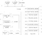
Fig. 1 is the described multifunction power system time of a utility model synchronization check instrument system structured flowchart synoptic diagram.
Fig. 2 is the described FPGA programmable digital logic circuit block diagram synoptic diagram of the utility model.
Fig. 3 is the described tester course of work of a utility model embodiment synoptic diagram.
Embodiment
In conjunction with accompanying drawing and embodiment the utility model is done further explanation.
Referring to Fig. 1, Fig. 2, Fig. 3; Multifunction power system time synchronization check appearance be can know from Fig. 1,ARM module 1,FPGA module 2, satellitetime receiver module atomic clock module 5, time signal input/output module, alternating voltage input/output module 13, high-speed a/d module 14,communication module Keysheet module 20,supply module module 1 adopted is TI AM3517 Cortex-A8 chip; WhatFPGA module 2 adopted is Xilinx XC3S1400AN chip, and that rubidiumatomic clock module 5 adopts is Symmetricom SA.33m.
SA.33M is the rubidium oscillator of miniaturization, and their size is consistent with some constant-temperature crystal oscillators of symmetricom company with the stitch design, so that substitute constant-temperature crystal oscillator.Have the performance of atomic oscillator, volume is little, advantage low in energy consumption.Signal output: 10 MHz square-wave signals, 3.3V ACMOS level, Vl < 0.5V, Vh>2.7V15pf load, rising/fall time: < 10ns, dutycycle: 50% ± 10%; What said high-speed a/>d module 14 present embodiments adopted is Analog Devices AD9288 model.
Satellitetime receiver module satellite receiver module 4, gpssatellite receiver module 3; The big-dipper satellite receiver module adopts BD-6 S2 model, and the gps satellite receiver module adopts U_BLOX 6T model; Said time signal input/output module comprises passive time pulse input/output module 6, active time pulse input/output module 7, multimode optical fiber input/output module 8, single-mode fiber input/output module 9, TTL signal input/output module 10, RS-485 signal input/output module 11, alternating-current B sign indicating number input/output module 12; Said communication module comprises PTP/NTP/SNTPnetwork communication module 19, RS-232/422communication module 18; Touch-screen,Keysheet module 20 comprise touch screen module, Keysheet module; Supply module comprises working power module, battery module, DC voltage source module; Voltage 110 ~ 220V alternating current-direct current self-adaptation of working power module, battery module voltage is 12V, the DC voltage source module is 5V ~ 230V scalable output.
Big-dippersatellite receiver module 4, gpssatellite receiver module 3, rubidiumatomic clock module 5, passive time pulse input/output module 6, active time pulse input/output module 7, multimode optical fiber input/output module 8, single-mode fiber input/output module 9, TTL signal input/output module 10, RS-485 signal input/output module 11, alternating-current B sign indicating number input/output module 12, alternating voltage input/output module 13, high-speed a/d module 14 all are connected toFPGA module 2; Said PTP/NTP/SNTPnetwork communication module 19, RS-232/422communication module 18, touch-screen,Keysheet module 20 all are connected to ARMmodule 1; SaidFPGA module 2 connects ARMmodule 1 through parallel bus.
Fig. 2 has illustrated saidFPGA module 2 to realize GPS through the programmable digital logic circuit; Big Dipper temporal information and timesignal processing module 201; Rubidium atomic clock istamed module 202; Internalclocking base modules 203; Multipath clockcompensation output module 204; High-speed a/d sampling andmemory module 205; I/O passage and agreement associatedselection module 206;Frequency signal module 207;PPS pulse module 208;PPM pulse module 209;PPH pulse module 210; IRIG-B-DC module 211; IRIG-B-AC module 212;DCF77 module 213; The functions of modules of alternatingvoltage frequency module 214.
Saidfrequency signal module 207,PPS pulse module 208,PPM pulse module 209,PPH pulse module 210, IRIG-B-DC module 211, IRIG-B-AC module 212,DCF77 module 213, alternatingvoltage frequency module 214 include that separately input signal is resolved and the output signal generates two parts.Above-mentioned each module is all closed with I/O passage and agreement associated selection module lotus root, and for example I/O passage and agreement associatedselection module 206 can be according to the setting of project to be tested automatically with the passive time pulse input/output module in I/O physical channel, active time pulse input/output module, multimode optical fiber input/output module, single-mode fiber input/output module, TTL signal input/output module, RS-485 signal input/output module, alternating-current B sign indicating number input/output module, alternating voltage input/output module and signaling protocol frequency signal module, PPS pulse module, PPM pulse module, PPH pulse module, IRIG-B-DC module, IRIG-B-AC module, DCF77 module, alternating voltage frequency module associated selection together.In the utility model, transmit in time, delay time fixing to guarantee time signal and temporal information.
GPS, Big Dipper temporal information and time signal processing module utilize gps satellite time receiver module, big-dipper satellite time receiver module to receive satellite time simultaneously; Can the UTC time precision that provide be brought up to 50ns from 100ns along constantly doing the Gaussian distribution statistics second to separately.
Rubidium atomic clock is tamed the PPS that module provides through the internal clocking base modules, and the PPS and the 10MHz that adopt taming algorithm to make the taming module of rubidium atomic clock offer the internal clocking base modules overlap with its rising edge to greatest extent.When whole external clocks disappeared, the internal clocking base modules can provide inner punctual temporal information and time signal.
Multipath clockcompensation output module 204 receives the internal standard time signal that internalclocking base modules 203 provides, and according to each paths different delayed time, exports the different make-up time signals in each road, guarantees that each passage I/O porch time is consistent.
The alternating voltage input/output module can provide 50~250V/40~60Hz standard sine wave output circuit and input ac voltage frequency measurement, and 2 the tunnel at a high speed 8 A/D modules can 800MHz sampling rate write input waveform, is used for observation, analyzes.
The technical performance index that the utility model reaches is following:
Time precision measuring resolution: 0.2ns;
Precision is tamed in the frequency marking source: 1.1 * 10-11After 1 hour;
Environment for use: working temperature-10 ℃~+ 50 ℃;
Output time precision: PPS/PPM/PPH ± 15ns, IRIG-B-DC ± 15ns, DCF77 ± 15ns, IRIG-B-AC ± 100ns;
Time signal measuring accuracy: 20ns;
Time reference and standard UTC error: less than 50ns.
National Energy Board in 2009 issue power industry standard " the clock synchronization system first of electric system: technical manual " in, stipulated that time signal should comprise special signals such as pulse signal, IRIG-B sign indicating number, serial port time message, network time message.IRIG-B is meant that IRIG (U.S. the Inter-Range Instrumentation Group) has A, B, D, E, G, several kinds of coding standards of H (IRIG Standard 200-98).Wherein in clock synchronization is used, using maximum is the IRIG-B coding.
Fig. 3 has illustrated the described tester course of work of the utility model embodiment, is example with the test of IRIG-B time signal: press Fig. 3 mode with time signal from equipment under test synchronization check turn-on time appearance, the input interface type can be one of following type:
– Transistor-Transistor Logic level mode;
– idle contact mode;
– RS-485/RS-422 differential interface;
– optical fiber interface (single mode, multimode).
Content measurement comprises: on time along the rise time, on time along error, positive pulsewidth, code-element period, stability measurement,
Carrier frequency, amplitude, modulation ratio, output impedance IRIG-B-AC; And can verify IRIG-B timecode information correctness: comprise local time information, B code check position, time-zone information, temporal quality information, leap second identification information, SBS information.
Claims (4)
Translated fromChinesePriority Applications (1)
| Application Number | Priority Date | Filing Date | Title |
|---|---|---|---|
| CN 201120528495CN202421768U (en) | 2011-12-16 | 2011-12-16 | Multifunctional time synchronization calibrator for electric power systems |
Applications Claiming Priority (1)
| Application Number | Priority Date | Filing Date | Title |
|---|---|---|---|
| CN 201120528495CN202421768U (en) | 2011-12-16 | 2011-12-16 | Multifunctional time synchronization calibrator for electric power systems |
Publications (1)
| Publication Number | Publication Date |
|---|---|
| CN202421768Utrue CN202421768U (en) | 2012-09-05 |
Family
ID=46746513
Family Applications (1)
| Application Number | Title | Priority Date | Filing Date |
|---|---|---|---|
| CN 201120528495Expired - LifetimeCN202421768U (en) | 2011-12-16 | 2011-12-16 | Multifunctional time synchronization calibrator for electric power systems |
Country Status (1)
| Country | Link |
|---|---|
| CN (1) | CN202421768U (en) |
Cited By (10)
| Publication number | Priority date | Publication date | Assignee | Title |
|---|---|---|---|---|
| CN102520609A (en)* | 2011-12-16 | 2012-06-27 | 四川省电力公司通信自动化中心 | Multifunctional electric power system time synchronization calibration instrument |
| CN102880045A (en)* | 2012-09-17 | 2013-01-16 | 南京澳德思电气有限公司 | Synchronous clock time output system based on global positioning system (GPS), compass satellite, optical fiber B code and high-accuracy constant-temperature crystal oscillator |
| CN103595582A (en)* | 2013-11-08 | 2014-02-19 | 贵州电力试验研究院 | High-accuracy synchronous system detection device applied to intelligent transformer substation |
| CN104820362A (en)* | 2015-05-26 | 2015-08-05 | 武汉华中天纬光电系统有限公司 | Portable time system detector |
| CN105549380A (en)* | 2016-01-28 | 2016-05-04 | 安徽四创电子股份有限公司 | Multi-mode high-precision timing system and method |
| CN105700336A (en)* | 2016-04-07 | 2016-06-22 | 山东和远智能科技股份有限公司 | Electric power instrument time calibrating method based on RS485 bus connection |
| CN106647228A (en)* | 2016-12-05 | 2017-05-10 | 许继集团有限公司 | Convertor station master clock fault determination system |
| CN106896710A (en)* | 2017-04-07 | 2017-06-27 | 成都府河电力自动化成套设备有限责任公司 | Scene configurable time synchronization test system and implementation method |
| CN114137819A (en)* | 2021-12-06 | 2022-03-04 | 上海珉嵘科技有限公司 | Clock frequency deviation adjusting device and method and satellite signal acquisition preprocessing board card |
| CN114282496A (en)* | 2021-12-09 | 2022-04-05 | 国电南瑞科技股份有限公司 | Generation method and display method of fault recording file |
- 2011
- 2011-12-16CNCN 201120528495patent/CN202421768U/ennot_activeExpired - Lifetime
Cited By (14)
| Publication number | Priority date | Publication date | Assignee | Title |
|---|---|---|---|---|
| CN102520609A (en)* | 2011-12-16 | 2012-06-27 | 四川省电力公司通信自动化中心 | Multifunctional electric power system time synchronization calibration instrument |
| CN102880045A (en)* | 2012-09-17 | 2013-01-16 | 南京澳德思电气有限公司 | Synchronous clock time output system based on global positioning system (GPS), compass satellite, optical fiber B code and high-accuracy constant-temperature crystal oscillator |
| CN102880045B (en)* | 2012-09-17 | 2014-01-29 | 南京澳德思电气有限公司 | Synchronous clock time output system based on global positioning system (GPS), compass satellite, optical fiber B code and high-accuracy constant-temperature crystal oscillator |
| CN103595582A (en)* | 2013-11-08 | 2014-02-19 | 贵州电力试验研究院 | High-accuracy synchronous system detection device applied to intelligent transformer substation |
| CN103595582B (en)* | 2013-11-08 | 2015-06-17 | 贵州电力试验研究院 | High-accuracy synchronous system detection device applied to intelligent transformer substation |
| CN104820362A (en)* | 2015-05-26 | 2015-08-05 | 武汉华中天纬光电系统有限公司 | Portable time system detector |
| CN105549380A (en)* | 2016-01-28 | 2016-05-04 | 安徽四创电子股份有限公司 | Multi-mode high-precision timing system and method |
| CN105700336A (en)* | 2016-04-07 | 2016-06-22 | 山东和远智能科技股份有限公司 | Electric power instrument time calibrating method based on RS485 bus connection |
| CN106647228A (en)* | 2016-12-05 | 2017-05-10 | 许继集团有限公司 | Convertor station master clock fault determination system |
| CN106647228B (en)* | 2016-12-05 | 2020-06-16 | 许继集团有限公司 | A fault judgment system for the master clock of a converter station |
| CN106896710A (en)* | 2017-04-07 | 2017-06-27 | 成都府河电力自动化成套设备有限责任公司 | Scene configurable time synchronization test system and implementation method |
| CN114137819A (en)* | 2021-12-06 | 2022-03-04 | 上海珉嵘科技有限公司 | Clock frequency deviation adjusting device and method and satellite signal acquisition preprocessing board card |
| CN114137819B (en)* | 2021-12-06 | 2023-11-03 | 上海珉嵘科技有限公司 | Clock frequency offset adjusting device and method and satellite signal acquisition preprocessing board card |
| CN114282496A (en)* | 2021-12-09 | 2022-04-05 | 国电南瑞科技股份有限公司 | Generation method and display method of fault recording file |
Similar Documents
| Publication | Publication Date | Title |
|---|---|---|
| CN202421768U (en) | Multifunctional time synchronization calibrator for electric power systems | |
| CN102520609A (en) | Multifunctional electric power system time synchronization calibration instrument | |
| CN103278791B (en) | The electronic mutual inductor amplitude phase error check system that Networkable detects | |
| Zhao et al. | GPS-disciplined analog-to-digital converter for phasor measurement applications | |
| CN202443082U (en) | Merging unit test system with analog input and university | |
| Moreno-Munoz et al. | Embedding synchronized measurement technology for smart grid development | |
| CN203909162U (en) | Electric energy quality collection apparatus | |
| CN103197145B (en) | Method and system of ultrahigh resolution phase difference measurement | |
| CN202008583U (en) | Clock source of synchronous phasor measuring device | |
| CN202033470U (en) | Digital electric energy meter calibration system | |
| CN103869182B (en) | The combining unit transient test system controlled based on the Precise Discrete time | |
| CN104360298A (en) | Performance test system and method for merging unit tester | |
| CN201708809U (en) | IEEE1588 time testing analyzer | |
| CN106771599B (en) | Test setup for synchrophasor measurement devices in smart substations | |
| CN102298099A (en) | Power distribution and consumption monitoring and measuring apparatus possessing time calibration function | |
| CN104155545A (en) | Multichannel analog quantity acquisition module based on GPS signals | |
| CN104880624A (en) | Wireless test system used for transformer substation system debugging and wireless measurement method used for transformer substation system debugging | |
| CN202217149U (en) | High-precision electric power time synchronizer | |
| CN105388780B (en) | An IRIG-B000 code simulation device | |
| CN104297593A (en) | Punctuality error detection method for intelligent substation merging unit | |
| CN204256149U (en) | A kind of Performance Test System of merge cells tester | |
| CN209072515U (en) | Clockwork detection system | |
| CN102436172A (en) | Multifunctional watt-hour meter and GPS timing system | |
| CN210109209U (en) | A synchrophasor measuring device for distribution network | |
| CN204903668U (en) | Intelligent substation small -signal communication simulation merging cells accuracy test equipment |
Legal Events
| Date | Code | Title | Description |
|---|---|---|---|
| C14 | Grant of patent or utility model | ||
| GR01 | Patent grant | ||
| ASS | Succession or assignment of patent right | Owner name:STATE ELECTRIC NET CROP. Effective date:20130820 | |
| C41 | Transfer of patent application or patent right or utility model | ||
| TR01 | Transfer of patent right | Effective date of registration:20130820 Address after:610020, 50 pear flower street, Chengdu, Sichuan, Jinjiang District Patentee after:China Electric Power Research Institute Patentee after:State Grid Corporation of China Address before:610020, 50 pear flower street, Chengdu, Sichuan, Jinjiang District Patentee before:China Electric Power Research Institute | |
| CX01 | Expiry of patent term | ||
| CX01 | Expiry of patent term | Granted publication date:20120905 |