CN202378885U - Air conditioning air duct system for intercity motor train unit - Google Patents
Air conditioning air duct system for intercity motor train unitDownload PDFInfo
- Publication number
- CN202378885U CN202378885UCN2011205101250UCN201120510125UCN202378885UCN 202378885 UCN202378885 UCN 202378885UCN 2011205101250 UCN2011205101250 UCN 2011205101250UCN 201120510125 UCN201120510125 UCN 201120510125UCN 202378885 UCN202378885 UCN 202378885U
- Authority
- CN
- China
- Prior art keywords
- air
- duct
- car
- outlet
- return
- Prior art date
- Legal status (The legal status is an assumption and is not a legal conclusion. Google has not performed a legal analysis and makes no representation as to the accuracy of the status listed.)
- Expired - Lifetime
Links
- 238000004378air conditioningMethods0.000titleclaimsabstractdescription35
- 230000003068static effectEffects0.000claimsdescription7
- 239000000463materialSubstances0.000claimsdescription6
- XAGFODPZIPBFFR-UHFFFAOYSA-NaluminiumChemical compound[Al]XAGFODPZIPBFFR-UHFFFAOYSA-N0.000claimsdescription4
- 229910052782aluminiumInorganic materials0.000claimsdescription4
- 239000011152fibreglassSubstances0.000claimsdescription3
- 238000009423ventilationMethods0.000claims2
- 239000004411aluminiumSubstances0.000claims1
- 238000007664blowingMethods0.000claims1
- 239000002699waste materialSubstances0.000abstractdescription55
- 230000009286beneficial effectEffects0.000description3
- 238000010586diagramMethods0.000description3
- 238000009826distributionMethods0.000description3
- 239000007789gasSubstances0.000description3
- 238000001704evaporationMethods0.000description2
- 238000012986modificationMethods0.000description2
- 230000004048modificationEffects0.000description2
- 239000002912waste gasSubstances0.000description2
- 241000271559DromaiidaeSpecies0.000description1
- 238000005054agglomerationMethods0.000description1
- 230000002776aggregationEffects0.000description1
- 238000004519manufacturing processMethods0.000description1
- 238000000034methodMethods0.000description1
- 239000013585weight reducing agentSubstances0.000description1
Images


Classifications
- Y—GENERAL TAGGING OF NEW TECHNOLOGICAL DEVELOPMENTS; GENERAL TAGGING OF CROSS-SECTIONAL TECHNOLOGIES SPANNING OVER SEVERAL SECTIONS OF THE IPC; TECHNICAL SUBJECTS COVERED BY FORMER USPC CROSS-REFERENCE ART COLLECTIONS [XRACs] AND DIGESTS
- Y02—TECHNOLOGIES OR APPLICATIONS FOR MITIGATION OR ADAPTATION AGAINST CLIMATE CHANGE
- Y02T—CLIMATE CHANGE MITIGATION TECHNOLOGIES RELATED TO TRANSPORTATION
- Y02T30/00—Transportation of goods or passengers via railways, e.g. energy recovery or reducing air resistance
Landscapes
- Air-Conditioning For Vehicles (AREA)
Abstract
Translated fromChinese
Description
Translated fromChinese技术领域technical field
本实用新型涉及一种空调风道系统,特别涉及一种在城际动车组上使用的空调风道系统,属于轨道车辆空调制造技术领域。The utility model relates to an air-conditioning air duct system, in particular to an air-conditioning air duct system used on an intercity EMU, and belongs to the technical field of rail vehicle air-conditioning manufacturing.
背景技术Background technique
城际动车组是为了满足我国区域经济快速发展和城市群崛起对城轨交通的要求新开发的一种车型,具有载客量大、快速起停等特点,无论速度还是设计结构都与以往车型有较大区别,因此只有针对城际列车的实际情况设计研制适宜的空气调节系统,才能使客车内的空气参数和空气品质达到要求,为旅客提供舒适的旅行环境。目前国内列车送风风道系统一般都采用安装于车顶端部位置,送风系统采用顶部静压腔送风形式,且没有独立的回风道、废排风道。此种空调风道系统车内微风速和温度分布均匀性较差。其次,200km/h城际车的高速行驶,对气密性也较高,现有的空调风道系统无法满足对气密性的更高的要求。The intercity EMU is a newly developed model to meet the requirements of the rapid regional economic development and the rise of urban agglomerations in my country. It has the characteristics of large passenger capacity, fast start and stop, etc., and is different from previous models in terms of speed and design structure. Therefore, only by designing and developing a suitable air-conditioning system for the actual situation of intercity trains can the air parameters and air quality in passenger cars meet the requirements and provide passengers with a comfortable travel environment. At present, the domestic train air supply duct system is generally installed at the top of the car. The air supply system adopts the air supply form of the top static pressure chamber, and there is no independent return air duct and waste exhaust duct. This kind of air-conditioning duct system has poor wind speed and temperature distribution uniformity in the car. Secondly, the high-speed driving of 200km/h intercity vehicles also has high air tightness, and the existing air-conditioning duct system cannot meet the higher requirements for air tightness.
发明内容Contents of the invention
本实用新型主要目的在于解决上述问题,提供了一种气密性好,送风均匀,并能满足车辆轻量化要求的城际动车组用空调风道系统。The main purpose of the utility model is to solve the above problems, and to provide an air-conditioning duct system for an intercity EMU with good air tightness, uniform air supply, and meeting the requirements of light weight vehicles.
为实现上述目的,本实用新型的技术方案是:In order to achieve the above object, the technical solution of the utility model is:
一种城际动车组用空调风道系统,包括设置于车顶的空调机组和设置于车底的废排机组;所述空调机组室内侧的出风口和进风口分别通过设置于车顶的送风风道和回风风道与位于车内的送风口和回风口连通,所述车内的送风口至少包括客室车厢内的送风口、卫生间的送风口及司机室内的送风口,所述车内的回风口至少包括客室车厢内的回风口及司机室的回风口;所述废排机组通过废排风道与位于车内的废排风口连通,所述车内的废排风口至少包括客室车厢内的废排风口及卫生间内的废排风口。An air-conditioning air duct system for an intercity EMU, comprising an air-conditioning unit arranged on the roof and a waste discharge unit arranged at the bottom of the car; the air outlet and the air inlet on the indoor side of the air-conditioning unit pass The air duct and the return air duct communicate with the air supply port and the return air port located in the car, and the air supply ports in the car at least include the air supply port in the passenger compartment, the air supply port in the toilet and the air supply port in the driver's compartment. The return air outlet in the interior includes at least the air return outlet in the passenger compartment and the air return outlet in the driver's cab; Including the waste air outlet in the passenger compartment and the waste air outlet in the bathroom.
进一步,所述送风风道和回风风道沿车体长度方向设置,所述送风风道位于中间,所述回风风道设置于所述送风风道的两侧,所述送风风道和/或所述回风风道由客室车厢一直延伸至司机室内。Further, the air supply duct and the air return duct are arranged along the length direction of the vehicle body, the air supply duct is located in the middle, the return air duct is arranged on both sides of the air supply duct, and the air supply duct is arranged on both sides of the air supply duct. The air duct and/or the return air duct extend from the passenger compartment to the driver's compartment.
进一步,所述送风风道和回风风道为一体式结构。Further, the air supply duct and the return air duct are of an integrated structure.
进一步,所述客室车厢内的送风口和回风口设置在所述客室车厢内的顶板上;所述司机室内的送风口设置在司机室的顶板上,所述司机室的回风口设置在所述司机室的顶板上或设置在所述司机室与所述客室车厢连通的过道门或端墙上;所述客室车厢内的废排风口设置于所述客室车厢内的座椅下方。Further, the air supply port and the air return port in the passenger compartment are arranged on the roof of the passenger compartment; The top plate of the driver's cab or the aisle door or the end wall where the driver's cab communicates with the passenger compartment is arranged; the waste air outlet in the passenger compartment is arranged under the seat in the passenger compartment.
进一步,所述客室车厢内的送风口沿车体的长度方向均匀设置于车厢顶板的中央区域内,所述客室车厢内的回风口设置于车体两端的车厢顶板上。Further, the air supply outlets in the passenger compartment are evenly arranged in the central area of the roof of the vehicle along the length direction of the vehicle body, and the return air outlets in the passenger compartment are arranged on the roof of the vehicle at both ends of the vehicle body.
进一步,在所述送风风道的底部开有若干个风道出风口,所述送风风道的下表面与位于顶板上的所述送风口之间围成向车内送风的静压腔。Further, several air duct outlets are opened at the bottom of the air supply duct, and a static pressure area for supplying air to the interior of the vehicle is enclosed between the lower surface of the air supply duct and the air supply opening on the top plate. cavity.
进一步,:在每个所述风道出风口处设置有用于将气流分流的导流板。Further, a deflector for splitting the air flow is provided at the air outlet of each air duct.
进一步,所述送风口为孔板结构。Further, the air outlet is an orifice structure.
进一步,:所述废排风道包括地板中废排风道和车下废排风道,所述地板中废排风道的进风口穿过地板与所述废排风口连通,所述地板中废排风道的出风口与所述车下废排风道连通,所车下废排风道的另一端连通于所述废排机组。Further, the waste exhaust duct includes a waste exhaust duct in the floor and a waste exhaust duct under the vehicle, the air inlet of the waste exhaust duct in the floor communicates with the waste exhaust outlet through the floor, and the floor The air outlet of the middle waste exhaust duct is connected with the waste exhaust duct under the vehicle, and the other end of the waste exhaust duct under the vehicle is communicated with the waste exhaust unit.
进一步,所述送风风道、回风风道、车下废排风道为铝板材料,所述地板中的废排风道为玻璃钢材料。Further, the air supply duct, the return air duct, and the waste exhaust duct under the vehicle are made of aluminum plate material, and the waste exhaust duct in the floor is made of glass fiber reinforced plastic material.
综上内容,本实用新型所述的一种城际动车组用空调风道系统,将送风风道和回风风道都安装于车顶,利于减轻风道重量,满足车辆轻量化的更高要求,而且有利于车内气流组织均匀,另外,由于废气由车底部的废排机组排出,有利于保证车辆的气密性。In summary, the air-conditioning air duct system for intercity EMUs described in the utility model installs both the air supply duct and the return air duct on the roof, which is beneficial to reduce the weight of the air duct and meet the requirements of vehicle lightweight. High requirements, and it is conducive to the uniform air distribution in the vehicle. In addition, because the exhaust gas is discharged from the waste exhaust unit at the bottom of the vehicle, it is beneficial to ensure the airtightness of the vehicle.
附图说明Description of drawings
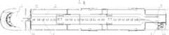
图1是本实用新型风道系统结构示意图;Fig. 1 is a structural schematic diagram of the air duct system of the present utility model;
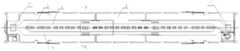
图2是图1的A向视图;Fig. 2 is the A direction view of Fig. 1;
图3是本实用新型的废排风口布置图;Fig. 3 is a layout diagram of the exhaust air outlet of the utility model;
图4是本实用新型客室车厢风道系统结构示意图;Fig. 4 is a structural schematic diagram of the air duct system in the passenger compartment of the utility model;
图5是图4的B-B剖视图。Fig. 5 is a B-B sectional view of Fig. 4 .
如图1至图5所示,客室车厢1,空调机组2,废排机组3,送风风道4,回风风道5,卫生间6,司机室7,送风口8、9、10,回风口11、12,废排风口13、14,风道出风口15,出风口16,进风口17,导流板18,静压腔19,座椅20,地板中废排风道21,车下废排风道22。As shown in Figures 1 to 5,
具体实施方式Detailed ways
下面结合附图与具体实施方式对本实用新型作进一步详细描述:Below in conjunction with accompanying drawing and specific embodiment the utility model is described in further detail:
如图1所示,一种城际动车组用空调风道系统,在每节客室车厢1设置两台单元式空调机组2和一台废排机组3。As shown in FIG. 1 , an air-conditioning duct system for an intercity EMU is provided with two unitary air-
两台空调机组2均安装于车顶,每台空调机组2均包括一个壳体,在壳体内分为室内侧和室外侧,室外侧包括压缩机、冷凝器及冷凝风机等;室内侧包括蒸发器、蒸发风机、出风口16、进风口17及新风口(图中未示出)。其中,出风口16与送风风道4连通,送风风道4与若干个车内的送风口连通,用于向客室车厢1、卫生间6、司机室7送入经过蒸发器处理后的空气,调节车内的温度、湿度及空气的新鲜度;进风口17与回风风道5连通,回风风道5与多个车内的回风口连通,用于将车内污浊的空气返回至空调机组2内,与从新风口进入的新风混合后,与蒸发器进行热交换,再送至车内,形成空气循环。Both air-
废排机组3安装于车体底部,通过废排风道与车内的废排风口连通,车内的废气经过废排机组3排出车外,废气由废排机组3排出有利于保证整车的气密性和微正压的要求。The waste exhaust unit 3 is installed at the bottom of the car body, and communicates with the waste exhaust outlet in the car through the waste exhaust duct. The exhaust gas in the car is discharged outside the vehicle through the waste exhaust unit 3. Air tightness and micro positive pressure requirements.
如图2、图4及图5所示,送风风道4和回风风道5均设置于车顶部,位于车内顶板的上方,送风风道4和回风风道5均沿车体长度方向通长设置。如图5所示,送风风道4位于中间,沿车体的中心线布置,回风风道5设置于送风风道4的两侧。本实施例中,优选,将送风风道4和回风风道5设置为一体式结构,这样,可以最大限度地减轻风道的总重量,从而满足车辆轻量化的要求。同时,本实施例中,送风风道4和回风风道5均采用铝板材料,不但可以保证送风风道4和回风风道5的强度,还可以进一步降低风道的总重量。As shown in Figure 2, Figure 4 and Figure 5, the
如图1所示,送风风道4由头车的客室车厢1一直延伸至司机室7内,司机室7内可以单独设置空调,也可以只由客室车厢1内的空调机组2提供送风,或者两种形式同时使用。送风风道4也一直延伸至卫生间6内,向卫生间6内送风。回风风道5可以延伸至司机室7内,但为了减轻重量,本实施例中,优选,在司机室7内不设置回风风道5,司机室7的回风统一由客室车厢1内的回风风道5完成。As shown in Figure 1, the
如图2和图4所示,车内的送风口包括客室车厢1内的送风口8、卫生间6的送风口9及司机室7内的送风口10。车内的回风口包括客室车厢1内的回风口11及司机室7的回风口12。如图3所示,车内的废排风口包括客室车厢1内的废排风口13及卫生间6内的废排风口14。As shown in FIGS. 2 and 4 , the air supply ports in the car include the air supply port 8 in the
其中,客室车厢1内的多个送风口8设置于送风风道4下方的客室车厢1的顶板上,沿车体的长度方向均匀设置于车厢顶板的中央区域内。如图5所示,送风风道4的底部开有若干个呈圆形的风道出风口15,在每个风道出风口15的下方设置有用于将气流分流的呈弧形的导流板18,导流板18通过螺钉固定于送风风道4的底部,送风口8均采用孔板结构,送风风道4的下表面与位于顶板上的孔板结构的送风口8之间围成向车内送风的静压腔19,有利于车内气流组织均匀,提高车厢内的舒适度。Wherein, a plurality of air supply ports 8 in the
经空调机组2送出的冷风进入车顶的送风风道4,经过多个圆形的风道出风口15和弧形的导流板18后,进入送风风道4下方的静压腔19内,再通过孔板结构的送风口8送入客室车厢1内。The cold air sent by the
如图4所示,每节客室车厢1内的回风口11为两个,分别设置于车体两端的车厢顶板上,两个回风口11与两条回风风道5连通,回风口11采用格栅结构。车内回风由车体两端的回风口11进入车顶的两条回风风道5内,这样在每个车厢1内形成中央送风,车体两端集中回风的风道系统,更进一步有利于车内气流组织均匀。As shown in Figure 4, there are two return air outlets 11 in each
如图1和图2所示,司机室7内的送风口10设置在司机室7的顶板上,头车的客室车厢1内的送风风道4延伸至司机室7内,与司机室7内的送风口10连通,送风口10与上述相同,也采用孔板结构,送风风道4的底部开有呈圆形的风道出风口15,在风道出风口15的下方设置有用于将气流分流的呈弧形的导流板18,导流板18通过螺钉固定于送风风道4的底部,送风风道4的下表面与位于顶板上的孔板结构的送风口10之间围成向司机室7内送风的静压腔19。由于司机室7的面积较小,可以在司机室7内只设置一个送风口10。As shown in Figures 1 and 2, the air outlet 10 in the driver's cab 7 is arranged on the top plate of the driver's cab 7, and the
本实施例中,由于司机室7内不设回风风道5,所以,司机室7内的回风口12设置在司机室7与客室车厢1连通的过道门20上,也可以设置在端墙上。司机室内的回风经过回风口12首先进入头车的客室车厢1内,再通过客室车厢1内的回风口11返回至回风风道5内。此处的回风口12也采用格栅结构。In this embodiment, since the
如图2和图4所示,卫生间6的送风口9同样设置在的卫生间6顶板上,送风口9采用隔栅结构。因为卫生间6的面积较小,送风口9的数量可以只设置一个,送风风道9在此处的出口直接与送风口9相连,不需要设置上述的导流板18等结构。卫生间6内的废气通过设置在卫生间6内下方的废排风口14排出。As shown in Figure 2 and Figure 4, the air supply port 9 of the toilet 6 is also arranged on the top plate of the toilet 6, and the air supply port 9 adopts a grid structure. Because the area of toilet 6 is less, the quantity of air supply port 9 can only be provided with one, and the outlet of air supply duct 9 here directly links to each other with air supply port 9, and structures such as above-mentioned
如图3所示,客室车厢1内的废排风口13设置有多个,如图5所示,废排风口13设置于客室车厢1内的座椅20下方,有利于节省车内的空间,同时利于废气的排放。As shown in Figure 3, there are multiple waste air outlets 13 in the
如图1和如图5所示,废排风道包括地板中废排风道21和车下废排风道22,地板中废排风道21的进风口穿过地板与客室车厢1内的废排风口13和卫生间6内的废排风口14连通,地板中废排风道21的出风口与车下废排风道22连通,车下废排风道22的另一端连通于废排机组3。车内的废气由废排风口13和废排风口14进入地板中废排风道21,再经由车下废排风道22进入废排机组3,最后由废排机组3排出车外。As shown in Fig. 1 and Fig. 5, the waste exhaust air duct includes the waste
通过调整空调机组2室内侧蒸发风机及废排机组3内废排内机的压头及风量,进而调节车内的回风量及废排风量,以保证车内空气的新鲜度,保证卫生间6内无异味。By adjusting the pressure head and air volume of the indoor evaporating fan of the air-
为了减轻风道的总重量,车下废排风道22采用铝板材料,地板中的废排风道21则采用玻璃钢材料,玻璃钢有较好的强度,而且重量较轻,易于加工成形。In order to reduce the total weight of the air duct, the waste
如上所述,结合附图和实施例所给出的方案内容,可以衍生出类似的技术方案。但凡是未脱离本实用新型技术方案的内容,依据本实用新型的技术实质对以上实施例所作的任何简单修改、等同变化与修饰,均仍属于本实用新型技术方案的范围内。As mentioned above, a similar technical solution can be derived in combination with the solutions presented in the drawings and the embodiments. However, any simple modifications, equivalent changes and modifications made to the above embodiments according to the technical essence of the present utility model without departing from the content of the technical solution of the utility model still belong to the scope of the technical solution of the utility model.
Claims (10)
Priority Applications (1)
| Application Number | Priority Date | Filing Date | Title |
|---|---|---|---|
| CN2011205101250UCN202378885U (en) | 2011-12-09 | 2011-12-09 | Air conditioning air duct system for intercity motor train unit |
Applications Claiming Priority (1)
| Application Number | Priority Date | Filing Date | Title |
|---|---|---|---|
| CN2011205101250UCN202378885U (en) | 2011-12-09 | 2011-12-09 | Air conditioning air duct system for intercity motor train unit |
Publications (1)
| Publication Number | Publication Date |
|---|---|
| CN202378885Utrue CN202378885U (en) | 2012-08-15 |
Family
ID=46627403
Family Applications (1)
| Application Number | Title | Priority Date | Filing Date |
|---|---|---|---|
| CN2011205101250UExpired - LifetimeCN202378885U (en) | 2011-12-09 | 2011-12-09 | Air conditioning air duct system for intercity motor train unit |
Country Status (1)
| Country | Link |
|---|---|
| CN (1) | CN202378885U (en) |
Cited By (10)
| Publication number | Priority date | Publication date | Assignee | Title |
|---|---|---|---|---|
| CN103158730A (en)* | 2011-12-09 | 2013-06-19 | 南车青岛四方机车车辆股份有限公司 | Air-conditioner air duct system used for intercity motor train unit |
| CN103496375A (en)* | 2013-09-27 | 2014-01-08 | 无锡金鑫集团股份有限公司 | Air conditioner air duct of CRH3-380 high-speed motor train unit |
| CN103661458A (en)* | 2013-12-17 | 2014-03-26 | 南车青岛四方机车车辆股份有限公司 | Air-conditioner unit air duct system for vehicle |
| CN104228863A (en)* | 2014-09-22 | 2014-12-24 | 南车南京浦镇车辆有限公司 | Railway-vehicle air-conditioner air supplying and returning system |
| CN104554313A (en)* | 2015-01-12 | 2015-04-29 | 南车青岛四方机车车辆股份有限公司 | Ultra-thin air conditioning unit and urban rail vehicle installed with air conditioning unit |
| CN104554314A (en)* | 2015-01-12 | 2015-04-29 | 南车青岛四方机车车辆股份有限公司 | Urban rail vehicle air conditioning and ventilation system and urban rail vehicle |
| CN106347394A (en)* | 2016-09-07 | 2017-01-25 | 中车唐山机车车辆有限公司 | Air duct system of sleeping berth motor train unit |
| CN109435994A (en)* | 2018-11-09 | 2019-03-08 | 中车长春轨道客车股份有限公司 | A kind of track train gives up heat-extraction system and the track train with the heat-extraction system that gives up |
| WO2020206835A1 (en)* | 2019-04-10 | 2020-10-15 | 中车唐山机车车辆有限公司 | Rail train |
| CN112849181A (en)* | 2021-03-12 | 2021-05-28 | 中车唐山机车车辆有限公司 | Air supply system and multi-layer railway vehicle |
- 2011
- 2011-12-09CNCN2011205101250Upatent/CN202378885U/ennot_activeExpired - Lifetime
Cited By (12)
| Publication number | Priority date | Publication date | Assignee | Title |
|---|---|---|---|---|
| CN103158730A (en)* | 2011-12-09 | 2013-06-19 | 南车青岛四方机车车辆股份有限公司 | Air-conditioner air duct system used for intercity motor train unit |
| CN103496375A (en)* | 2013-09-27 | 2014-01-08 | 无锡金鑫集团股份有限公司 | Air conditioner air duct of CRH3-380 high-speed motor train unit |
| CN103661458A (en)* | 2013-12-17 | 2014-03-26 | 南车青岛四方机车车辆股份有限公司 | Air-conditioner unit air duct system for vehicle |
| CN103661458B (en)* | 2013-12-17 | 2017-02-01 | 中车青岛四方机车车辆股份有限公司 | Air-conditioner unit air duct system for vehicle |
| CN104228863A (en)* | 2014-09-22 | 2014-12-24 | 南车南京浦镇车辆有限公司 | Railway-vehicle air-conditioner air supplying and returning system |
| CN104554313A (en)* | 2015-01-12 | 2015-04-29 | 南车青岛四方机车车辆股份有限公司 | Ultra-thin air conditioning unit and urban rail vehicle installed with air conditioning unit |
| CN104554314A (en)* | 2015-01-12 | 2015-04-29 | 南车青岛四方机车车辆股份有限公司 | Urban rail vehicle air conditioning and ventilation system and urban rail vehicle |
| CN104554314B (en)* | 2015-01-12 | 2017-05-24 | 中车青岛四方机车车辆股份有限公司 | Urban rail vehicle air conditioning and ventilation system and urban rail vehicle |
| CN106347394A (en)* | 2016-09-07 | 2017-01-25 | 中车唐山机车车辆有限公司 | Air duct system of sleeping berth motor train unit |
| CN109435994A (en)* | 2018-11-09 | 2019-03-08 | 中车长春轨道客车股份有限公司 | A kind of track train gives up heat-extraction system and the track train with the heat-extraction system that gives up |
| WO2020206835A1 (en)* | 2019-04-10 | 2020-10-15 | 中车唐山机车车辆有限公司 | Rail train |
| CN112849181A (en)* | 2021-03-12 | 2021-05-28 | 中车唐山机车车辆有限公司 | Air supply system and multi-layer railway vehicle |
Similar Documents
| Publication | Publication Date | Title |
|---|---|---|
| CN202378885U (en) | Air conditioning air duct system for intercity motor train unit | |
| CN103158730B (en) | Intercity motor train unit air conditioning duct system | |
| CN105946884B (en) | A kind of vehicle supply air system | |
| CN103373366B (en) | Air conditioner of subway vehicle unit ventilation system | |
| CN202213585U (en) | Air conditioning ventilation system of high-speed railway vehicle | |
| CN101850774B (en) | Air conditioning duct system of high speed sleeper | |
| CN204279454U (en) | A kind of speed motor train unit air conditioner ventilation system | |
| CN103625491B (en) | There is the roof-mounted air-condition unit of active pressure defencive function | |
| CN107757642B (en) | Highly integrated multifunctional cab air-conditioning ventilation system | |
| CN111361582B (en) | Low-noise air conditioner air duct for railway vehicle | |
| CN103661458B (en) | Air-conditioner unit air duct system for vehicle | |
| CN103158732B (en) | Speed motor train unit air conditioner ducting system | |
| CN111976766A (en) | Air conditioner air duct for rail transit vehicle | |
| CN104228863A (en) | Railway-vehicle air-conditioner air supplying and returning system | |
| CN107310566A (en) | Air channel structure and the vehicle with it | |
| CN202413811U (en) | Air-conditioning air duct system for high-speed motor train unit | |
| WO2022257445A1 (en) | Roof structure of railway vehicle | |
| CN114735038A (en) | Rail Passenger Car Air Conditioning Comfort Temperature Epidemic Prevention and Energy Saving Return Air System | |
| CN205652132U (en) | Air conditioner air duct system of vehicle and have its vehicle | |
| CN204095825U (en) | Railway vehicle air conditioner return air blowing system | |
| CN201400185Y (en) | High-speed sleeper train air conditioning duct system | |
| CN103434522A (en) | Railway compartment exhaust emission device | |
| CN208053040U (en) | Heat pump air conditioner for electric vehicle | |
| CN203439042U (en) | Rail compartment waste discharge device | |
| CN201272356Y (en) | Air conditioning duct system of rail vehicle |
Legal Events
| Date | Code | Title | Description |
|---|---|---|---|
| C14 | Grant of patent or utility model | ||
| GR01 | Patent grant | ||
| C56 | Change in the name or address of the patentee | ||
| CP01 | Change in the name or title of a patent holder | Address after:Jihongtan town Chengyang District Shandong city Qingdao province Jinhong road 266111 No. 88 Patentee after:CRRC QINGDAO SIFANG CO., LTD. Address before:Jihongtan town Chengyang District Shandong city Qingdao province Jinhong road 266111 No. 88 Patentee before:CSR Qingdao Sifang Locomotive and Rolling Stock Co., Ltd. | |
| CX01 | Expiry of patent term | ||
| CX01 | Expiry of patent term | Granted publication date:20120815 |