CN202290828U - One-step forming die for gear shaft - Google Patents
One-step forming die for gear shaftDownload PDFInfo
- Publication number
- CN202290828U CN202290828UCN2011203537941UCN201120353794UCN202290828UCN 202290828 UCN202290828 UCN 202290828UCN 2011203537941 UCN2011203537941 UCN 2011203537941UCN 201120353794 UCN201120353794 UCN 201120353794UCN 202290828 UCN202290828 UCN 202290828U
- Authority
- CN
- China
- Prior art keywords
- die
- forming die
- punch
- gear
- gear shaft
- Prior art date
- Legal status (The legal status is an assumption and is not a legal conclusion. Google has not performed a legal analysis and makes no representation as to the accuracy of the status listed.)
- Expired - Fee Related
Links
Images

Landscapes
- Forging (AREA)
Abstract
Description
Translated fromChinese技术领域technical field
本实用新型涉及机械加工模具领域,具体是一种齿轮轴一次成形模具。 The utility model relates to the field of mechanical processing moulds, in particular to a gear shaft forming mould. the
背景技术Background technique
齿轮轴的加工是机械加工的难点,加工的对象不仅齿轮齿面加工困难,同时由于齿形与齿轮轴其它部分技术要求高,因而加工难度大。 The processing of the gear shaft is a difficult point in mechanical processing. The object to be processed is not only difficult to process the gear tooth surface, but also due to the high technical requirements for the tooth shape and other parts of the gear shaft, the processing is difficult. the
现有采用的加工方法是:齿面采用滚齿机加工、传递动力四方用铣加工。这种加工方式的缺点是:效率低;毛刺大,去除毛刺困难,产品合格率低,而且加工工作量大。 The existing processing methods are as follows: the tooth surface is processed by gear hobbing machine, and the power transmission square is processed by milling. The disadvantages of this processing method are: low efficiency; large burrs, difficult to remove burrs, low product qualification rate, and heavy processing workload. the
发明内容Contents of the invention
本实用新型的目的是提供一种齿轮轴一次成形模具,用以改进上述工艺,具体通过以下技术方案实现: The purpose of this utility model is to provide a gear shaft one-time forming die to improve the above-mentioned process, which is specifically realized through the following technical solutions:
一种齿轮轴一次成形模具,该成型模具包括模架、下模固定套、四方成型凹模、凹模压圈、齿轮成型凹模、凸模、固定螺母、衬套、凸模固定套、顶杆;下模固定套设置在模架下部;凹模压圈内自上而下依次装有齿轮成型凹模和四方成型凹模并设置在下模固定套内;凸模通过固定螺母、衬套与凸模固定套设置在模架上部且凸模与齿轮成型凹模同轴;用来使加工件脱模的顶杆设置在模架底部并且与四方成型凹模同轴。A gear shaft one-time forming mold, the forming mold includes a mold base, a lower mold fixing sleeve, a square forming die, a die pressure ring, a gear forming die, a punch, a fixing nut, a bushing, a punch fixing sleeve, and a push rod The lower mold fixing sleeve is set at the lower part of the mold base; the gear forming die and the square forming die are sequentially installed in the die pressing ring from top to bottom and are arranged in the lower mold fixing sleeve; the punch passes through the fixing nut, the bushing and the punch The fixed sleeve is arranged on the upper part of the formwork and the punch is coaxial with the gear forming die; the ejector pin used to demould the workpiece is arranged at the bottom of the formwork and is coaxial with the square forming die.
所述的一种具有齿轮轴一次成形模具,其进一步设计在于:所述下模固定套上还设有用来调整齿轮成型凹模与凸模同轴度的调整螺栓。 The above-mentioned one-time forming die with gear shaft is further designed in that: the fixed sleeve of the lower die is also provided with an adjusting bolt for adjusting the coaxiality of the gear forming concave die and the male die. the
所述的一种具有齿轮轴一次成形模具,其进一步设计在于:所述凸模与模架上端之间设有垫板。 The above-mentioned one-time forming mold with a gear shaft is further designed in that: a backing plate is provided between the punch and the upper end of the mold frame. the
本实用新型采用了齿轮轴一次成形的模具结构,与现有技术相比,它的优点是:本实用新型的凸模与凹模结构优化,凸模、凹模的强度得到了提高,延长了模具的使用寿命;本实用新型采用了特殊的模具结构,使传递动力四方与齿形一次成形,保证了工件质量要求,提高了生产效率,降低了生产成本;本实用新型结构巧妙,更换方便。 The utility model adopts a mold structure for one-time forming of the gear shaft. Compared with the prior art, its advantages are: the structure of the punch and the die of the utility model is optimized, the strength of the punch and the die is improved, and the The service life of the mold; the utility model adopts a special mold structure, which makes the transmission power square and the tooth shape form at one time, which ensures the quality requirements of the workpiece, improves the production efficiency, and reduces the production cost; the utility model has an ingenious structure and is easy to replace. the
附图说明Description of drawings
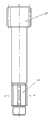
图1是本实用新型的结构示意图。 Fig. 1 is the structural representation of the utility model. the
图2是本实用新型所述齿轮轴结构示意图。 Fig. 2 is a schematic diagram of the structure of the gear shaft of the present invention. the
图3是图2中A-A截面视图。 Fig. 3 is a sectional view of A-A in Fig. 2 . the
具体实施方式Detailed ways
如图1所示的成形模具,包括模架1、下模固定套2、四方成型凹模3、凹模压圈4、齿轮成型凹模5、压板6、凸模7、固定螺母8、衬套9、凸模固定套10、垫板11和顶杆12;下模固定套2设置在模架1下部;凹模压圈4内装有四方成型凹模3和齿轮成型凹模5并固定在下模固定套2内;凸模7通过固定螺母8与凸模固定套10固定在模架1上部,并由衬套10定位在与齿轮成型凹模5相对应的位置;模架1底部中央设有通孔,顶杆12通过一螺母以及该通孔设置在模架1底部中央,设置在模架1上并位于四方成型凹模3的下端。下模固定套2上还设有用来调整齿轮成型凹模5与凸模7同轴度的调整螺栓13。凸模7与模架1上端之间设有用于保证凸模7平稳下移的垫板11。 The forming mold shown in Figure 1 includes mold base 1, lower mold fixing sleeve 2, square forming die 3, die pressure ring 4, gear forming die 5, pressing plate 6, punch 7, fixing nut 8, bushing 9. Punch fixed sleeve 10, backing plate 11 and ejector rod 12; lower mold fixed sleeve 2 is set at the lower part of mold frame 1; die ring 4 is equipped with square forming die 3 and gear forming die 5 and fixed on the lower die The punch 7 is fixed on the upper part of the mold base 1 through the fixing nut 8 and the punch fixing sleeve 10, and is positioned at the position corresponding to the gear forming die 5 by the bushing 10; the bottom center of the mold base 1 is equipped with a Hole, push rod 12 is arranged on the bottom center of formwork 1 through a nut and this through hole, is arranged on formwork 1 and is positioned at the lower end of quadrangular forming die 3. The lower die fixing sleeve 2 is also provided with an adjusting bolt 13 for adjusting the coaxiality of the gear forming die 5 and the punch 7 . A backing plate 11 for ensuring the smooth downward movement of the punch 7 is provided between the punch 7 and the upper end of the mold frame 1 . the
挤压时,首先将挤压毛坯放在齿轮成型凹模5内,凸模7下行,将挤压毛坯同时挤入四方成型凹模3和齿轮成型凹模5内,使传递动力四方和齿轮一次成形。当固定螺母8端面与凹模压圈4端面接触时,凸模7不能下行,挤压结束。顶杆12上行,将工件从凹模中顶出,对照图2以及图3,齿轮轴的齿轮部分15在齿轮成型凹模5挤压成型,齿轮轴的四方部分16在四方成型凹模3中挤压成型。 When extruding, first put the extrusion blank in the gear forming die 5, and the punch 7 goes down, and squeeze the extrusion blank into the square forming die 3 and the gear forming die 5 at the same time, so that the transmission power of the square and the gear is once take shape. When the end face of the fixed nut 8 is in contact with the end face of the die pressure ring 4, the punch 7 cannot descend, and the extrusion ends. The ejector rod 12 goes up to eject the workpiece from the die. Referring to Fig. 2 and Fig. 3, the
为保护凸模7,采用了导柱与导套作导向四导柱模架1。为保护齿轮成型凹模5,在模具结构上采取了限位措施。本实用新型凸模更换方便。本实用新型使传递动力四方与齿形一次成形,保证了工件质量要求,提高了生产效率,降低了生产成本。 For protecting punch 7, adopted guide post and guide sleeve as guiding four guide post formwork 1. In order to protect the gear forming die 5, position-limiting measures are taken on the mold structure. The punch of the utility model is convenient to replace. The utility model makes the transmission power square and the tooth shape form at one time, which ensures the quality requirements of the workpiece, improves the production efficiency and reduces the production cost. the
Claims (3)
Priority Applications (1)
| Application Number | Priority Date | Filing Date | Title |
|---|---|---|---|
| CN2011203537941UCN202290828U (en) | 2011-09-21 | 2011-09-21 | One-step forming die for gear shaft |
Applications Claiming Priority (1)
| Application Number | Priority Date | Filing Date | Title |
|---|---|---|---|
| CN2011203537941UCN202290828U (en) | 2011-09-21 | 2011-09-21 | One-step forming die for gear shaft |
Publications (1)
| Publication Number | Publication Date |
|---|---|
| CN202290828Utrue CN202290828U (en) | 2012-07-04 |
Family
ID=46359809
Family Applications (1)
| Application Number | Title | Priority Date | Filing Date |
|---|---|---|---|
| CN2011203537941UExpired - Fee RelatedCN202290828U (en) | 2011-09-21 | 2011-09-21 | One-step forming die for gear shaft |
Country Status (1)
| Country | Link |
|---|---|
| CN (1) | CN202290828U (en) |
Cited By (11)
| Publication number | Priority date | Publication date | Assignee | Title |
|---|---|---|---|---|
| CN102303059A (en)* | 2011-09-21 | 2012-01-04 | 南京工业职业技术学院 | One-time molding method of gear wheel shaft |
| CN102794327A (en)* | 2012-08-23 | 2012-11-28 | 湖南天雁机械有限责任公司 | Mold for extrusion forming of engine valve rotating mechanism base |
| CN103639222A (en)* | 2013-11-25 | 2014-03-19 | 梧州恒声电子科技有限公司 | U iron extrusion die |
| CN103639292A (en)* | 2013-11-25 | 2014-03-19 | 梧州恒声电子科技有限公司 | Lower die structure of U-iron extrusion die |
| CN103752639A (en)* | 2014-01-26 | 2014-04-30 | 无锡市神力齿轮冷挤有限公司 | Cold extrusion die for output shaft of starter |
| CN104084489A (en)* | 2014-06-26 | 2014-10-08 | 梧州恒声电子科技有限公司 | Die fine adjusting mechanism |
| CN104259237A (en)* | 2014-09-26 | 2015-01-07 | 北京北方车辆集团有限公司 | Hot extrusion die applicable to extrusion and forming of inner hexagonal bolt of track end coupling device |
| CN105834238A (en)* | 2016-05-30 | 2016-08-10 | 南京工业职业技术学院 | Stopper ring molding and shaping mold and stopper ring production method |
| CN107716727A (en)* | 2017-11-29 | 2018-02-23 | 中国航空工业标准件制造有限责任公司 | Punch process supporting plate self-lock nut pallet flute profile shaping mould |
| CN108246962A (en)* | 2017-11-27 | 2018-07-06 | 苏州麦德柯金属制品工业有限公司 | The processing technology and its processing mold of a kind of rivet |
| CN111266430A (en)* | 2018-12-04 | 2020-06-12 | 无锡市华机机械制造有限公司 | Method for forming rotating shaft for pneumatic actuator |
- 2011
- 2011-09-21CNCN2011203537941Upatent/CN202290828U/ennot_activeExpired - Fee Related
Cited By (13)
| Publication number | Priority date | Publication date | Assignee | Title |
|---|---|---|---|---|
| CN102303059A (en)* | 2011-09-21 | 2012-01-04 | 南京工业职业技术学院 | One-time molding method of gear wheel shaft |
| CN102794327B (en)* | 2012-08-23 | 2016-06-29 | 湖南天雁机械有限责任公司 | Engine valve rotating mechanism base extrusion forming mold |
| CN102794327A (en)* | 2012-08-23 | 2012-11-28 | 湖南天雁机械有限责任公司 | Mold for extrusion forming of engine valve rotating mechanism base |
| CN103639222A (en)* | 2013-11-25 | 2014-03-19 | 梧州恒声电子科技有限公司 | U iron extrusion die |
| CN103639292A (en)* | 2013-11-25 | 2014-03-19 | 梧州恒声电子科技有限公司 | Lower die structure of U-iron extrusion die |
| CN103752639B (en)* | 2014-01-26 | 2016-08-17 | 无锡市神力齿轮冷挤有限公司 | Starter motor output shaft cold extrusion die |
| CN103752639A (en)* | 2014-01-26 | 2014-04-30 | 无锡市神力齿轮冷挤有限公司 | Cold extrusion die for output shaft of starter |
| CN104084489A (en)* | 2014-06-26 | 2014-10-08 | 梧州恒声电子科技有限公司 | Die fine adjusting mechanism |
| CN104259237A (en)* | 2014-09-26 | 2015-01-07 | 北京北方车辆集团有限公司 | Hot extrusion die applicable to extrusion and forming of inner hexagonal bolt of track end coupling device |
| CN105834238A (en)* | 2016-05-30 | 2016-08-10 | 南京工业职业技术学院 | Stopper ring molding and shaping mold and stopper ring production method |
| CN108246962A (en)* | 2017-11-27 | 2018-07-06 | 苏州麦德柯金属制品工业有限公司 | The processing technology and its processing mold of a kind of rivet |
| CN107716727A (en)* | 2017-11-29 | 2018-02-23 | 中国航空工业标准件制造有限责任公司 | Punch process supporting plate self-lock nut pallet flute profile shaping mould |
| CN111266430A (en)* | 2018-12-04 | 2020-06-12 | 无锡市华机机械制造有限公司 | Method for forming rotating shaft for pneumatic actuator |
Similar Documents
| Publication | Publication Date | Title |
|---|---|---|
| CN202290828U (en) | One-step forming die for gear shaft | |
| CN101767153B (en) | A compound forming mold | |
| CN103894581B (en) | A kind of die casting for manufacturing air blade | |
| CN203003032U (en) | Precision forging extrusion die device | |
| CN103230950A (en) | Spline gear cold extrusion one-step molding device | |
| CN102303059A (en) | One-time molding method of gear wheel shaft | |
| CN103551851B (en) | A kind of sheet metal part combined shaping method of bottom belt bulge-structure and mould | |
| CN201566151U (en) | Powder molding hydrodynamic press | |
| CN201008901Y (en) | One-time forming die for step gear with special-shaped hole | |
| CN201960038U (en) | Deep drawing die for producing bowl-shaped ornaments | |
| CN105834238A (en) | Stopper ring molding and shaping mold and stopper ring production method | |
| CN206632201U (en) | A kind of counter sink press forming die | |
| CN202343710U (en) | Compound die mechanism for blanking and drawing | |
| CN110014126B (en) | Convenient ejecting ring flange mould | |
| CN111300766A (en) | A mould for producing vapour vehicle support | |
| CN203862945U (en) | Forging ring combination die | |
| CN103230956A (en) | Cold extrusion device for gear of starting motor of engine | |
| CN204320831U (en) | A kind of cold extrusion die | |
| CN203265507U (en) | Bi-directional spinning mould for forging loader wheel | |
| CN209439309U (en) | A kind of automobile drawing type stamping die for high-tension plates | |
| CN210059801U (en) | Iron-based powder die for manufacturing eccentric ratchet wheel with shifting pin and metallurgical device | |
| CN201693015U (en) | Double-head pipe joint cold extrusion mold | |
| CN206335035U (en) | One-stop drawing blanking die | |
| CN203076356U (en) | Cold extrusion mould | |
| CN205201979U (en) | Injection mould of gland |
Legal Events
| Date | Code | Title | Description |
|---|---|---|---|
| C14 | Grant of patent or utility model | ||
| GR01 | Patent grant | ||
| CF01 | Termination of patent right due to non-payment of annual fee | Granted publication date:20120704 Termination date:20140921 | |
| EXPY | Termination of patent right or utility model |