CN202225179U - Power tool and power tool system - Google Patents
Power tool and power tool systemDownload PDFInfo
- Publication number
- CN202225179U CN202225179UCN2011200997869UCN201120099786UCN202225179UCN 202225179 UCN202225179 UCN 202225179UCN 2011200997869 UCN2011200997869 UCN 2011200997869UCN 201120099786 UCN201120099786 UCN 201120099786UCN 202225179 UCN202225179 UCN 202225179U
- Authority
- CN
- China
- Prior art keywords
- voltage
- battery
- temperature
- electric power
- parts
- Prior art date
- Legal status (The legal status is an assumption and is not a legal conclusion. Google has not performed a legal analysis and makes no representation as to the accuracy of the status listed.)
- Expired - Fee Related
Links
- 230000004044responseEffects0.000claimsabstractdescription3
- 238000005259measurementMethods0.000claimsdescription41
- 238000012544monitoring processMethods0.000claimsdescription16
- 230000001052transient effectEffects0.000claimsdescription2
- 238000013016dampingMethods0.000claims4
- 230000003313weakening effectEffects0.000abstract1
- 238000000034methodMethods0.000description41
- 238000007599dischargingMethods0.000description11
- 229910001416lithium ionInorganic materials0.000description10
- HBBGRARXTFLTSG-UHFFFAOYSA-NLithium ionChemical compound[Li+]HBBGRARXTFLTSG-UHFFFAOYSA-N0.000description6
- 238000005516engineering processMethods0.000description6
- 230000006870functionEffects0.000description5
- ZCJJIQHVZCFSGZ-UHFFFAOYSA-N2,8-bis(diphenylphosphoryl)dibenzothiopheneChemical compoundC=1C=CC=CC=1P(C=1C=C2C3=CC(=CC=C3SC2=CC=1)P(=O)(C=1C=CC=CC=1)C=1C=CC=CC=1)(=O)C1=CC=CC=C1ZCJJIQHVZCFSGZ-UHFFFAOYSA-N0.000description3
- 229910005580NiCdInorganic materials0.000description3
- 230000002441reversible effectEffects0.000description3
- 239000000126substanceSubstances0.000description3
- 239000002253acidSubstances0.000description2
- 230000000712assemblyEffects0.000description2
- 238000000429assemblyMethods0.000description2
- 238000010586diagramMethods0.000description2
- 230000005059dormancyEffects0.000description2
- 238000000605extractionMethods0.000description2
- 229910052744lithiumInorganic materials0.000description2
- 230000000737periodic effectEffects0.000description2
- WHXSMMKQMYFTQS-UHFFFAOYSA-NLithiumChemical compound[Li]WHXSMMKQMYFTQS-UHFFFAOYSA-N0.000description1
- 230000002411adverseEffects0.000description1
- 238000006243chemical reactionMethods0.000description1
- 230000007423decreaseEffects0.000description1
- 238000013461designMethods0.000description1
- 238000001514detection methodMethods0.000description1
- 238000005553drillingMethods0.000description1
- 230000000694effectsEffects0.000description1
- 230000005611electricityEffects0.000description1
- 239000000284extractSubstances0.000description1
- 229910052739hydrogenInorganic materials0.000description1
- 239000001257hydrogenSubstances0.000description1
- 238000002955isolationMethods0.000description1
- 239000003550markerSubstances0.000description1
- 229910052987metal hydrideInorganic materials0.000description1
- 238000012986modificationMethods0.000description1
- 230000004048modificationEffects0.000description1
- 229910052759nickelInorganic materials0.000description1
- PXHVJJICTQNCMI-UHFFFAOYSA-NnickelSubstances[Ni]PXHVJJICTQNCMI-UHFFFAOYSA-N0.000description1
- -1nickel metal hydrideChemical class0.000description1
- 229920000642polymerPolymers0.000description1
- 230000002035prolonged effectEffects0.000description1
- 238000012958reprocessingMethods0.000description1
- 238000005070samplingMethods0.000description1
- 238000000926separation methodMethods0.000description1
- 238000012360testing methodMethods0.000description1
Images


Classifications
- H—ELECTRICITY
- H02—GENERATION; CONVERSION OR DISTRIBUTION OF ELECTRIC POWER
- H02P—CONTROL OR REGULATION OF ELECTRIC MOTORS, ELECTRIC GENERATORS OR DYNAMO-ELECTRIC CONVERTERS; CONTROLLING TRANSFORMERS, REACTORS OR CHOKE COILS
- H02P7/00—Arrangements for regulating or controlling the speed or torque of electric DC motors
- H02P7/06—Arrangements for regulating or controlling the speed or torque of electric DC motors for regulating or controlling an individual DC dynamo-electric motor by varying field or armature current
- H02P7/18—Arrangements for regulating or controlling the speed or torque of electric DC motors for regulating or controlling an individual DC dynamo-electric motor by varying field or armature current by master control with auxiliary power
- H02P7/24—Arrangements for regulating or controlling the speed or torque of electric DC motors for regulating or controlling an individual DC dynamo-electric motor by varying field or armature current by master control with auxiliary power using discharge tubes or semiconductor devices
- H02P7/28—Arrangements for regulating or controlling the speed or torque of electric DC motors for regulating or controlling an individual DC dynamo-electric motor by varying field or armature current by master control with auxiliary power using discharge tubes or semiconductor devices using semiconductor devices
- H02P7/285—Arrangements for regulating or controlling the speed or torque of electric DC motors for regulating or controlling an individual DC dynamo-electric motor by varying field or armature current by master control with auxiliary power using discharge tubes or semiconductor devices using semiconductor devices controlling armature supply only
- H02P7/29—Arrangements for regulating or controlling the speed or torque of electric DC motors for regulating or controlling an individual DC dynamo-electric motor by varying field or armature current by master control with auxiliary power using discharge tubes or semiconductor devices using semiconductor devices controlling armature supply only using pulse modulation
- B—PERFORMING OPERATIONS; TRANSPORTING
- B25—HAND TOOLS; PORTABLE POWER-DRIVEN TOOLS; MANIPULATORS
- B25F—COMBINATION OR MULTI-PURPOSE TOOLS NOT OTHERWISE PROVIDED FOR; DETAILS OR COMPONENTS OF PORTABLE POWER-DRIVEN TOOLS NOT PARTICULARLY RELATED TO THE OPERATIONS PERFORMED AND NOT OTHERWISE PROVIDED FOR
- B25F5/00—Details or components of portable power-driven tools not particularly related to the operations performed and not otherwise provided for
- B25F5/02—Construction of casings, bodies or handles
- B25F5/021—Construction of casings, bodies or handles with guiding devices
- G—PHYSICS
- G01—MEASURING; TESTING
- G01R—MEASURING ELECTRIC VARIABLES; MEASURING MAGNETIC VARIABLES
- G01R31/00—Arrangements for testing electric properties; Arrangements for locating electric faults; Arrangements for electrical testing characterised by what is being tested not provided for elsewhere
- G01R31/36—Arrangements for testing, measuring or monitoring the electrical condition of accumulators or electric batteries, e.g. capacity or state of charge [SoC]
- G01R31/374—Arrangements for testing, measuring or monitoring the electrical condition of accumulators or electric batteries, e.g. capacity or state of charge [SoC] with means for correcting the measurement for temperature or ageing
- G—PHYSICS
- G01—MEASURING; TESTING
- G01R—MEASURING ELECTRIC VARIABLES; MEASURING MAGNETIC VARIABLES
- G01R31/00—Arrangements for testing electric properties; Arrangements for locating electric faults; Arrangements for electrical testing characterised by what is being tested not provided for elsewhere
- G01R31/36—Arrangements for testing, measuring or monitoring the electrical condition of accumulators or electric batteries, e.g. capacity or state of charge [SoC]
- G01R31/382—Arrangements for monitoring battery or accumulator variables, e.g. SoC
- G01R31/3835—Arrangements for monitoring battery or accumulator variables, e.g. SoC involving only voltage measurements
- G—PHYSICS
- G01—MEASURING; TESTING
- G01R—MEASURING ELECTRIC VARIABLES; MEASURING MAGNETIC VARIABLES
- G01R31/00—Arrangements for testing electric properties; Arrangements for locating electric faults; Arrangements for electrical testing characterised by what is being tested not provided for elsewhere
- G01R31/36—Arrangements for testing, measuring or monitoring the electrical condition of accumulators or electric batteries, e.g. capacity or state of charge [SoC]
- G01R31/385—Arrangements for measuring battery or accumulator variables
- H—ELECTRICITY
- H01—ELECTRIC ELEMENTS
- H01H—ELECTRIC SWITCHES; RELAYS; SELECTORS; EMERGENCY PROTECTIVE DEVICES
- H01H9/00—Details of switching devices, not covered by groups H01H1/00 - H01H7/00
- H01H9/02—Bases, casings, or covers
- H01H9/06—Casing of switch constituted by a handle serving a purpose other than the actuation of the switch, e.g. by the handle of a vacuum cleaner
- H01H9/061—Casing of switch constituted by a handle serving a purpose other than the actuation of the switch, e.g. by the handle of a vacuum cleaner enclosing a continuously variable impedance
- H—ELECTRICITY
- H01—ELECTRIC ELEMENTS
- H01M—PROCESSES OR MEANS, e.g. BATTERIES, FOR THE DIRECT CONVERSION OF CHEMICAL ENERGY INTO ELECTRICAL ENERGY
- H01M10/00—Secondary cells; Manufacture thereof
- H01M10/42—Methods or arrangements for servicing or maintenance of secondary cells or secondary half-cells
- H01M10/44—Methods for charging or discharging
- H01M10/441—Methods for charging or discharging for several batteries or cells simultaneously or sequentially
- H—ELECTRICITY
- H01—ELECTRIC ELEMENTS
- H01R—ELECTRICALLY-CONDUCTIVE CONNECTIONS; STRUCTURAL ASSOCIATIONS OF A PLURALITY OF MUTUALLY-INSULATED ELECTRICAL CONNECTING ELEMENTS; COUPLING DEVICES; CURRENT COLLECTORS
- H01R12/00—Structural associations of a plurality of mutually-insulated electrical connecting elements, specially adapted for printed circuits, e.g. printed circuit boards [PCB], flat or ribbon cables, or like generally planar structures, e.g. terminal strips, terminal blocks; Coupling devices specially adapted for printed circuits, flat or ribbon cables, or like generally planar structures; Terminals specially adapted for contact with, or insertion into, printed circuits, flat or ribbon cables, or like generally planar structures
- H01R12/70—Coupling devices
- H01R12/7005—Guiding, mounting, polarizing or locking means; Extractors
- H—ELECTRICITY
- H01—ELECTRIC ELEMENTS
- H01R—ELECTRICALLY-CONDUCTIVE CONNECTIONS; STRUCTURAL ASSOCIATIONS OF A PLURALITY OF MUTUALLY-INSULATED ELECTRICAL CONNECTING ELEMENTS; COUPLING DEVICES; CURRENT COLLECTORS
- H01R13/00—Details of coupling devices of the kinds covered by groups H01R12/70 or H01R24/00 - H01R33/00
- H01R13/02—Contact members
- H01R13/10—Sockets for co-operation with pins or blades
- H01R13/11—Resilient sockets
- H01R13/112—Resilient sockets forked sockets having two legs
- H—ELECTRICITY
- H02—GENERATION; CONVERSION OR DISTRIBUTION OF ELECTRIC POWER
- H02J—CIRCUIT ARRANGEMENTS OR SYSTEMS FOR SUPPLYING OR DISTRIBUTING ELECTRIC POWER; SYSTEMS FOR STORING ELECTRIC ENERGY
- H02J7/00—Circuit arrangements for charging or depolarising batteries or for supplying loads from batteries
- H02J7/00032—Circuit arrangements for charging or depolarising batteries or for supplying loads from batteries characterised by data exchange
- H02J7/00034—Charger exchanging data with an electronic device, i.e. telephone, whose internal battery is under charge
- H—ELECTRICITY
- H02—GENERATION; CONVERSION OR DISTRIBUTION OF ELECTRIC POWER
- H02J—CIRCUIT ARRANGEMENTS OR SYSTEMS FOR SUPPLYING OR DISTRIBUTING ELECTRIC POWER; SYSTEMS FOR STORING ELECTRIC ENERGY
- H02J7/00—Circuit arrangements for charging or depolarising batteries or for supplying loads from batteries
- H02J7/00032—Circuit arrangements for charging or depolarising batteries or for supplying loads from batteries characterised by data exchange
- H02J7/00038—Circuit arrangements for charging or depolarising batteries or for supplying loads from batteries characterised by data exchange using passive battery identification means, e.g. resistors or capacitors
- H02J7/00041—Circuit arrangements for charging or depolarising batteries or for supplying loads from batteries characterised by data exchange using passive battery identification means, e.g. resistors or capacitors in response to measured battery parameters, e.g. voltage, current or temperature profile
- H—ELECTRICITY
- H02—GENERATION; CONVERSION OR DISTRIBUTION OF ELECTRIC POWER
- H02J—CIRCUIT ARRANGEMENTS OR SYSTEMS FOR SUPPLYING OR DISTRIBUTING ELECTRIC POWER; SYSTEMS FOR STORING ELECTRIC ENERGY
- H02J7/00—Circuit arrangements for charging or depolarising batteries or for supplying loads from batteries
- H02J7/0013—Circuit arrangements for charging or depolarising batteries or for supplying loads from batteries acting upon several batteries simultaneously or sequentially
- H02J7/0014—Circuits for equalisation of charge between batteries
- H02J7/0019—Circuits for equalisation of charge between batteries using switched or multiplexed charge circuits
- H—ELECTRICITY
- H02—GENERATION; CONVERSION OR DISTRIBUTION OF ELECTRIC POWER
- H02J—CIRCUIT ARRANGEMENTS OR SYSTEMS FOR SUPPLYING OR DISTRIBUTING ELECTRIC POWER; SYSTEMS FOR STORING ELECTRIC ENERGY
- H02J7/00—Circuit arrangements for charging or depolarising batteries or for supplying loads from batteries
- H02J7/0029—Circuit arrangements for charging or depolarising batteries or for supplying loads from batteries with safety or protection devices or circuits
- H02J7/0031—Circuit arrangements for charging or depolarising batteries or for supplying loads from batteries with safety or protection devices or circuits using battery or load disconnect circuits
- H—ELECTRICITY
- H02—GENERATION; CONVERSION OR DISTRIBUTION OF ELECTRIC POWER
- H02J—CIRCUIT ARRANGEMENTS OR SYSTEMS FOR SUPPLYING OR DISTRIBUTING ELECTRIC POWER; SYSTEMS FOR STORING ELECTRIC ENERGY
- H02J7/00—Circuit arrangements for charging or depolarising batteries or for supplying loads from batteries
- H02J7/0042—Circuit arrangements for charging or depolarising batteries or for supplying loads from batteries characterised by the mechanical construction
- H02J7/0045—Circuit arrangements for charging or depolarising batteries or for supplying loads from batteries characterised by the mechanical construction concerning the insertion or the connection of the batteries
- H—ELECTRICITY
- H02—GENERATION; CONVERSION OR DISTRIBUTION OF ELECTRIC POWER
- H02J—CIRCUIT ARRANGEMENTS OR SYSTEMS FOR SUPPLYING OR DISTRIBUTING ELECTRIC POWER; SYSTEMS FOR STORING ELECTRIC ENERGY
- H02J7/00—Circuit arrangements for charging or depolarising batteries or for supplying loads from batteries
- H02J7/0047—Circuit arrangements for charging or depolarising batteries or for supplying loads from batteries with monitoring or indicating devices or circuits
- H02J7/0048—Detection of remaining charge capacity or state of charge [SOC]
- H—ELECTRICITY
- H02—GENERATION; CONVERSION OR DISTRIBUTION OF ELECTRIC POWER
- H02J—CIRCUIT ARRANGEMENTS OR SYSTEMS FOR SUPPLYING OR DISTRIBUTING ELECTRIC POWER; SYSTEMS FOR STORING ELECTRIC ENERGY
- H02J7/00—Circuit arrangements for charging or depolarising batteries or for supplying loads from batteries
- H02J7/0063—Circuit arrangements for charging or depolarising batteries or for supplying loads from batteries with circuits adapted for supplying loads from the battery
- H—ELECTRICITY
- H02—GENERATION; CONVERSION OR DISTRIBUTION OF ELECTRIC POWER
- H02J—CIRCUIT ARRANGEMENTS OR SYSTEMS FOR SUPPLYING OR DISTRIBUTING ELECTRIC POWER; SYSTEMS FOR STORING ELECTRIC ENERGY
- H02J7/00—Circuit arrangements for charging or depolarising batteries or for supplying loads from batteries
- H02J7/007—Regulation of charging or discharging current or voltage
- H02J7/00712—Regulation of charging or discharging current or voltage the cycle being controlled or terminated in response to electric parameters
- H02J7/00714—Regulation of charging or discharging current or voltage the cycle being controlled or terminated in response to electric parameters in response to battery charging or discharging current
- H—ELECTRICITY
- H02—GENERATION; CONVERSION OR DISTRIBUTION OF ELECTRIC POWER
- H02J—CIRCUIT ARRANGEMENTS OR SYSTEMS FOR SUPPLYING OR DISTRIBUTING ELECTRIC POWER; SYSTEMS FOR STORING ELECTRIC ENERGY
- H02J7/00—Circuit arrangements for charging or depolarising batteries or for supplying loads from batteries
- H02J7/007—Regulation of charging or discharging current or voltage
- H02J7/00712—Regulation of charging or discharging current or voltage the cycle being controlled or terminated in response to electric parameters
- H02J7/007182—Regulation of charging or discharging current or voltage the cycle being controlled or terminated in response to electric parameters in response to battery voltage
- H—ELECTRICITY
- H02—GENERATION; CONVERSION OR DISTRIBUTION OF ELECTRIC POWER
- H02P—CONTROL OR REGULATION OF ELECTRIC MOTORS, ELECTRIC GENERATORS OR DYNAMO-ELECTRIC CONVERTERS; CONTROLLING TRANSFORMERS, REACTORS OR CHOKE COILS
- H02P3/00—Arrangements for stopping or slowing electric motors, generators, or dynamo-electric converters
- H02P3/06—Arrangements for stopping or slowing electric motors, generators, or dynamo-electric converters for stopping or slowing an individual dynamo-electric motor or dynamo-electric converter
- H02P3/08—Arrangements for stopping or slowing electric motors, generators, or dynamo-electric converters for stopping or slowing an individual dynamo-electric motor or dynamo-electric converter for stopping or slowing a DC motor
- H—ELECTRICITY
- H02—GENERATION; CONVERSION OR DISTRIBUTION OF ELECTRIC POWER
- H02P—CONTROL OR REGULATION OF ELECTRIC MOTORS, ELECTRIC GENERATORS OR DYNAMO-ELECTRIC CONVERTERS; CONTROLLING TRANSFORMERS, REACTORS OR CHOKE COILS
- H02P7/00—Arrangements for regulating or controlling the speed or torque of electric DC motors
- H02P7/06—Arrangements for regulating or controlling the speed or torque of electric DC motors for regulating or controlling an individual DC dynamo-electric motor by varying field or armature current
- H02P7/18—Arrangements for regulating or controlling the speed or torque of electric DC motors for regulating or controlling an individual DC dynamo-electric motor by varying field or armature current by master control with auxiliary power
- H02P7/24—Arrangements for regulating or controlling the speed or torque of electric DC motors for regulating or controlling an individual DC dynamo-electric motor by varying field or armature current by master control with auxiliary power using discharge tubes or semiconductor devices
- H02P7/28—Arrangements for regulating or controlling the speed or torque of electric DC motors for regulating or controlling an individual DC dynamo-electric motor by varying field or armature current by master control with auxiliary power using discharge tubes or semiconductor devices using semiconductor devices
- H02P7/285—Arrangements for regulating or controlling the speed or torque of electric DC motors for regulating or controlling an individual DC dynamo-electric motor by varying field or armature current by master control with auxiliary power using discharge tubes or semiconductor devices using semiconductor devices controlling armature supply only
- G—PHYSICS
- G01—MEASURING; TESTING
- G01R—MEASURING ELECTRIC VARIABLES; MEASURING MAGNETIC VARIABLES
- G01R31/00—Arrangements for testing electric properties; Arrangements for locating electric faults; Arrangements for electrical testing characterised by what is being tested not provided for elsewhere
- G01R31/36—Arrangements for testing, measuring or monitoring the electrical condition of accumulators or electric batteries, e.g. capacity or state of charge [SoC]
- G01R31/3644—Constructional arrangements
- G01R31/3646—Constructional arrangements for indicating electrical conditions or variables, e.g. visual or audible indicators
- H—ELECTRICITY
- H01—ELECTRIC ELEMENTS
- H01H—ELECTRIC SWITCHES; RELAYS; SELECTORS; EMERGENCY PROTECTIVE DEVICES
- H01H9/00—Details of switching devices, not covered by groups H01H1/00 - H01H7/00
- H01H9/02—Bases, casings, or covers
- H01H9/06—Casing of switch constituted by a handle serving a purpose other than the actuation of the switch, e.g. by the handle of a vacuum cleaner
- H01H2009/065—Battery operated hand tools in which the battery and the switch are directly connected
- H—ELECTRICITY
- H01—ELECTRIC ELEMENTS
- H01M—PROCESSES OR MEANS, e.g. BATTERIES, FOR THE DIRECT CONVERSION OF CHEMICAL ENERGY INTO ELECTRICAL ENERGY
- H01M10/00—Secondary cells; Manufacture thereof
- H01M10/42—Methods or arrangements for servicing or maintenance of secondary cells or secondary half-cells
- H01M10/44—Methods for charging or discharging
- H01M10/448—End of discharge regulating measures
- H—ELECTRICITY
- H01—ELECTRIC ELEMENTS
- H01M—PROCESSES OR MEANS, e.g. BATTERIES, FOR THE DIRECT CONVERSION OF CHEMICAL ENERGY INTO ELECTRICAL ENERGY
- H01M10/00—Secondary cells; Manufacture thereof
- H01M10/42—Methods or arrangements for servicing or maintenance of secondary cells or secondary half-cells
- H01M10/425—Structural combination with electronic components, e.g. electronic circuits integrated to the outside of the casing
- H01M2010/4271—Battery management systems including electronic circuits, e.g. control of current or voltage to keep battery in healthy state, cell balancing
- H—ELECTRICITY
- H01—ELECTRIC ELEMENTS
- H01M—PROCESSES OR MEANS, e.g. BATTERIES, FOR THE DIRECT CONVERSION OF CHEMICAL ENERGY INTO ELECTRICAL ENERGY
- H01M10/00—Secondary cells; Manufacture thereof
- H01M10/42—Methods or arrangements for servicing or maintenance of secondary cells or secondary half-cells
- H01M10/425—Structural combination with electronic components, e.g. electronic circuits integrated to the outside of the casing
- H01M2010/4278—Systems for data transfer from batteries, e.g. transfer of battery parameters to a controller, data transferred between battery controller and main controller
- H—ELECTRICITY
- H01—ELECTRIC ELEMENTS
- H01M—PROCESSES OR MEANS, e.g. BATTERIES, FOR THE DIRECT CONVERSION OF CHEMICAL ENERGY INTO ELECTRICAL ENERGY
- H01M2220/00—Batteries for particular applications
- H01M2220/30—Batteries in portable systems, e.g. mobile phone, laptop
- H—ELECTRICITY
- H01—ELECTRIC ELEMENTS
- H01M—PROCESSES OR MEANS, e.g. BATTERIES, FOR THE DIRECT CONVERSION OF CHEMICAL ENERGY INTO ELECTRICAL ENERGY
- H01M50/00—Constructional details or processes of manufacture of the non-active parts of electrochemical cells other than fuel cells, e.g. hybrid cells
- H01M50/50—Current conducting connections for cells or batteries
- H01M50/569—Constructional details of current conducting connections for detecting conditions inside cells or batteries, e.g. details of voltage sensing terminals
- H—ELECTRICITY
- H02—GENERATION; CONVERSION OR DISTRIBUTION OF ELECTRIC POWER
- H02J—CIRCUIT ARRANGEMENTS OR SYSTEMS FOR SUPPLYING OR DISTRIBUTING ELECTRIC POWER; SYSTEMS FOR STORING ELECTRIC ENERGY
- H02J7/00—Circuit arrangements for charging or depolarising batteries or for supplying loads from batteries
- H02J7/0013—Circuit arrangements for charging or depolarising batteries or for supplying loads from batteries acting upon several batteries simultaneously or sequentially
- H02J7/0025—Sequential battery discharge in systems with a plurality of batteries
- H—ELECTRICITY
- H02—GENERATION; CONVERSION OR DISTRIBUTION OF ELECTRIC POWER
- H02J—CIRCUIT ARRANGEMENTS OR SYSTEMS FOR SUPPLYING OR DISTRIBUTING ELECTRIC POWER; SYSTEMS FOR STORING ELECTRIC ENERGY
- H02J7/00—Circuit arrangements for charging or depolarising batteries or for supplying loads from batteries
- H02J7/0029—Circuit arrangements for charging or depolarising batteries or for supplying loads from batteries with safety or protection devices or circuits
- H02J7/00306—Overdischarge protection
- H—ELECTRICITY
- H02—GENERATION; CONVERSION OR DISTRIBUTION OF ELECTRIC POWER
- H02P—CONTROL OR REGULATION OF ELECTRIC MOTORS, ELECTRIC GENERATORS OR DYNAMO-ELECTRIC CONVERTERS; CONTROLLING TRANSFORMERS, REACTORS OR CHOKE COILS
- H02P31/00—Arrangements for regulating or controlling electric motors not provided for in groups H02P1/00 - H02P5/00, H02P7/00 or H02P21/00 - H02P29/00
- Y—GENERAL TAGGING OF NEW TECHNOLOGICAL DEVELOPMENTS; GENERAL TAGGING OF CROSS-SECTIONAL TECHNOLOGIES SPANNING OVER SEVERAL SECTIONS OF THE IPC; TECHNICAL SUBJECTS COVERED BY FORMER USPC CROSS-REFERENCE ART COLLECTIONS [XRACs] AND DIGESTS
- Y02—TECHNOLOGIES OR APPLICATIONS FOR MITIGATION OR ADAPTATION AGAINST CLIMATE CHANGE
- Y02E—REDUCTION OF GREENHOUSE GAS [GHG] EMISSIONS, RELATED TO ENERGY GENERATION, TRANSMISSION OR DISTRIBUTION
- Y02E60/00—Enabling technologies; Technologies with a potential or indirect contribution to GHG emissions mitigation
- Y02E60/10—Energy storage using batteries
- Y—GENERAL TAGGING OF NEW TECHNOLOGICAL DEVELOPMENTS; GENERAL TAGGING OF CROSS-SECTIONAL TECHNOLOGIES SPANNING OVER SEVERAL SECTIONS OF THE IPC; TECHNICAL SUBJECTS COVERED BY FORMER USPC CROSS-REFERENCE ART COLLECTIONS [XRACs] AND DIGESTS
- Y02—TECHNOLOGIES OR APPLICATIONS FOR MITIGATION OR ADAPTATION AGAINST CLIMATE CHANGE
- Y02P—CLIMATE CHANGE MITIGATION TECHNOLOGIES IN THE PRODUCTION OR PROCESSING OF GOODS
- Y02P70/00—Climate change mitigation technologies in the production process for final industrial or consumer products
- Y02P70/50—Manufacturing or production processes characterised by the final manufactured product
Landscapes
- Engineering & Computer Science (AREA)
- Power Engineering (AREA)
- Mechanical Engineering (AREA)
- Physics & Mathematics (AREA)
- General Physics & Mathematics (AREA)
- Manufacturing & Machinery (AREA)
- Chemical & Material Sciences (AREA)
- Chemical Kinetics & Catalysis (AREA)
- Electrochemistry (AREA)
- General Chemical & Material Sciences (AREA)
- Charge And Discharge Circuits For Batteries Or The Like (AREA)
- Secondary Cells (AREA)
- Battery Mounting, Suspending (AREA)
- Details Of Spanners, Wrenches, And Screw Drivers And Accessories (AREA)
- Portable Power Tools In General (AREA)
- Control Of Electric Motors In General (AREA)
- Measurement Of Current Or Voltage (AREA)
- Circuit Arrangement For Electric Light Sources In General (AREA)
- Protection Of Static Devices (AREA)
- Control Of Direct Current Motors (AREA)
- Coupling Device And Connection With Printed Circuit (AREA)
Abstract
Description
Technical field
The disclosure relates to battery-powered mancarried electronic aid, relates more specifically to be used to be controlled at the method for the electric power decay (fade) during this operation of equipment.
Background technology
Using the wireless product or the equipment of rechargeable battery is general on market.Rechargeable battery can be used in the plurality of devices of from the computer to the electric tool (power tool).Because these equipment use a plurality of battery units, so each battery unit generally is packetized in the battery pack (battery pack).This battery pack can be used for again when devices, coupled is located to it power devices.In case exhaust, battery pack can recharge through battery charger.
In the past few years, lithium ion (Li ion) battery has begun to substitute NI-G (NiCd), nickel-metal-hydrogen thing (NiMH) and the lead-acid battery in such mancarried electronic aid.Compare with the NiHM battery with NiCd, the Li ion battery is lighter but per unit volume has bigger capacity.Owing to this reason, the Li ion battery is suitable for preferred light and equipment that require to stand long continuous use.But the Li ion battery overcharges in experience, possibly degenerate rapidly when over-discharge, overheated or other unfavorable conditions.Therefore, the equipment of these types adopts salvo to prevent such unfavorable conditions.When detecting unfavorable conditions, system can be designed as unexpected termination from the current discharge of battery and arrestment operation thus.
Therefore, the expectation exploitation prolonged operation of equipment and/or the approaching protection scheme that need stop the condition of current discharge of alert operator equipment before current discharge is terminated.This part provides the background information relevant with the disclosure that is not necessarily prior art.
The application requires the rights and interests of the U.S. Provisional Application No.61/321699 of submission on April 7th, 2010.More than application is open through being incorporated herein by reference.
The utility model content
The device that is used to operate the electric tool with battery-powered motor is provided.This device comprises: the parts that are used for according to operator's input electric power being transported to from battery motor; Be used to detect the parts of the condition of electric tool, wherein said condition indication electric power close coming; And be used in response to the condition that is detected, through use be present in said electric tool controller, make the parts that are transported to the electric power decay of motor from battery.
Provided a kind of electric tool system, the electric power decay that it carries battery when detecting the condition of the electric tool that indication closes near electric power.This electric tool comprises: the tool component with motor; Battery pack, it optionally is couple to said tool component and works to motor electric power to be provided; And the discharge control module, it is keeping watch on the parameter of marking tools operation when motor transmits electric power from battery pack, and make the electric power decay that is transported to motor from battery be calculated as the amount of the function of parameter value.
In another aspect of the present disclosure, provide to be used to operate device by battery powered electric tool with a plurality of battery units.This device comprises: the parts that are used for measuring when battery flows out at electric current the voltage of battery; Be used for temporary transient interruptive current to measure the parts of the voltage of battery under idle condition; Be used to measure the parts of the voltage of battery under idle condition; Be used for the voltage measurement of zero load and the parts of voltage cut-off threshold; And be used for when the voltage measurement of zero load surpasses the voltage cut-off threshold value, recovering from the parts of the electric current of battery outflow.When the voltage measurement of zero load during, stop current discharge from battery less than the voltage cut-off threshold value.
This part provides general general introduction of the present disclosure, and is not the open comprehensively of its four corner or whole characteristics.According to the description that provides at this, further applicable field will become obvious.Description in this utility model content part and object lesson intention only are used for the illustration purpose, and are not intended to limit the scope of the present disclosure.
Description of drawings
Fig. 1 is the sketch map that illustrates the example embodiment of electric tool;
Fig. 2 A is the block diagram that illustrates the input and output of discharge control module;
Fig. 2 B is the flow chart that illustrates the example embodiment of control circulation;
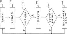
Fig. 3 illustrates the flow chart of example embodiment of confirming the method for PWM dutycycle based on the parameter of measuring;
Fig. 4 illustrates the flow chart that reads the example embodiment of the method for confirming the PWM dutycycle based on battery pack temperature;
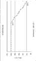
Fig. 5 is the curve map that illustrates the relation between the temperature of PWM dutycycle and battery pack;
Fig. 6 illustrates the flow chart that reads the example embodiment of the method for confirming the PWM dutycycle based on the FET temperature;
Fig. 7 is the curve map that illustrates the relation between the temperature of PWM dutycycle and FET switch;
Fig. 8 illustrates the flow chart of example embodiment that reads to confirm the method for PWM dutycycle based on the battery voltage temperature;
Fig. 9 is the curve map that illustrates the relation between the capacity of PWM dutycycle and battery pack;
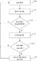
Figure 10 is the flow chart that illustrates the exemplary method of monitor battery pack when instrument start-up;
Figure 11 is the curve map that illustrates temperature and the example relationship between the blanking time;
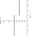
Figure 12 draws the curve map of lithium ion battery with the typical discharge curve of different electric current load discharge; And
Figure 13 is the flow chart that illustrates the example embodiment of the voltage cut-out scheme that is used for power tool application.
Accompanying drawing described here only is used for illustration purpose and the not all possible implementation of selected embodiment, and is not intended to limit the scope of the present disclosure.According to the description that provides at this, but further application will become obvious.Description in this summary of the invention only be used for the illustration purpose with object lesson intention, and be not intended to limit the scope of the present disclosure.Corresponding reference marker is represented corresponding part in the whole text at some views of accompanying drawing.
The specific embodiment
Fig. 1 draws the example arrangement of the electric tool parts of being made up of electric tool 12 and battery pack 14.The electric tool parts can be made up of the instrument facility (not shown) that drives through motor 22.Motor 22 is by 20 controls of discharge control module.Discharge control module 20 is kept watch on the various conditions of electric tool and battery pack, and thereby controls the electric power of motor is exported.The scene of the notion that this example arrangement provides below only being provided as describing.Should be understood that this configuration can only represent the part of internal circuit, therefore can be included in this for clear and unshowned other functional or assembly such as holding circuit.
In this example embodiment,battery pack 14 is couple to electric tool 12 removedly via battery contact or binding post (not shown).Battery pack 14 comprises threebattery unit battery pack 14 adopts the battery with lithium ion battery chemical.For example should be understood thatbattery pack 14 can be by forming based on the chemical of lithium or such as the battery of another chemical of NI-G (NiCd), nickel metal hydride (NiMH) and plumbic acid such as another of lithium metal or lighium polymer.In addition, the imagination obtainsbattery pack 14 is couple to other means of instrument 12, andbattery pack 14 can be integrated in the electric tool 12.
Via 24 controls of ON/OFF variable velocity trigger switch, this ON/OFF variablevelocity trigger switch 24 is when being used by the user by the operator formotor 22, and closure is couple to the switch of variable velocity trigger switch 24.Variablevelocity trigger switch 24 can use various pressure to press by the operator, and the rotary speed ofmotor 22 total distance of advancing corresponding to variable velocity trigger switch 24.For example, whentrigger switch 24 was pressed fully, in the absence of damp condition (following discussion), the rotary speed ofmotor 22 will be with all one's effort.Along with the total distance measurements of advancing oftrigger switch 24 reduces, the rotary speed ofmotor 22 also will reduce.As will discuss, this can realize the electric power signal ofmotor 22 through pulse width modulation.
In the electric tool of the for example screwdriver of preferred reverse operating or drilling machine, electric tool 12 also comprises 2 double (DPDT)switch 28, thus can be through throwing the polarity thatDPDT switch 28 comes circuit for reversing.As can recognize that the electric tool operator can manually promote at the outside button of electric tool orswitch causing motor 22 reverse operations.When the operator manually promoted button or switch,DPDT switch 28 is thrown andmotor 22 will rotate by rightabout.
In addition, the electric tool parts can comprise the LED (not shown).When electric tool can be lighted LED at work the time.LED can be couple todischarge control module 20, makes when the user usesvariable trigger switch 24, for LED provides electric power.
In this example embodiment,discharge control module 20 is arranged in electric tool 12.Although do not require, this configuration has reduced the cost of battery pack, also allows different instruments to use the battery pack of same type.20 controls of discharge control module are delivered to the electric power ofmotor 22, and it drives electric tool facility (not shown).When the operator usedtrigger switch 24,discharge control module 20 was provided with the dutycycle of control signal according to the position of trigger switch 24.More specifically,discharge control module 20 offers FET25 with the control signal after the pulse width modulation, and this FET25 shut-off circuit makes electric power be delivered tomotor 22 then.For the example purpose, hereinafter this switch is calledtrigger switch 24, it should be understood thatswitch 24 can be the switch of other types.When existing by (cutoff) condition, for example be increased to the temperature cutoff threshold when above when battery temperature, the control module of discharging 20 terminations are to the control signal of FET25, open circuit thus and remove the electric power of motor 22.Although the discharge control module with reference to being present in the instrument provides following description, it should be understood that, can realize this disclosed wideer aspect through the control module that is present in the battery pack.
When the operator did not usetrigger switch 24,discharge control module 20 can make the motor short circuit turn offmotor 22 through for exampleclosing brake switch 23 thus.In certain embodiments,brake switch 23 mechanically is couple to variablevelocity trigger switch 24, in case make that this switch is opened, brake switch is just closed, and this is withmotor 22 short circuits.
For example, the voltage thatdischarge control module 20 can monitor battery pack.As shown in Figure 1, the voltage ofbattery pack 14 can be measured at for example node 35 places by discharge control module 20.Thecontrol module 20 of being discharged this voltage reads, make can the monitoring battery unit voltage.If this voltage drops on below the evanescent voltage threshold value, 10.5V for example, the control module of then discharging 20 starts the electric power decay, and its details is in following description.In case battery pack reaches for example 10V of blanking voltage,discharge control module 20 is cut off the electric power to motor 22 through breaking off FET25.In addition, can keep watch on branch (split) cell voltage at node 34 or 36.Fromnode 34 and 36 extensions are the battery contacts that extend from each node.Battery contact be electric wire ornode 34 and 36 is couple to thecontrol module 20 of discharging other be connected.
For the temperature ofmonitor battery pack 14, serviceability temperature sensor 30.An example of temperature sensor is a thermistor, and it is the effective and reliable parts of cost of the temperature in the monitoring circuit.But the imagination obtains also can using the temperature sensor of other types, for example thermometer orthermocouple.Temperature sensor 30 reduces reading of battery pack temperature and offers discharge control module 20.To describe as following, when the temperature ofbattery pack 14 was less than the decay temperature threshold by temperature threshold,discharge control module 20 started the electric power decay.Usesecond temperature sensor 26 to measure the temperature of electric tool 12.Be similar to first temperature sensor, can use thermistor, thermometer or thermocouple to measure temperature.
Although some embodiment that more than described electric tool 12 and be couple to itsbattery pack 14, the imagination obtains and can realize other configurations at the design aspect of electric tool 12 and battery pack 14.In addition, will understand, the each side of below discussing of the present invention can be applied to various platforms and not be to be only limited to above-described configuration.
A kind of means of sending electric power to motor provide carries out pulse width modulation (PWM) to the electric power signal or the control signal that send to FET25.Pulse width modulation is the electric power means of sending the variable quantity of electric power to motor.The dutycycle indication of control signal is delivered to the mean value of the voltage of motor.Therefore, 80% dutycycle is corresponding to the output of 80% voltage, this through make voltage open the cycle that reaches 80% and close 20% of the cycle of reaching and obtain.This can be through making FET closed 80% time and remaining 20% the time of opening realize.Therefore, through the value of control PWM dutycycle, can realize various voltage outputs.
As stated, variable velocity trigger switch 24 total distance of advancing can influence the rotary speed of motor 22.Be set to control the rotary speed ofmotor 22 based on the value of the expectation rotary speed ofmotor 22 through the PWM dutycycle.For example, if the operator presses ultimate range with this triggering, then the PWM dutycycle will be initially set to 100%.Along with the pressure that is applied to triggering 24 reduces, expression exists and hopes to slow downmotor 22 thus, the PWM dutycycle also reduces.
In addition, if realized damp condition, then can reduce the PWM dutycycle to reach the use that prolongs motor before the cut-off condition.To describe as following;Discharge control module 20 is with each assembly of adviser tool; And if any assembly is near cut-off condition, promptly be in damp condition, the control module of then discharging 20 based on the damp condition state under the corresponding value of assembly calculate the PWM dutycycle.To recognize, the PWM dutycycle ofcontrol motor 22 be set to equal the PWM dutycycle corresponding withtrigger switch 24 perhaps with the damp condition state under the corresponding PWM dutycycle of assembly in the smaller.
In most of the cases, will not realize damp condition.In these instances, the PWM dutycycle can be set to 100% or corresponding any other value of distance of advancing with trigger switch 24.In other cases, will realize cut-off condition.In these instances, the PWM dutycycle should be set to 0%.Also do not reach under the situation of cut-off condition in damp condition, the PWM dutycycle can be set at maximum PWM dutycycle, for example 100% and minimum PWM dutycycle, for example between 20% or 0%.In addition, the imagination obtains, along with the parameter value of being kept watch near cut-off condition, dutycycle can slowly reduce, and causes the electric power decay of electric power output thus.As stated, if the userunclamps trigger switch 24, then the position oftrigger switch 24 possibly cause the PWM dutycycle littler than the dutycycle corresponding with damp condition.
Fig. 2 A draws the example input and output to discharge control module 20.Discharge control module 20 receives the signal of the various measurement parameters of expression from each sensor or node.In this example,discharge control module 20 receives battery pack temperature signal 50, receives heap (stack)voltage signal 52, receivesFET drain voltage 56 from tool component temperature sensor receiving toolpart temperatures signal 54 and from FET from the node relevant with battery pack from battery pack temperature sensor 30.The parameter of these measurements is exemplary and is not intended to limit by any way.To recognize, can be by the parameter ofdischarge control module 20 other measurements of supervision, such as motor speed, motor torsional moment, instrument rotation etc.
When instrument was opened,discharge control module 20 can be carried out control circulation, keeping watch on the parameter of each measurement, and will confirm the PWM dutycycle ofelectric power signal 56 based on the parameter of measuring.Below any damp condition threshold value of any one condition of whether keeping watch on being directed against in the parameter thatdischarge control module 20 is measured, for example whether battery pack temperature is too high.If then can calculate decay PWM dutycycle based on the sensor values of keeping watch on.If the parameter of two or more measurements needs the electric power decay, the decay PWM dutycycle of being calculated that then can be minimum is set to actual PWM dutycycle.
Fig. 2 B illustrates the main control circulation that when the user opens electric tool, begins to carry out in step 60.This control circulation will continue to carry out, and be closed or will be operated under the low-power consumption mode up todischarge control module 20 up to electric tool, be described below.Under one situation of back, can use the WatchDogTimer control module 20 of will discharging to turn back to the total power dissipation pattern.At step 62-68, through control loop start the whole bag of tricks or use with the parameter of keeping watch on each measurement and based on the PWM dutycycle of the parameter control discharge control module of measuring 20.The above example that is used for the main control circulation is provided, and only is provided for example by the quantity of the method for controlling recursive call.In addition, sequentially carry out although Fig. 2 B draws method, the imagination obtains that this method can also walk abreast or carries out simultaneously.
Fig. 3 draws can be by the exemplary method ofdischarge control module 20 execution.Discharge control module 20 receives the signal of value of the parameter of each measurements of expression, and confirms that concrete parameter value is whether below the respective attenuation threshold value.If this concrete parameter value is below the respective attenuation threshold value, promptly electric tool is in damp condition, then based on the calculation of parameter PWM dutycycle of measuring.The PWM dutycycle of being calculated is compared with actual PWM dutycycle to confirm whether actual PWM dutycycle need be set to equal this PWM dutycycle.
Instep 100, control circulates call subroutine to determine whether the carrying out electricpower decay.In step 110, any one of each sensor or the node ofdischarge control module 20 from electric tool or battery pack receives the signal of the parameter of each measurement of expression.For example,discharge control module 20 can be from temperature sensor reception signal of one of the temperature ofmonitor battery pack 14, temperature of FET25 and the voltage that reads from the node between two battery units.The imagination obtains, and also can keep watch on other conditions of electric tool or battery pack.
Instep 112, with parameter of measuring and decay threshold.For example, the temperature that reads from battery pack can be compared with the battery pack temperature threshold of decaying.In this example,, then reach damp condition, and method advances tostep 114 if temperature reads above battery pack decay temperature threshold.If do not reach damp condition, then method is got back to the control circulation.
Next, if reach damp condition, then calculate decay PWM dutycycle in step 114.The type that depends on damp condition, calculating can change.Below provide and the relevant example of PWM dutycycle that calculates to concrete damp condition.A general example is the function that the linear equation of expression PWM dutycycle is calculated as the condition of being kept watch on.Known maximum PWM dutycycle for example 100%, minimum PWM dutycycle for example 20% or 0%, damp condition is corresponding with the parameter of minimum and maximum PWM dutycycle and measurement, decay PWM dutycycle may be calculated as follows:
Wherein FCStart is the beginning of damp condition, promptly when how being worth of the parameter of measuring, starts the electric power decay, and FCEnd is the end of damp condition, and MC is the parameter value of measuring.The imagination obtains, and can incorporate the various models that are used to calculate decay PWM dutycycle into.Although the disclosure has been discussed the PWM dutycycle of calculating the decay of substantially linear ground, also can realize ladder (step) model, multinomial model or exponential decay model.In case calculated the PWM dutycycle, this method just advances tostep 116.
Instep 116, actual PWM dutycycle, be that the current PWM dutycycle that just is being operated in of electric tool is compared with the decay PWM dutycycle of being calculated.If actual PWM dutycycle is greater than the decay PWM dutycycle of calculating, then instep 118, the PWM dutycycle that actual PWM dutycycle is set to calculate.If actual PWM dutycycle is not more than the decay PWM dutycycle of calculating, then subprogram turns back to the control circulation.
The decision that actual PWM dutycycle is not updated to the decay PWM dutycycle of calculating when decay PWM dutycycle during less than the PWM dutycycle confirmed by trigger position is based on following hypothesis: below the decay PWM dutycycle that the PWM dutycycle possibly be set to calculating, because the parameter of another measurement maybe be than the parameter of the sensor measurement of in above-mentioned steps, analyzing more near cut-off condition.For example, if battery unit almost completely exhausts and actual PWM dutycycle is set to reflect this condition, the battery pack temperature that has then just surpassed the damp condition threshold value should not increase dutycycle.But, in certain embodiments, the decay PWM dutycycle that actual PWM dutycycle can be set to calculate and no matter two values more how.
In certain embodiments, can realize that this method makes that when reaching cut-off condition, the PWM dutycycle is calculated as 0% when calculating the PWM dutycycle.But in other embodiments, the parameter of measurement is compared to determine whether to realize cut-off condition with predetermined cut-off condition.If realized cut-off condition, then this method can the PWM dutycycle be set to 0%, and this method finishes.
As cognoscible, when electric tool in use, this method can be carried out continuously.Perhaps, this method can be carried out on schedule at interval.And the imagination obtains, and can carry out other variations of this method.For example, instep 112, if there is not damp condition, then actual PWM dutycycle can be set to 100%.If before realized damp condition, start electric power decay thus,, but before recomputating the PWM dutycycle, remove damp condition then this variation can be useful.
Each condition and protection instrument or battery pack that the method for below briefly describing can be used to keep watch on electric tool are not damaged.In the instrument formerly, practice is when 100% electric power is exported, to allow each condition variation at tool work, takes place up to cut-off condition, and at this moment instrument is closed and can not operates up to revising cut-off condition.But, use the operating time of the electric tool that above-mentioned general framework can obtain increasing and the instrument and/or the battery pack life-span of prolongation.
In certain embodiments, can the monitor battery pack temperature whether be in damp condition with definite battery pack.If battery pack temperature has has met or exceeded the damp condition threshold value, then calculate the PWM dutycycle corresponding with battery pack temperature.
Fig. 4 illustrates can be by the flow chart of the method fordischarge control module 20 execution monitoring batterypack temperatures.In step 200, control recursive call subprogram is with the monitor batterypack temperature.In step 210, the temperature of monitor battery pack.As previously mentioned, in certain embodiments, temperature sensor can be a thermistor.In these embodiment,discharge control module 20 is measured the voltage of battery pack thermistor input place.In battery pack thermistor input place measured voltage is the part of battery voltage.According to the test data of previous collection, the resistance of thermistor when actual temp is known.Therefore, through the voltage of supervision thermistor input place and the voltage at battery pack place, can calculate the ratio of battery voltage and thermistor input voltage.To recognize that this ratio is corresponding to the resistance of thermistor when the actual temp.Therefore, the ratio that is calculated can be used to inquire about look-up table, returns the temperature corresponding with this ratio thus, will recognize, this look-up table can be stored in the nonvolatile memory relevant with thecontrol module 20 of discharging.
Instep 212; The current voltage of cells known group; This method reads and voltage corresponding to battery pack decay temperature threshold at the voltage of thermistor input place through thecontrol module 20 of relatively discharging, and determined battery pack temperature and the battery pack temperature threshold of decaying is compared.Should be understood that in certain embodiments, the ratio that is calculated, be battery voltage with the ratio of thermistor input voltage can with compare corresponding to the estimated rate of battery pack decay temperature.If this battery pack temperature is more than threshold value, then this method advances to step 214.If not, then this method is got back tostep 210.
In step 214, calculate decay PWM dutycycle.As said, can useequality 1 to calculate the PWM dutycycle.Particularly, can use with the calculating decay PWM dutycycle of getting off:
V whereinTI_StartBe that the voltage corresponding with the beginning of damp condition reads VTI_ENDBe that the voltage corresponding with the end of damp condition reads, and VTI_MeasuredBe actual measurement voltage in thermistor input place.In addition, should be realized that, if this method is just being carried out this step, then VTI_Start≤VTI_Measured≤VTI_ENDAnd as previously mentioned, MaxPWM is maximum PWM dutycycle, for example 100%, and MinPWM is minimum PWM dutycycle, for example 20%.As said, not only depend on temperature but also depend on the residual voltage of battery unit at the voltage of thermistor input place.Therefore, VTI_StartAnd VTI_ENDValue will change based on battery cell voltage.Can obtain this value from the data of previous collection, these previous data of collecting can be stored in the memory relevant with thecontrol module 20 of discharging.To recognize that look-up table can be stored in different cell voltages is linked to corresponding VTI_StartAnd VTI_ENDMemory in.Also will recognize, and can use the actual measurement temperature of battery pack to replace the measured voltage value.To recognize, and can use the measurement temperature of battery pack to replace measured voltage values.In the case, will replace VTI_StartAnd VTI_ENDBegin temperature value and end temp value and use.
In example embodiment, when battery pack temperature can begin damp condition during at 60 ℃, and can finish during at 65 ℃ when this temperature.In this example, maximum PWM dutycycle be 100% and minimum PWM dutycycle be 20%.Therefore, using equality (2), is 62 ℃ if the Current Temperatures of battery pack is similar to, and the PWM dutycycle that then decays should be approximate 68%.Fig. 5 has drawn the curve map that the example relationship between battery pack temperature and the decay PWM dutycycle is shown.
In case calculated decay PWM dutycycle, then instep 216, with decay PWM dutycycle with actual PWM dutycycle, be that the current dutycycle that just is being operated in of instrument is compared.If decay PWM dutycycle is less than actual PWM dutycycle, then instep 218, the actual PWM dutycycle PWM dutycycle that is set to decay.Do like this is because the temperature of battery pack is just increasing and the approaching temperature of ending.If decay PWM dutycycle is greater than actual PWM dutycycle, then this method is got back to step 210, and actual PWM dutycycle does not change.This takes place in the time of can beginning to descend owing to decay in the temperature of battery pack.But the imagination obtains, and in certain embodiments, can realize reverse attenuation, and actual thus PWM dutycycle is always substituted by the decay of being calculated PWM dutycycle, makes that the PWM dutycycle increases along with temperature reduces.
The imagination obtains, and this method can be moved or move with predetermined time interval continuously.In addition, in certain embodiments,discharge control module 20 can check that the voltage in thermistor input place reads whether below cut-off condition.In these embodiment,, then can cut off electric power and be reduced to below the cutoff threshold up to battery pack temperature if this voltage reading is taken at below the cutoff threshold.In addition, will recognize that the threshold value that in above example, is provided only is provided for example and is not intended to is restrictive.Thereby the order of each step is not compulsory, and will recognize and can carry out each step by different orders.In addition, the imagination obtains, and can take the step of replacing and is not that each step all is necessary.
In another aspect of the present disclosure, can the monitoring switch part temperatures.To recognize that when period that electric tool is used to prolong, the temperature of other assemblies in FET25 or the electric tool circuit possibly be increased to the point that possibly damage those assemblies.Therefore, can keep watch on the temperature of electric tool, in case and this temperature reach the value that needs electric power decay, the PWM dutycycle of electric power signal is decayed.
Fig. 6 illustrates the flow chart that can be carried out the method for monitoring switch part temperatures by discharge control module 20.In certain embodiments,discharge control assembly 20 temperature of keeping watch on FET25 shown in Figure 1.Temperature sensor can be thethermistor 26 that is adjacent to arrange with FET, the voltage that the control module of discharging thus 20 is measured in second thermistor input place.Because relative with the battery pack temperature sensor, thermistor is connected to constant pressure source.Therefore, can be (the hard coded) of hard coded with the corresponding voltage of switch temperature decay threshold value, because do not change with the variation of battery voltage with the beginning of electric power decay and the end corresponding voltage value general of electric power decay.Except this was explained, the step of Fig. 6 corresponded essentially to the step of Fig. 4.
Instep 300, control recursive call temperaturemonitoring subprogram.In step 310, measure voltage in 26 inputs place ofsecond thermistor.In step 312, measured voltage is compared with the voltage of the threshold value that decays corresponding to switch temperature.If this voltage less than with the corresponding voltage of switch temperature decay threshold value, then based on switch temperature calculating PWM dutycycle, and this method comes 314.If this voltage greater than with the corresponding voltage of switch temperature decay threshold value, then switch temperature is also less than through the overdamping threshold value, and method is got back tostep 300.
Instep 314, calculate decay PWM dutycycle.Calculate the PWM dutycycle based on yield value and deviant.This yield value can be calculated as as follows:
This deviant can be calculated as as follows:
Offset=Gain×VTFET_Start-MaxPWM (4)
Use and should gain and skew, decay PWM dutycycle may be calculated as follows:
FadePWM=Gain×VTFET_Measured-Offset (5)
Notice that this gain and deviant can be based on fixed value, feasible in certain embodiments, this gain and deviant can be hard coded within the memory relevant with thecontrol module 20 of discharging.In these embodiment, can calculate decay PWM dutycycle based on the voltage measurement that receives.In other embodiments, can use following formula to calculate decay PWM:
V whereinTFET_StartBe the beginning corresponding voltage value with damp condition, VTFET_ENDBe the end corresponding voltage value with damp condition, and VTFET_MeasuredBe actual measurement voltage in second thermistor input place.And as previously mentioned, MaxPWM is maximum PWM dutycycle, for example 100%, and MinPWM is minimum PWM dutycycle, for example 20%.As said, not only depend on temperature but also depend on the residual voltage of battery unit at the voltage of second thermistor input place.Therefore, VTI_StartAnd VTI_ENDValue can be based on the threshold temperature place expection voltage and by hard coded.To recognize, and can use the treatment temperature of FET to replace the measured voltage value.In the case, will use beginning temperature value and end temp value to substitute VTI_StartAnd VTI_END
In the exemplary embodiment, when switching temperature during at 95 ℃ attenuation state begin and finish during at 100 ℃ when temperature.In this embodiment, maximum PWM dutycycle be 100% and minimum PWM dutycycle be 20%.Thereby, adopt equality (3)-(5) or (6), if the Current Temperatures of battery pack is approximately 99 ℃, the PWM dutycycle that decays so should be about 36%.Fig. 7 has described the curve map that concerns between switching temperature and the decay PWM dutycycle.
In case calculated decay PWM dutycycle, can it be compared with actual PWM dutycycle, actual PWM dutycycle, that is, and the dutycycle at the current operation of instrument place.If decay PWM dutycycle is less than actual PWM dutycycle, the actual duty cycle PWM dutycycle that is set to decay so.Do like this is because the temperature of switching rises and be approaching by temperature.If decay PWM dutycycle is greater than actual PWM dutycycle, method is back to 300 and keep actual PWM dutycycle constant so.
In certain embodiments,discharge control module 20 determines whether that voltage readings is lower than cut-off state.In these embodiment,, cut off electric power so and be reduced to below the cutoff threshold until switching temperature if voltage readings is lower than cutoff threshold.Imagine this method continuously-running or with as by thedischarge control module 20 the determined preset time of control loop move at interval.Further, recognize that the threshold value that provides in above the giving an example only is used for giving an example and not being intended to for restrictive.In addition, the order of step be not compulsory and recognize can be different the order execution in step.In addition, imagination can be carried out replacement step and not be that each step all is necessary.
Adopt thermistor astemperature sensor 30 in certain embodiments, thermistor is positioned at just (+) end of trigger switch.In the prior art, the battery pack thermistor is positioned at negative (-) end of trigger switch 24.Yet, configuration as shown in Figure 1, (-) end that thermistor is positioned overtrigger switch 24 causes electric current to leak.Like what observe among Fig. 1, triggerswitch 24 is in (-) end of electric power tool circuit.As a result of, if thermistor is positioned over (-) end oftrigger switch 24, electric current will be from battery pack, flow through thedischarge control module 20 and the thermistor of flowing through, thus walk around variable velocity trigger switch 24.Because need being used,trigger switch 24 make electric current flow, so, can avoid electric current to leak through thermistor being positioned over (+) end oftrigger switch 24.
For further anti-heads, adopt block diode in certain embodiments.As shown in Figure 1 with block diode 37 be positioned overthermistor 30 and the discharge control module between.Also block diode 38 and 39 is positioned overnode 36 and 34 and the battery branch of discharge between thecontrol module 20 respectively.Diode is the device that helps the control electric current to flow in the circuit, and its help remains on the isolation of power supply in the circuit.Block diode with current configuration, assists in ensuring that electric current does not flow back into battery fromdischarge control module 20.
In the disclosure on the other hand, but the voltage ofdischarge control module 20 monitoring battery groups.Because battery pack discharged, when group voltage reaches predetermined voltage readings, but the decay ofdecay control module 20 initialization electric power.
Fig. 8 illustrates bydischarge control module 20 and carries out so that the flow chart of monitoring battery groupvoltage method.In step 400, control loop calls the voltage monitoring subprogram.As shown in Figure 1, read battery voltage from node 35, node 35 reference sometimes is branch (tap).Thereby, read voltage so that monitoring battery group voltage from node 35 in step 410.Further recognize the voltage that also can confirm single battery or battery combination.For example, can read at the separation stack voltage of node 34 so that confirm the voltage of battery unit 32C.Employing also can be confirmed the voltage ofbattery unit
Like voltage readings and the voltage attenuation threshold ofstep 412 with battery unit.If voltage readings is lower than the voltage attenuation threshold value, method proceeds to step 414 so, and the PWM dutycycle is calculated based on battery cell voltage in the there.If voltage readings is higher than the voltage attenuation threshold value, battery still has enough capacity so, and does not need the electric power decay.For example, the voltage attenuation threshold value can be corresponding with the battery capacity of the highest electric charge remaining 5%.
Calculate decay PWM dutycycle in step 414.Can calculate decay PWM dutycycle based on yield value and deviant.Yield value can be by following calculating:
Deviant can be by following calculating:
Offset=Gain×VBC_Start-MaxPWM (8)
Adopt gain and skew, can be by following calculating decay PWM dutycycle:
FadePWM=Gain×VBC_Measured-Offset (9)
Notice that gain and deviant can be based on fixed values, thus in certain embodiments, can with memory that dischargecontrol module 20 is associated in hard coded gain and deviant.In these embodiment, decay PWM dutycycle can be calculated decay PWM dutycycle based on the voltage measurement that receives.In other embodiments, can adopt following equation to calculate decay PWM dutycycle:
In the equality in front, VBC_StartBe the magnitude of voltage of the battery pack corresponding, V with the beginning of attenuation stateBC_ENDBe the magnitude of voltage of the battery pack corresponding with the end of attenuation state, and VBC_MeasuredBe voltage in node 34 actual measurements.Also have, as aforementioned, MaxPWM is maximum PWM dutycycle, for example, 100%, and MinPWM is minimum PWM dutycycle, for example, 20%.
In an exemplary embodiment, when battery unit (battery cell) when reaching 10.5V attenuation state begin and finish during for 10V when battery unit.In this example, maximum PWM dutycycle be 100% and minimum PWM dutycycle be 20%.Thereby, adopt equality (7)-(9) or (10), if the current voltage of battery pack is approximately 10.2V, the PWM dutycycle that decays so should be greater than being 52%.In case calculated decay PWM dutycycle, dutycycle is compared with actual PWM dutycycle, actual PWM dutycycle promptly, the dutycycle at the current operation of instrument place.If decay PWM dutycycle is less than actual PWM dutycycle, the so actual PWM dutycycle PWM dutycycle that is set to decay.Method is back to 410 then.
Fig. 9 has described the curve map that concerns between demonstration battery capacity and the decay PWM dutycycle, and it is directly related with battery capacity wherein to organize voltage.Imagine this method continuously-running perhaps to move at interval like the determined preset time of control loop by the discharge control module.In addition, recognize that the threshold value that provides in above the giving an example only is used for giving an example and not being intended to for restrictive.In addition, the order of step be not compulsory and recognize can be different the order execution in step.In addition, imagination can be carried out replacement step and not be that each step all is necessary.Additionally, also can method be applied to monitor the voltage of independent battery unit.
Though we have discussed evanescent voltage as being used for indication through group temperature, group voltage, module temperature, instrument rotation, motor torsional moment etc.; Predetermined cut-off state near method; Also imagined other method of the marking tools user that can implement of for example LED indication (that is, based on the approximate frequency scintillation LED to change of monitoring) by limitation.Additionally or replacedly, can carry out motor ' pulse ' through changing PWM at specific clock switch.These just are used for indicating to the user some other methods of the situation of appearance.
In disclosure others, configurationdischarge control module 20 reads so that prevent the mistake that under cold state, starts.As mention, when battery pack arrived under-voltage (under voltage) state,discharge control module 20 can confirm to have arrived cut-off state.In this case, with the electric power that cuts off formotor 22, thereby prevent that battery pack from getting into the deep discharge state.Yet a kind of problem that is associated with rechargeable battery pack is in low temperature, for example, below 10 ℃, to can observe the pressure drop of loaded increase.Under these cold states, when the tool operator opening power first time, the high swash of wave will cause relatively large pressure drop.Additionally, cold state can cause the impedance in the battery circuit to increase, and further worsens pressure drop.
In order to resist this problem, configurationdischarge control module 20 reads with the voltage of ignoring predetermined amount of time (for example 300ms), and after this reference is the blanking time section.The blanking time section fordischarge control module 20 allow motors in control measurement parameter not to determine whether to reach a period of time of moving under the situation of the condition of closing.During the blanking time section,discharge control module 20 is withbias voltage FET 25, thus permissioncurrent direction motor 22, and the uncertain under-voltage state that whether exists.In case crossed the blanking time section,discharge control module 20 will be recovered the monitoring of various input signals, so that determine whether to exist under-voltage state, and if should exist this state can cut off motor really.
Yet a shortcoming with predetermined blanking time section is that according to temperature, the blanking time section maybe be too short or long.If the blanking time section is too short, go bail for by the voltage reading of cold state hold adverse effect in the blanking time section can pass.Therefore, though prematurely the closing tool battery pack in fact have enough voltage and come supply motor 22.On the other hand, if the blanking time section is long and infact battery pack 14 exhausts, even if the residual charge so in the battery pack should force instrument to be closed,battery pack 14 possibly allow discharge.
As the parts of repairing above situation about describing, some embodiment implementation basis are the variable blanking time section of the factor that reads of Influence of Temperature voltage for example.For example, if battery pack temperature is relatively low, so the blanking time section compare when battery pack temperature is higher relatively, should schedule to last longer.Therefore, the time period of blanking time section can be according to the temperature of battery pack.
Figure 10 illustrates the exemplary method that is used for monitoring battery group afterstartup.At step 1000 operator turns onpower instrument.In step 1002, read battery pack temperature fromtemperature sensor 30.
In case confirmed battery pack temperature,discharge control module 20 is confirmed the blanking time section instep 1004 based on temperature.Can confirm the blanking time section with many modes.For example, with the memory that is associated ofdischarge control module 20 in question blank can be arranged.In question blank, each temperature can have corresponding blanking time section or the temperature threshold that is used to be provided with the blanking time section.For example, Figure 11 shows the curve map as the blanking time section of the function of temperature.As scheme visible, in case temperature less than 5 ℃, the blanking time section is from 300ms value added 500ms.In alternative embodiment, can adopt equality to confirm the blanking time section.Imagination can adopt linear equality, second order or more the equality of high-order equality, logarithm equality, derivative equality or other type the blanking time section is set.
In case confirmed the blanking time section, electric power tool comprises incontrol module 20 monitoring of not discharging under the situation of measurement parameter of battery pack state to be operated, until having crossed the blanking time section.In case accomplished the blanking time section,discharge control module 20 begins to monitor the measurement parameter that comprises battery voltage in step 1008.Can recognize that the accurate function of confirming the blanking time section also can be according to the manufacturer of battery unit chemistry and battery unit.
Figure 12 illustrates the typical discharge curve of lithium ion battery with the discharge of different electric current load.The discharge of battery should be close to before the precipitous decline of voltage appearing at.Though can adopt absolute voltage to end (for example, 2.5 volts), when high capacity more by occurring too early.For example, be labeled as 2600 curve and represent the current discharge of 20 peaces.Under this situation, the very short time current before the absolute voltage that arrives 2.5V ends will discharge.Become known for compensating strategy for current draw voltage cut-off value.These strategies comprise to be measured electric current and changes the voltage cut-off threshold value based on the electric current of measuring.Be used to measure the other current measurement and the restricting circuits of Technology Need of electric current.Thereby expectation is implemented the voltage cut-off plan and is not needed directly to measure electric current.
The technology that is used to measure electric current be with battery himself as using along separate routes.In this technology, (for example, each second is once) interruptive current periodically.In discharge current from battery and interruptive current extraction, measure cell voltage.In the exemplary embodiment, the impedance of cells known unit is in every battery 48 milliohm levels.Under this situation, can be by following calculating electric current:
Electric current=(cell voltage of cell voltage-electric current unlatching that electric current is closed)/48 milliohms
Because battery impedance is conversion in time, can battery impedance be stored in the memory and be updated periodically.For example, can in battery charge, confirm battery impedance.Because charger is exported current known to battery, electric current unlatching capable of using and electric current are closed and are measured cell voltage.Can use this change in voltage to confirm then and adjust the battery impedance value of being stored.Disclosure expection is used for confirming and/or upgrading other technology of battery impedance.
Further described replacement voltage cut-off scheme with reference to Figure 13.During battery discharge, periodically interrupt a bit of time of electric current of extracting from battery.This short time should not felt perhaps for the user otherwise detected interruption (for example, 3-5 millisecond).At intercourse, battery is carried out voltage measurement.Can be to single battery, the part of battery pack or overall stack (stack) are carried out voltage measurement.Then voltage measuring value is compared with target cutoff voltage.Surpass target cutoff voltage if voltage measuring value rises more than target cutoff voltage or at intercourse, do not think that battery is abundant discharge.In this case, stop break period and recover from the current draw of battery.On the other hand, end, stop the discharge of battery so if voltage measuring value is lower than target.By this way, directly measure the dormancy voltage of battery and can avoid current compensation.
In this example embodiment, periodically or when the measured value of load voltage when battery extracts electric current (that is, when from) drops to load voltage threshold value (for example, for 2.7 volts of lithium ion batteries) carry out voltage measurement when following.When battery begins discharge, begin interrupt timers so that reach periodic samples (for example, each second once) 2610.The disclosure is also expected other technology that is used to reach the periodic sampling rate.
Next, in battery discharge, carry out 2612 battery voltage measurements.Voltage measurement can be to a part or the overall stack of single battery, battery pack.In any case, with voltage measuring value and load voltage threshold 2614.If it is expired at 2616 detection interrupt timers that voltage measuring value surpasses the load voltage threshold value.Also do not have expiredly as long as voltage measuring value surpasses load voltage threshold value and timer, repeat this circulation.
In case timer is expired, interrupt carrying outsecond voltage measurement 2634 from the electric current of battery extraction and at intercourse 2632.In an exemplary embodiment, has inherent delay from central outage stream until the moment of carrying out second voltage measurement by microcontroller; This time-delay (preferably with the 2ms level) allows voltage to return its dormancy value.In another kind of embodiment, has the necessary time-delay of before carrying out second voltage measurement, carrying out for control module.In any case, successively second voltage measuring value is compared with target cutoff voltage 2636.Though it can be for identical with the load voltage threshold value, target cutoff voltage is preferably floating voltage threshold value (for example, for 2.7 volts of lithium ion batteries).If second voltage measuring value is not less than target cutoff voltage, so current EOI and can recover battery discharge.Under this situation, at 2630 replacement interrupt timers.End if second voltage measuring value is lower than target, stop battery discharge so as in 2640 indications.
Likewise, if voltage measuring value surpasses the load voltage threshold value, interrupt carrying outsecond voltage measurement 2620 2618 so from the current draw of battery and at intercourse.Once more second voltage measuring value is compared with target cutoff voltage 2622.End if second voltage measuring value is lower than target, indicate the discharge that stops batteries so as 2640.
On the other hand,, ends second voltage measuring value so current EOI and the discharge that can recover battery if being not less than target.For being lower than its threshold value at load voltage when, avoid too much voltage measurement, at 2626 initialization, second timer (at this also with reference to being empty timer).Second timer is expired will not measure cell voltage once more until this.In case second timer is expired, control is back to step 2612 and reprocessing.
As in this use; Term module can refer to, for a part or comprise application-specific IC (ASIC), electronic circuit, processor (shared, special-purpose or divide into groups) and/or memory (shared, special-purpose or divide into groups), one or more softwares of the function that its execution provides a description or firmware program, combinational logic circuit and/or other are fit to set up.
The embodiment that provides preamble to describe is used for diagram or describes purposes.It is not intended to for exhaustively or the restriction the present invention.The individual component of specific embodiment or characteristic usually are not limited to this specific embodiment, on the contrary, even if do not illustrate especially or describe, at appropriate location, can change each other and can in embodiment chosen, use.Identical mode also changes with many modes.These variants are not regarded as deviating from the present invention, and all such modification is intended to by included in the scope of the present invention.
Claims (24)
1. electric tool with battery-powered motor is characterized in that comprising:
Be used for electric power being transported to from battery the parts of motor according to operator's input;
Be used to detect the parts of the condition of electric tool, wherein said condition indication electric power close coming; And
Be used in response to the condition that is detected, through use be present in said electric tool controller, make the parts that are transported to the electric power decay of motor from battery.
2. electric tool as claimed in claim 1, the parts that it is characterized in that being used to detecting the condition of electric tool comprise that also the controller that uses electric tool keeps watch on the parts of the parameter of this instrument.
3. electric tool as claimed in claim 2 is characterized in that also comprising: be used to make the decay parts of a value of the electric power of conveying, said value is as the calculated value of the function of parameter value.
4. electric tool as claimed in claim 2 is characterized in that being used to making the parts of the electric power decay of conveying to reduce the electric power of carrying according to the function of parameter value, wherein this function be linearity, ladder, index or polynomial at least one.
5. electric tool as claimed in claim 2 is characterized in that also comprising being used for the parts that transmit electric power to motor according to the position of the trigger switch on the said instrument.
6. electric tool as claimed in claim 2 is characterized in that also comprising the parts that are used for monitoring battery voltage, starts the decay of the electric power of carrying and drop on the parts below the voltage cut-off threshold value according to the linear electric power of carrying that reduces of the function of cell voltage up to cell voltage when following when cell voltage drops on the voltage attenuation threshold value.
7. electric tool as claimed in claim 2 is characterized in that also comprising the temperature that is used for keeping watch on electric tool, when this temperature surpasses temperature damping's threshold value, starts the decay of the electric power of carrying and reduces the electric power of carrying surpasses the temperature cutoff threshold up to this temperature parts according to the function of temperature is linear.
8. electric tool as claimed in claim 2 is characterized in that also comprising: the parts that are used for keeping watch on the temperature of the battery pack of holding battery; The electric power that is used for the parts of the decay of the electric power of startup conveying when this temperature surpasses temperature damping's threshold value and is used for carrying according to the linear reduction of the function of temperature is up to the parts of this temperature above the temperature cutoff threshold.
9. electric tool as claimed in claim 1 is characterized in that also comprising the parts that are used for recently making through the duty that the adjustment slave controller sends to the control signal after the pulse width modulation of control end of the switch of in series arranging with battery the electric power decay of conveying.
10. electric tool system is characterized in that comprising:
Tool component with motor;
Battery pack, it optionally is couple to said tool component and works to motor electric power to be provided; And
The discharge control module, it is keeping watch on the parameter of marking tools operation when motor transmits electric power from battery pack, and the amount of the function that the electric power that is transported to motor from battery is decayed be calculated as parameter value.
11. like the electric tool system of claim 10, it is characterized in that said discharge control module through reduce the electric power decay that the electric power of carrying makes conveying according to the function of parameter value, wherein this function be linearity, ladder, index or polynomial at least one.
12. electric tool system like claim 10; The voltage that it is characterized in that said discharge control module monitoring battery; When cell voltage drops on the decay that the voltage attenuation threshold value starts the electric power of carrying when following, and drop on below the voltage cut-off threshold value up to cell voltage according to the linear electric power of carrying that reduces of the function of cell voltage.
13. electric tool system like claim 10; It is characterized in that also comprising the temperature sensor that is arranged in the said tool component; Wherein said discharge control module is configured to receive temperature survey from this temperature sensor; When this temperature surpasses temperature damping's threshold value, start the decay of the electric power of carrying, and surpass the temperature cutoff threshold up to this temperature according to the linear electric power of carrying that reduces of the function of temperature.
14. electric tool system like claim 10; It is characterized in that also comprising and be arranged in the said battery pack and the temperature sensor of communicating by letter with said discharge control module; Wherein said discharge control module is kept watch on the temperature in the said battery pack, when this temperature surpasses temperature damping's threshold value, start the electric power of carrying decay parts and be used for surpassing the temperature cutoff threshold up to this temperature according to the linear electric power of carrying that reduces of the function of temperature.
15. like the electric tool system of claim 10, it is characterized in that said discharge control module through adjustment send to battery pack in the pulse width modulation of control end of the switch in series arranged of battery unit after the duty of control signal recently control the electric power that is transported to motor.
16., it is characterized in that said discharge control module is present at least one of said tool component or battery pack like the electric tool system of claim 15.
17. like the electric tool system of claim 15, it is characterized in that also comprising being arranged on the said tool component and the trigger switch of communicating by letter the feasible dutycycle that said control signal is set according to the position of said trigger switch with said discharge control module.
18. electric tool system like claim 17; During the dutycycle that it is characterized in that being provided with less than position according to said trigger switch when the calculated value of dutycycle; The value that the said dutycycle of said discharge control module is set to calculate according to the function of parameter value; And when dutycycle that the calculated value of dutycycle is provided with greater than the position according to said trigger switch, the dutycycle that keeps the position according to said trigger switch to be provided with.
19. one kind by the battery powered electric tool with a plurality of battery units, it is characterized in that comprising:
Be used for when battery flows out, measuring the parts of the voltage of battery at electric current;
Be used for temporary transient interruptive current to measure the parts of the voltage of battery under idle condition;
Be used to measure the parts of the voltage of battery under idle condition;
Be used for the voltage measurement of zero load and the parts of voltage cut-off threshold; And
Be used for when unloaded voltage measurement surpasses the voltage cut-off threshold value, recovering parts from the electric current of battery outflow.
20., it is characterized in that also comprising the parts that are used for stopping during less than the voltage cut-off threshold value current discharge of battery when unloaded voltage measurement like the electric tool of claim 19.
21. like the electric tool of claim 19, it is characterized in that also comprising be used for current interruptions with time period of millisecond magnitude to measure the voltage of battery under idle condition.
22., it is characterized in that also comprising being used to postpone parts to the voltage measurement of battery under idle condition like the electric tool of claim 19.
23. like the electric tool of claim 19, the parts that it is characterized in that being used for measuring voltage also comprise the parts of the voltage of a part that is used to measure single battery unit or each battery unit.
24., it is characterized in that also comprising being used for interruptive current periodically just when battery flows out, to measure the parts of the voltage of battery under idle condition at electric current like the electric tool of claim 19.
Applications Claiming Priority (2)
| Application Number | Priority Date | Filing Date | Title |
|---|---|---|---|
| US32169910P | 2010-04-07 | 2010-04-07 | |
| US61/321,699 | 2010-04-07 |
Publications (1)
| Publication Number | Publication Date |
|---|---|
| CN202225179Utrue CN202225179U (en) | 2012-05-23 |
Family
ID=44315366
Family Applications (5)
| Application Number | Title | Priority Date | Filing Date |
|---|---|---|---|
| CN2011202191819UExpired - Fee RelatedCN202151853U (en) | 2010-04-07 | 2011-04-07 | Electric tool with lighting unit |
| CN2011202358179UExpired - Fee RelatedCN202206149U (en) | 2010-04-07 | 2011-04-07 | Battery charger and unit monitoring circuit |
| CN2011200997869UExpired - Fee RelatedCN202225179U (en) | 2010-04-07 | 2011-04-07 | Power tool and power tool system |
| CN2011201937155UExpired - Fee RelatedCN202183611U (en) | 2010-04-07 | 2011-04-07 | Battery charger, battery pack and battery pack connecting system |
| CN2011200994343UExpired - Fee RelatedCN202059362U (en) | 2010-04-07 | 2011-04-07 | Power supply tool possessing non-linear trigger speed profile |
Family Applications Before (2)
| Application Number | Title | Priority Date | Filing Date |
|---|---|---|---|
| CN2011202191819UExpired - Fee RelatedCN202151853U (en) | 2010-04-07 | 2011-04-07 | Electric tool with lighting unit |
| CN2011202358179UExpired - Fee RelatedCN202206149U (en) | 2010-04-07 | 2011-04-07 | Battery charger and unit monitoring circuit |
Family Applications After (2)
| Application Number | Title | Priority Date | Filing Date |
|---|---|---|---|
| CN2011201937155UExpired - Fee RelatedCN202183611U (en) | 2010-04-07 | 2011-04-07 | Battery charger, battery pack and battery pack connecting system |
| CN2011200994343UExpired - Fee RelatedCN202059362U (en) | 2010-04-07 | 2011-04-07 | Power supply tool possessing non-linear trigger speed profile |
Country Status (3)
| Country | Link |
|---|---|
| US (14) | US9722334B2 (en) |
| EP (11) | EP2375473B1 (en) |
| CN (5) | CN202151853U (en) |
Cited By (10)
| Publication number | Priority date | Publication date | Assignee | Title |
|---|---|---|---|---|
| CN106655927A (en)* | 2016-11-22 | 2017-05-10 | 北京三快在线科技有限公司 | Motor control method and device, motor driving system and door lock |
| CN107229019A (en)* | 2016-03-23 | 2017-10-03 | 南京德朔实业有限公司 | Electric tool system |
| CN107666018A (en)* | 2016-07-29 | 2018-02-06 | 创科(澳门离岸商业服务)有限公司 | Electronic device for electric tool |
| WO2018176428A1 (en)* | 2017-03-31 | 2018-10-04 | 深圳市大疆创新科技有限公司 | Method for controlling battery discharge, system for controlling battery discharge, and intelligent battery |
| CN109870962A (en)* | 2019-04-08 | 2019-06-11 | 深圳市搏世通用科技开发有限公司 | A kind of control system and its control method of hair dryer |
| CN109959870A (en)* | 2017-12-21 | 2019-07-02 | 南京德朔实业有限公司 | Diagnostic device, diagnostic system and diagnostic method suitable for tool system component |
| CN113195169A (en)* | 2018-12-20 | 2021-07-30 | 株式会社牧田 | Rotary tool |
| CN114301118A (en)* | 2021-12-23 | 2022-04-08 | 江苏大艺科技股份有限公司 | Brushless DC Power Tools |
| CN115395823A (en)* | 2021-05-24 | 2022-11-25 | 南京泉峰科技有限公司 | Electric tool and control method thereof |
| US12023744B2 (en) | 2018-12-20 | 2024-07-02 | Makita Corporation | Drilling tool |
Families Citing this family (524)
| Publication number | Priority date | Publication date | Assignee | Title |
|---|---|---|---|---|
| US20070084897A1 (en) | 2003-05-20 | 2007-04-19 | Shelton Frederick E Iv | Articulating surgical stapling instrument incorporating a two-piece e-beam firing mechanism |
| US9060770B2 (en) | 2003-05-20 | 2015-06-23 | Ethicon Endo-Surgery, Inc. | Robotically-driven surgical instrument with E-beam driver |
| US11998198B2 (en) | 2004-07-28 | 2024-06-04 | Cilag Gmbh International | Surgical stapling instrument incorporating a two-piece E-beam firing mechanism |
| US11890012B2 (en) | 2004-07-28 | 2024-02-06 | Cilag Gmbh International | Staple cartridge comprising cartridge body and attached support |
| US8215531B2 (en) | 2004-07-28 | 2012-07-10 | Ethicon Endo-Surgery, Inc. | Surgical stapling instrument having a medical substance dispenser |
| US9072535B2 (en) | 2011-05-27 | 2015-07-07 | Ethicon Endo-Surgery, Inc. | Surgical stapling instruments with rotatable staple deployment arrangements |
| US9237891B2 (en) | 2005-08-31 | 2016-01-19 | Ethicon Endo-Surgery, Inc. | Robotically-controlled surgical stapling devices that produce formed staples having different lengths |
| US11484312B2 (en) | 2005-08-31 | 2022-11-01 | Cilag Gmbh International | Staple cartridge comprising a staple driver arrangement |
| US11246590B2 (en) | 2005-08-31 | 2022-02-15 | Cilag Gmbh International | Staple cartridge including staple drivers having different unfired heights |
| US10159482B2 (en) | 2005-08-31 | 2018-12-25 | Ethicon Llc | Fastener cartridge assembly comprising a fixed anvil and different staple heights |
| US7934630B2 (en) | 2005-08-31 | 2011-05-03 | Ethicon Endo-Surgery, Inc. | Staple cartridges for forming staples having differing formed staple heights |
| US7669746B2 (en) | 2005-08-31 | 2010-03-02 | Ethicon Endo-Surgery, Inc. | Staple cartridges for forming staples having differing formed staple heights |
| US20070106317A1 (en) | 2005-11-09 | 2007-05-10 | Shelton Frederick E Iv | Hydraulically and electrically actuated articulation joints for surgical instruments |
| US8820603B2 (en) | 2006-01-31 | 2014-09-02 | Ethicon Endo-Surgery, Inc. | Accessing data stored in a memory of a surgical instrument |
| US11278279B2 (en) | 2006-01-31 | 2022-03-22 | Cilag Gmbh International | Surgical instrument assembly |
| US11793518B2 (en) | 2006-01-31 | 2023-10-24 | Cilag Gmbh International | Powered surgical instruments with firing system lockout arrangements |
| US20110024477A1 (en) | 2009-02-06 | 2011-02-03 | Hall Steven G | Driven Surgical Stapler Improvements |
| US11224427B2 (en) | 2006-01-31 | 2022-01-18 | Cilag Gmbh International | Surgical stapling system including a console and retraction assembly |
| US20120292367A1 (en) | 2006-01-31 | 2012-11-22 | Ethicon Endo-Surgery, Inc. | Robotically-controlled end effector |
| US20110295295A1 (en) | 2006-01-31 | 2011-12-01 | Ethicon Endo-Surgery, Inc. | Robotically-controlled surgical instrument having recording capabilities |
| US7753904B2 (en) | 2006-01-31 | 2010-07-13 | Ethicon Endo-Surgery, Inc. | Endoscopic surgical instrument with a handle that can articulate with respect to the shaft |
| US8186555B2 (en) | 2006-01-31 | 2012-05-29 | Ethicon Endo-Surgery, Inc. | Motor-driven surgical cutting and fastening instrument with mechanical closure system |
| US7845537B2 (en) | 2006-01-31 | 2010-12-07 | Ethicon Endo-Surgery, Inc. | Surgical instrument having recording capabilities |
| US8708213B2 (en) | 2006-01-31 | 2014-04-29 | Ethicon Endo-Surgery, Inc. | Surgical instrument having a feedback system |
| US8992422B2 (en) | 2006-03-23 | 2015-03-31 | Ethicon Endo-Surgery, Inc. | Robotically-controlled endoscopic accessory channel |
| US8322455B2 (en) | 2006-06-27 | 2012-12-04 | Ethicon Endo-Surgery, Inc. | Manually driven surgical cutting and fastening instrument |
| US10568652B2 (en) | 2006-09-29 | 2020-02-25 | Ethicon Llc | Surgical staples having attached drivers of different heights and stapling instruments for deploying the same |
| US11980366B2 (en) | 2006-10-03 | 2024-05-14 | Cilag Gmbh International | Surgical instrument |
| US8632535B2 (en) | 2007-01-10 | 2014-01-21 | Ethicon Endo-Surgery, Inc. | Interlock and surgical instrument including same |
| US8684253B2 (en) | 2007-01-10 | 2014-04-01 | Ethicon Endo-Surgery, Inc. | Surgical instrument with wireless communication between a control unit of a robotic system and remote sensor |
| US11291441B2 (en) | 2007-01-10 | 2022-04-05 | Cilag Gmbh International | Surgical instrument with wireless communication between control unit and remote sensor |
| US20080169333A1 (en) | 2007-01-11 | 2008-07-17 | Shelton Frederick E | Surgical stapler end effector with tapered distal end |
| US11039836B2 (en) | 2007-01-11 | 2021-06-22 | Cilag Gmbh International | Staple cartridge for use with a surgical stapling instrument |
| US7673782B2 (en) | 2007-03-15 | 2010-03-09 | Ethicon Endo-Surgery, Inc. | Surgical stapling instrument having a releasable buttress material |
| US11564682B2 (en) | 2007-06-04 | 2023-01-31 | Cilag Gmbh International | Surgical stapler device |
| US8931682B2 (en) | 2007-06-04 | 2015-01-13 | Ethicon Endo-Surgery, Inc. | Robotically-controlled shaft based rotary drive systems for surgical instruments |
| US7753245B2 (en) | 2007-06-22 | 2010-07-13 | Ethicon Endo-Surgery, Inc. | Surgical stapling instruments |
| US11849941B2 (en) | 2007-06-29 | 2023-12-26 | Cilag Gmbh International | Staple cartridge having staple cavities extending at a transverse angle relative to a longitudinal cartridge axis |
| US8758391B2 (en) | 2008-02-14 | 2014-06-24 | Ethicon Endo-Surgery, Inc. | Interchangeable tools for surgical instruments |
| JP5410110B2 (en) | 2008-02-14 | 2014-02-05 | エシコン・エンド−サージェリィ・インコーポレイテッド | Surgical cutting / fixing instrument with RF electrode |
| US8573465B2 (en) | 2008-02-14 | 2013-11-05 | Ethicon Endo-Surgery, Inc. | Robotically-controlled surgical end effector system with rotary actuated closure systems |
| US9179912B2 (en) | 2008-02-14 | 2015-11-10 | Ethicon Endo-Surgery, Inc. | Robotically-controlled motorized surgical cutting and fastening instrument |
| US11986183B2 (en) | 2008-02-14 | 2024-05-21 | Cilag Gmbh International | Surgical cutting and fastening instrument comprising a plurality of sensors to measure an electrical parameter |
| US8636736B2 (en) | 2008-02-14 | 2014-01-28 | Ethicon Endo-Surgery, Inc. | Motorized surgical cutting and fastening instrument |
| US7866527B2 (en) | 2008-02-14 | 2011-01-11 | Ethicon Endo-Surgery, Inc. | Surgical stapling apparatus with interlockable firing system |
| US7819298B2 (en) | 2008-02-14 | 2010-10-26 | Ethicon Endo-Surgery, Inc. | Surgical stapling apparatus with control features operable with one hand |
| US9585657B2 (en) | 2008-02-15 | 2017-03-07 | Ethicon Endo-Surgery, Llc | Actuator for releasing a layer of material from a surgical end effector |
| US8210411B2 (en) | 2008-09-23 | 2012-07-03 | Ethicon Endo-Surgery, Inc. | Motor-driven surgical cutting instrument |
| US9386983B2 (en) | 2008-09-23 | 2016-07-12 | Ethicon Endo-Surgery, Llc | Robotically-controlled motorized surgical instrument |
| US11648005B2 (en) | 2008-09-23 | 2023-05-16 | Cilag Gmbh International | Robotically-controlled motorized surgical instrument with an end effector |
| US9005230B2 (en) | 2008-09-23 | 2015-04-14 | Ethicon Endo-Surgery, Inc. | Motorized surgical instrument |
| US8608045B2 (en) | 2008-10-10 | 2013-12-17 | Ethicon Endo-Sugery, Inc. | Powered surgical cutting and stapling apparatus with manually retractable firing system |
| US8517239B2 (en) | 2009-02-05 | 2013-08-27 | Ethicon Endo-Surgery, Inc. | Surgical stapling instrument comprising a magnetic element driver |
| RU2525225C2 (en) | 2009-02-06 | 2014-08-10 | Этикон Эндо-Серджери, Инк. | Improvement of drive surgical suturing instrument |
| US8317350B2 (en) | 2009-02-25 | 2012-11-27 | Black & Decker Inc. | Power tool with a light for illuminating a workpiece |
| US8851354B2 (en) | 2009-12-24 | 2014-10-07 | Ethicon Endo-Surgery, Inc. | Surgical cutting instrument that analyzes tissue thickness |
| US8220688B2 (en) | 2009-12-24 | 2012-07-17 | Ethicon Endo-Surgery, Inc. | Motor-driven surgical cutting instrument with electric actuator directional control assembly |
| JP5476177B2 (en)* | 2010-03-26 | 2014-04-23 | パナソニック株式会社 | Electric tool |
| US20140232326A1 (en)* | 2010-04-07 | 2014-08-21 | Black & Decker Inc. | Battery pack and charger platform for power tool systems including battery pack identification scheme |
| US9722334B2 (en)* | 2010-04-07 | 2017-08-01 | Black & Decker Inc. | Power tool with light unit |
| US8783543B2 (en) | 2010-07-30 | 2014-07-22 | Ethicon Endo-Surgery, Inc. | Tissue acquisition arrangements and methods for surgical stapling devices |
| US9328915B2 (en) | 2010-09-30 | 2016-05-03 | Black & Decker Inc. | Lighted power tool |
| US12059780B2 (en) | 2010-09-30 | 2024-08-13 | Black & Decker Inc. | Lighted power tool |
| US11298125B2 (en) | 2010-09-30 | 2022-04-12 | Cilag Gmbh International | Tissue stapler having a thickness compensator |
| US12213666B2 (en) | 2010-09-30 | 2025-02-04 | Cilag Gmbh International | Tissue thickness compensator comprising layers |
| US9351730B2 (en) | 2011-04-29 | 2016-05-31 | Ethicon Endo-Surgery, Llc | Tissue thickness compensator comprising channels |
| US11925354B2 (en) | 2010-09-30 | 2024-03-12 | Cilag Gmbh International | Staple cartridge comprising staples positioned within a compressible portion thereof |
| US9788834B2 (en) | 2010-09-30 | 2017-10-17 | Ethicon Llc | Layer comprising deployable attachment members |
| US11812965B2 (en) | 2010-09-30 | 2023-11-14 | Cilag Gmbh International | Layer of material for a surgical end effector |
| US10945731B2 (en) | 2010-09-30 | 2021-03-16 | Ethicon Llc | Tissue thickness compensator comprising controlled release and expansion |
| US9016542B2 (en) | 2010-09-30 | 2015-04-28 | Ethicon Endo-Surgery, Inc. | Staple cartridge comprising compressible distortion resistant components |
| US9386988B2 (en) | 2010-09-30 | 2016-07-12 | Ethicon End-Surgery, LLC | Retainer assembly including a tissue thickness compensator |
| US9028088B2 (en) | 2010-09-30 | 2015-05-12 | Black & Decker Inc. | Lighted power tool |
| US9629814B2 (en) | 2010-09-30 | 2017-04-25 | Ethicon Endo-Surgery, Llc | Tissue thickness compensator configured to redistribute compressive forces |
| US8695866B2 (en) | 2010-10-01 | 2014-04-15 | Ethicon Endo-Surgery, Inc. | Surgical instrument having a power control circuit |
| WO2012061673A2 (en)* | 2010-11-04 | 2012-05-10 | Ingersoll-Rand Company | Cordless power tools with a universal controller and tool and battery identification |
| AU2012250197B2 (en) | 2011-04-29 | 2017-08-10 | Ethicon Endo-Surgery, Inc. | Staple cartridge comprising staples positioned within a compressible portion thereof |
| EP2524773B1 (en) | 2011-05-19 | 2017-06-21 | Black & Decker Inc. | Electronic power apparatus for a power tool |
| US11207064B2 (en) | 2011-05-27 | 2021-12-28 | Cilag Gmbh International | Automated end effector component reloading system for use with a robotic system |
| US20130084192A1 (en)* | 2011-09-30 | 2013-04-04 | Samsung Electro-Mechanics Co., Ltd. | Cooling fan control device and control method thereof |
| JP6060516B2 (en) | 2011-11-30 | 2017-01-18 | ソニー株式会社 | Electronic equipment and power supply system |
| US20130146494A1 (en)* | 2011-12-12 | 2013-06-13 | Briggs & Stratton Corporation | Fuel filling system |
| US9231268B2 (en)* | 2011-12-20 | 2016-01-05 | United Technologies Corporation | Flow battery system with standby mode |
| US9044230B2 (en) | 2012-02-13 | 2015-06-02 | Ethicon Endo-Surgery, Inc. | Surgical cutting and fastening instrument with apparatus for determining cartridge and firing motion status |
| JP2013183475A (en)* | 2012-02-29 | 2013-09-12 | Fujitsu Ten Ltd | Device and method for motor control |
| EP2825105B1 (en)* | 2012-03-13 | 2022-05-04 | Medtronic Xomed, Inc. | Surgical system including powered rotary-type handpiece |
| JP5942500B2 (en)* | 2012-03-14 | 2016-06-29 | 日立工機株式会社 | Electric tool |
| AU2013237095B2 (en)* | 2012-03-20 | 2017-10-05 | Smith & Nephew Plc | Controlling operation of a reduced pressure therapy system based on dynamic duty cycle threshold determination |
| JP6224070B2 (en) | 2012-03-28 | 2017-11-01 | エシコン・エンド−サージェリィ・インコーポレイテッドEthicon Endo−Surgery,Inc. | Retainer assembly including tissue thickness compensator |
| MX358135B (en) | 2012-03-28 | 2018-08-06 | Ethicon Endo Surgery Inc | Tissue thickness compensator comprising a plurality of layers. |
| BR112014024098B1 (en) | 2012-03-28 | 2021-05-25 | Ethicon Endo-Surgery, Inc. | staple cartridge |
| JP2013229560A (en)* | 2012-03-29 | 2013-11-07 | Nec Corp | Led driving device and led driving method |
| DE102012205344B4 (en)* | 2012-04-02 | 2023-10-19 | Robert Bosch Gmbh | Method for operating a power tool |
| US9242355B2 (en)* | 2012-04-17 | 2016-01-26 | Black & Decker Inc. | Illuminated power tool |
| US9259790B2 (en)* | 2012-04-23 | 2016-02-16 | Black & Decker Inc. | Power tool with automatic chuck |
| US9872440B2 (en) | 2012-05-04 | 2018-01-23 | Felco Motion Sa | Handheld power tool |
| US20130307550A1 (en)* | 2012-05-18 | 2013-11-21 | O2Micro Inc. | State of charge indicators for battery packs |
| US9101358B2 (en) | 2012-06-15 | 2015-08-11 | Ethicon Endo-Surgery, Inc. | Articulatable surgical instrument comprising a firing drive |
| US20140107853A1 (en) | 2012-06-26 | 2014-04-17 | Black & Decker Inc. | System for enhancing power tools |
| JP6290201B2 (en) | 2012-06-28 | 2018-03-07 | エシコン・エンド−サージェリィ・インコーポレイテッドEthicon Endo−Surgery,Inc. | Lockout for empty clip cartridge |
| US11278284B2 (en) | 2012-06-28 | 2022-03-22 | Cilag Gmbh International | Rotary drive arrangements for surgical instruments |
| US20140001231A1 (en) | 2012-06-28 | 2014-01-02 | Ethicon Endo-Surgery, Inc. | Firing system lockout arrangements for surgical instruments |
| US9408606B2 (en) | 2012-06-28 | 2016-08-09 | Ethicon Endo-Surgery, Llc | Robotically powered surgical device with manually-actuatable reversing system |
| US9289256B2 (en) | 2012-06-28 | 2016-03-22 | Ethicon Endo-Surgery, Llc | Surgical end effectors having angled tissue-contacting surfaces |
| BR112014032776B1 (en) | 2012-06-28 | 2021-09-08 | Ethicon Endo-Surgery, Inc | SURGICAL INSTRUMENT SYSTEM AND SURGICAL KIT FOR USE WITH A SURGICAL INSTRUMENT SYSTEM |
| US12383267B2 (en) | 2012-06-28 | 2025-08-12 | Cilag Gmbh International | Robotically powered surgical device with manually-actuatable reversing system |
| US9282974B2 (en) | 2012-06-28 | 2016-03-15 | Ethicon Endo-Surgery, Llc | Empty clip cartridge lockout |
| JP2014050942A (en)* | 2012-09-10 | 2014-03-20 | Hitachi Koki Co Ltd | Electric power tool |
| US10003062B2 (en) | 2012-09-14 | 2018-06-19 | Lenovo Enterprise Solutions (Singapore) Pte. Ltd. | Modular battery cover |
| WO2014051084A1 (en)* | 2012-09-28 | 2014-04-03 | 日立工機株式会社 | Charging device |
| US9679712B2 (en)* | 2012-10-16 | 2017-06-13 | Delta Systems, Inc. | Switch assembly and method of using same |
| US9104371B2 (en) | 2012-12-07 | 2015-08-11 | Apple Inc. | Integrated visual notification system in an accessory device |
| CN103970039A (en)* | 2013-02-06 | 2014-08-06 | 苏州宝时得电动工具有限公司 | Automatic working equipment and control module thereof |
| DE102013202434A1 (en)* | 2013-02-14 | 2014-08-28 | Robert Bosch Gmbh | Method and device for limiting a power consumption of an electric motor in case of overload in a hand tool |
| RU2672520C2 (en) | 2013-03-01 | 2018-11-15 | Этикон Эндо-Серджери, Инк. | Hingedly turnable surgical instruments with conducting ways for signal transfer |
| BR112015021082B1 (en) | 2013-03-01 | 2022-05-10 | Ethicon Endo-Surgery, Inc | surgical instrument |
| US9629629B2 (en) | 2013-03-14 | 2017-04-25 | Ethicon Endo-Surgey, LLC | Control systems for surgical instruments |
| US9808244B2 (en) | 2013-03-14 | 2017-11-07 | Ethicon Llc | Sensor arrangements for absolute positioning system for surgical instruments |
| CN104079012B (en)* | 2013-03-25 | 2017-12-01 | 深圳市海洋王照明工程有限公司 | Charging indication, charging circuit and electronic equipment |
| BR112015026109B1 (en) | 2013-04-16 | 2022-02-22 | Ethicon Endo-Surgery, Inc | surgical instrument |
| US9826976B2 (en) | 2013-04-16 | 2017-11-28 | Ethicon Llc | Motor driven surgical instruments with lockable dual drive shafts |
| US9397597B2 (en)* | 2013-07-29 | 2016-07-19 | Texas Instruments Incorporated | Sensed motor winding current adapting blanking period between max/min values |
| MX369362B (en) | 2013-08-23 | 2019-11-06 | Ethicon Endo Surgery Llc | Firing member retraction devices for powered surgical instruments. |
| US9775609B2 (en) | 2013-08-23 | 2017-10-03 | Ethicon Llc | Tamper proof circuit for surgical instrument battery pack |
| WO2015061370A1 (en)* | 2013-10-21 | 2015-04-30 | Milwaukee Electric Tool Corporation | Adapter for power tool devices |
| DE102013221582A1 (en)* | 2013-10-24 | 2015-05-13 | Robert Bosch Gmbh | Electrochemical energy storage and method for controlling a cell module in an electrochemical energy storage |
| JP5937050B2 (en)* | 2013-10-25 | 2016-06-22 | 横河電機株式会社 | Charging circuit |
| US9559628B2 (en) | 2013-10-25 | 2017-01-31 | Black & Decker Inc. | Handheld power tool with compact AC switch |
| US9962161B2 (en) | 2014-02-12 | 2018-05-08 | Ethicon Llc | Deliverable surgical instrument |
| US20150244187A1 (en)* | 2014-02-26 | 2015-08-27 | Kabushiki Kaisha Toshiba | Electronic device |
| US20150272580A1 (en) | 2014-03-26 | 2015-10-01 | Ethicon Endo-Surgery, Inc. | Verification of number of battery exchanges/procedure count |
| US20180132850A1 (en)* | 2014-03-26 | 2018-05-17 | Ethicon Llc | Surgical instrument comprising a sensor system |
| BR112016021943B1 (en) | 2014-03-26 | 2022-06-14 | Ethicon Endo-Surgery, Llc | SURGICAL INSTRUMENT FOR USE BY AN OPERATOR IN A SURGICAL PROCEDURE |
| US12232723B2 (en) | 2014-03-26 | 2025-02-25 | Cilag Gmbh International | Systems and methods for controlling a segmented circuit |
| US10004497B2 (en) | 2014-03-26 | 2018-06-26 | Ethicon Llc | Interface systems for use with surgical instruments |
| US10013049B2 (en) | 2014-03-26 | 2018-07-03 | Ethicon Llc | Power management through sleep options of segmented circuit and wake up control |
| US20150297225A1 (en) | 2014-04-16 | 2015-10-22 | Ethicon Endo-Surgery, Inc. | Fastener cartridges including extensions having different configurations |
| BR112016023825B1 (en) | 2014-04-16 | 2022-08-02 | Ethicon Endo-Surgery, Llc | STAPLE CARTRIDGE FOR USE WITH A SURGICAL STAPLER AND STAPLE CARTRIDGE FOR USE WITH A SURGICAL INSTRUMENT |
| CN106456176B (en) | 2014-04-16 | 2019-06-28 | 伊西康内外科有限责任公司 | Fastener Cartridge Including Extensions With Different Configurations |
| US10470768B2 (en) | 2014-04-16 | 2019-11-12 | Ethicon Llc | Fastener cartridge including a layer attached thereto |
| US10327764B2 (en) | 2014-09-26 | 2019-06-25 | Ethicon Llc | Method for creating a flexible staple line |
| CN106456159B (en) | 2014-04-16 | 2019-03-08 | 伊西康内外科有限责任公司 | Fastener Cartridge Assembly and Nail Retainer Cover Arrangement |
| CN108616154B (en) | 2014-05-18 | 2021-09-14 | 百得有限公司 | Electric tool system |
| US9893384B2 (en) | 2014-05-18 | 2018-02-13 | Black & Decker Inc. | Transport system for convertible battery pack |
| US10396568B2 (en)* | 2014-06-03 | 2019-08-27 | Traxxas Lp | Battery charger with user interface |
| US9583792B2 (en) | 2014-06-11 | 2017-02-28 | Lenovo Enterprise Solutions (Singapore) Pte. Ltd. | Dynamically configurable auto-healing battery |
| US9438048B2 (en) | 2014-06-20 | 2016-09-06 | Lenovo Enterprise Solutions (Singapore) Pte. Ltd. | Modular battery cell architecture and control method |
| US10158310B2 (en)* | 2014-06-23 | 2018-12-18 | Shanghai Baicheng Electric Equipment Manufacture Co., Ltd. | Electronic switch and electronic device |
| JP2016022566A (en)* | 2014-07-23 | 2016-02-08 | 株式会社マキタ | Electric machine apparatus |
| BR112017004361B1 (en) | 2014-09-05 | 2023-04-11 | Ethicon Llc | ELECTRONIC SYSTEM FOR A SURGICAL INSTRUMENT |
| US11311294B2 (en) | 2014-09-05 | 2022-04-26 | Cilag Gmbh International | Powered medical device including measurement of closure state of jaws |
| US10135242B2 (en) | 2014-09-05 | 2018-11-20 | Ethicon Llc | Smart cartridge wake up operation and data retention |
| JP2016055415A (en)* | 2014-09-12 | 2016-04-21 | パナソニックIpマネジメント株式会社 | Electric tool |
| US10105142B2 (en) | 2014-09-18 | 2018-10-23 | Ethicon Llc | Surgical stapler with plurality of cutting elements |
| CN107427300B (en) | 2014-09-26 | 2020-12-04 | 伊西康有限责任公司 | Surgical suture buttresses and auxiliary materials |
| US11523821B2 (en) | 2014-09-26 | 2022-12-13 | Cilag Gmbh International | Method for creating a flexible staple line |
| KR20160037460A (en) | 2014-09-29 | 2016-04-06 | 엘지전자 주식회사 | Vacuum cleaner |
| KR101645808B1 (en) | 2014-10-01 | 2016-08-04 | 엘지전자 주식회사 | Vacuum cleaner |
| US20160099590A1 (en) | 2014-10-06 | 2016-04-07 | Black & Decker Inc. | System and method for renting, charging, and discharging battery packs |
| US9446680B2 (en)* | 2014-10-07 | 2016-09-20 | Ford Global Technologies, Llc | Method and apparatus for identifying battery pack types |
| US10076325B2 (en) | 2014-10-13 | 2018-09-18 | Ethicon Llc | Surgical stapling apparatus comprising a tissue stop |
| US9924944B2 (en) | 2014-10-16 | 2018-03-27 | Ethicon Llc | Staple cartridge comprising an adjunct material |
| CN104617853A (en)* | 2014-10-28 | 2015-05-13 | 常州格力博有限公司 | Pruning machine speed regulation control method |
| US11141153B2 (en) | 2014-10-29 | 2021-10-12 | Cilag Gmbh International | Staple cartridges comprising driver arrangements |
| US10517594B2 (en) | 2014-10-29 | 2019-12-31 | Ethicon Llc | Cartridge assemblies for surgical staplers |
| US9844376B2 (en) | 2014-11-06 | 2017-12-19 | Ethicon Llc | Staple cartridge comprising a releasable adjunct material |
| US10736636B2 (en) | 2014-12-10 | 2020-08-11 | Ethicon Llc | Articulatable surgical instrument system |
| US9844375B2 (en) | 2014-12-18 | 2017-12-19 | Ethicon Llc | Drive arrangements for articulatable surgical instruments |
| US9987000B2 (en) | 2014-12-18 | 2018-06-05 | Ethicon Llc | Surgical instrument assembly comprising a flexible articulation system |
| US9943309B2 (en) | 2014-12-18 | 2018-04-17 | Ethicon Llc | Surgical instruments with articulatable end effectors and movable firing beam support arrangements |
| US10085748B2 (en) | 2014-12-18 | 2018-10-02 | Ethicon Llc | Locking arrangements for detachable shaft assemblies with articulatable surgical end effectors |
| MX389118B (en) | 2014-12-18 | 2025-03-20 | Ethicon Llc | SURGICAL INSTRUMENT WITH AN ANVIL THAT CAN BE SELECTIVELY MOVED ON A DISCRETE, NON-MOBILE AXIS RELATIVE TO A STAPLE CARTRIDGE. |
| US9844374B2 (en) | 2014-12-18 | 2017-12-19 | Ethicon Llc | Surgical instrument systems comprising an articulatable end effector and means for adjusting the firing stroke of a firing member |
| US9910100B2 (en)* | 2014-12-19 | 2018-03-06 | Automotive Research & Testing Center | Battery characteristic determining device for a vehicle |
| US20160226278A1 (en) | 2015-02-02 | 2016-08-04 | Black & Decker Inc. | Power tool battery pack and system |
| US9557387B2 (en) | 2015-02-10 | 2017-01-31 | Lenovo Enterprise Solutions (Singapore) Pte. Ltd. | Testing individual cells within multi-cell battery applications |
| US11154301B2 (en) | 2015-02-27 | 2021-10-26 | Cilag Gmbh International | Modular stapling assembly |
| US10441279B2 (en) | 2015-03-06 | 2019-10-15 | Ethicon Llc | Multiple level thresholds to modify operation of powered surgical instruments |
| US10548504B2 (en) | 2015-03-06 | 2020-02-04 | Ethicon Llc | Overlaid multi sensor radio frequency (RF) electrode system to measure tissue compression |
| JP2020121162A (en) | 2015-03-06 | 2020-08-13 | エシコン エルエルシーEthicon LLC | Time dependent evaluation of sensor data to determine stability element, creep element and viscoelastic element of measurement |
| US10617412B2 (en) | 2015-03-06 | 2020-04-14 | Ethicon Llc | System for detecting the mis-insertion of a staple cartridge into a surgical stapler |
| US9901342B2 (en) | 2015-03-06 | 2018-02-27 | Ethicon Endo-Surgery, Llc | Signal and power communication system positioned on a rotatable shaft |
| US9993248B2 (en) | 2015-03-06 | 2018-06-12 | Ethicon Endo-Surgery, Llc | Smart sensors with local signal processing |
| US10245033B2 (en) | 2015-03-06 | 2019-04-02 | Ethicon Llc | Surgical instrument comprising a lockable battery housing |
| US10687806B2 (en) | 2015-03-06 | 2020-06-23 | Ethicon Llc | Adaptive tissue compression techniques to adjust closure rates for multiple tissue types |
| US10433844B2 (en) | 2015-03-31 | 2019-10-08 | Ethicon Llc | Surgical instrument with selectively disengageable threaded drive systems |
| US10637379B2 (en)* | 2015-04-07 | 2020-04-28 | Black & Decker Inc. | Power tool with automatic feathering mode |
| WO2016196984A1 (en) | 2015-06-05 | 2016-12-08 | Ingersoll-Rand Company | Power tools with user-selectable operational modes |
| US11260517B2 (en) | 2015-06-05 | 2022-03-01 | Ingersoll-Rand Industrial U.S., Inc. | Power tool housings |
| WO2016196918A1 (en) | 2015-06-05 | 2016-12-08 | Ingersoll-Rand Company | Power tool user interfaces |
| WO2016196979A1 (en) | 2015-06-05 | 2016-12-08 | Ingersoll-Rand Company | Impact tools with ring gear alignment features |
| CN107635725B (en) | 2015-06-05 | 2019-11-12 | 英古所连公司 | Lighting system for power tool |
| WO2016196891A1 (en) | 2015-06-05 | 2016-12-08 | Ingersoll-Rand Company | Power tool user interfaces |
| JP6419028B2 (en)* | 2015-06-08 | 2018-11-07 | 株式会社マキタ | Instrument body and electric machine instrument |
| US10835249B2 (en) | 2015-08-17 | 2020-11-17 | Ethicon Llc | Implantable layers for a surgical instrument |
| US10238386B2 (en) | 2015-09-23 | 2019-03-26 | Ethicon Llc | Surgical stapler having motor control based on an electrical parameter related to a motor current |
| US10105139B2 (en) | 2015-09-23 | 2018-10-23 | Ethicon Llc | Surgical stapler having downstream current-based motor control |
| US10299878B2 (en) | 2015-09-25 | 2019-05-28 | Ethicon Llc | Implantable adjunct systems for determining adjunct skew |
| US10433846B2 (en) | 2015-09-30 | 2019-10-08 | Ethicon Llc | Compressible adjunct with crossing spacer fibers |
| US10478188B2 (en) | 2015-09-30 | 2019-11-19 | Ethicon Llc | Implantable layer comprising a constricted configuration |
| US10980539B2 (en) | 2015-09-30 | 2021-04-20 | Ethicon Llc | Implantable adjunct comprising bonded layers |
| US11890015B2 (en) | 2015-09-30 | 2024-02-06 | Cilag Gmbh International | Compressible adjunct with crossing spacer fibers |
| EP3163678A1 (en) | 2015-10-30 | 2017-05-03 | The Stanley Works Israel Ltd. | Heavy-duty audio equipment |
| US10368865B2 (en) | 2015-12-30 | 2019-08-06 | Ethicon Llc | Mechanisms for compensating for drivetrain failure in powered surgical instruments |
| US10265068B2 (en) | 2015-12-30 | 2019-04-23 | Ethicon Llc | Surgical instruments with separable motors and motor control circuits |
| US10292704B2 (en) | 2015-12-30 | 2019-05-21 | Ethicon Llc | Mechanisms for compensating for battery pack failure in powered surgical instruments |
| US20170207642A1 (en)* | 2016-01-15 | 2017-07-20 | Renesas Electronics America Inc. | E-fuse/switch by back end of line (beol) process |
| JP6689996B2 (en)* | 2016-01-29 | 2020-04-28 | トヨタ・モーター・ヨーロッパToyota Motor Europe | Control device for discharging a storage battery and method for discharging the storage battery |
| US11213293B2 (en) | 2016-02-09 | 2022-01-04 | Cilag Gmbh International | Articulatable surgical instruments with single articulation link arrangements |
| BR112018016098B1 (en) | 2016-02-09 | 2023-02-23 | Ethicon Llc | SURGICAL INSTRUMENT |
| US11224426B2 (en) | 2016-02-12 | 2022-01-18 | Cilag Gmbh International | Mechanisms for compensating for drivetrain failure in powered surgical instruments |
| US10448948B2 (en) | 2016-02-12 | 2019-10-22 | Ethicon Llc | Mechanisms for compensating for drivetrain failure in powered surgical instruments |
| US10583545B2 (en) | 2016-02-25 | 2020-03-10 | Milwaukee Electric Tool Corporation | Power tool including an output position sensor |
| CA2961094A1 (en) | 2016-03-16 | 2017-09-16 | Tti (Macao Commercial Offshore) Limited | Power tool battery pack with wireless communication |
| US10617413B2 (en) | 2016-04-01 | 2020-04-14 | Ethicon Llc | Closure system arrangements for surgical cutting and stapling devices with separate and distinct firing shafts |
| CN107294427A (en)* | 2016-04-05 | 2017-10-24 | 德昌电机(深圳)有限公司 | Electric tool and its motor driven systems |
| US10426467B2 (en) | 2016-04-15 | 2019-10-01 | Ethicon Llc | Surgical instrument with detection sensors |
| US10335145B2 (en) | 2016-04-15 | 2019-07-02 | Ethicon Llc | Modular surgical instrument with configurable operating mode |
| US11179150B2 (en) | 2016-04-15 | 2021-11-23 | Cilag Gmbh International | Systems and methods for controlling a surgical stapling and cutting instrument |
| US10492783B2 (en) | 2016-04-15 | 2019-12-03 | Ethicon, Llc | Surgical instrument with improved stop/start control during a firing motion |
| US10456137B2 (en) | 2016-04-15 | 2019-10-29 | Ethicon Llc | Staple formation detection mechanisms |
| US11607239B2 (en) | 2016-04-15 | 2023-03-21 | Cilag Gmbh International | Systems and methods for controlling a surgical stapling and cutting instrument |
| US10357247B2 (en) | 2016-04-15 | 2019-07-23 | Ethicon Llc | Surgical instrument with multiple program responses during a firing motion |
| US10828028B2 (en) | 2016-04-15 | 2020-11-10 | Ethicon Llc | Surgical instrument with multiple program responses during a firing motion |
| US11317917B2 (en) | 2016-04-18 | 2022-05-03 | Cilag Gmbh International | Surgical stapling system comprising a lockable firing assembly |
| US10363037B2 (en) | 2016-04-18 | 2019-07-30 | Ethicon Llc | Surgical instrument system comprising a magnetic lockout |
| US20170296173A1 (en) | 2016-04-18 | 2017-10-19 | Ethicon Endo-Surgery, Llc | Method for operating a surgical instrument |
| US9648565B1 (en) | 2016-05-03 | 2017-05-09 | Cutting Edge Innovations, Llc | Safety cutoff for a power tool or other device |
| US10243490B2 (en)* | 2016-06-17 | 2019-03-26 | Semiconductor Components Industries, Llc | Controlling multiple facets of duty cycle response using a single motor integrated circuit pin |
| US10680494B2 (en) | 2016-06-24 | 2020-06-09 | Black & Decker Inc. | Control scheme for power tool having a brushless motor |
| US11811248B2 (en) | 2016-07-21 | 2023-11-07 | C.E. Niehoff & Co. | Vehicle generator using battery charging profiles |
| US10500000B2 (en) | 2016-08-16 | 2019-12-10 | Ethicon Llc | Surgical tool with manual control of end effector jaws |
| CN108092349A (en)* | 2016-11-21 | 2018-05-29 | 香港中文大学 | Power supply device and charging device for charging power supply device |
| US10207380B2 (en)* | 2016-12-09 | 2019-02-19 | Black & Decker Inc. | Power tool and light unit |
| GB2561099A (en)* | 2016-12-15 | 2018-10-03 | 7Rdd Ltd | Power tool system incorporating battery pack for use to supply power at different voltages to different tools |
| GB201621312D0 (en)* | 2016-12-15 | 2017-02-01 | 7Rdd Ltd | Multi power tool system incorporating battery pack |
| US11134942B2 (en) | 2016-12-21 | 2021-10-05 | Cilag Gmbh International | Surgical stapling instruments and staple-forming anvils |
| MX2019007295A (en) | 2016-12-21 | 2019-10-15 | Ethicon Llc | Surgical instrument system comprising an end effector lockout and a firing assembly lockout. |
| US11090048B2 (en) | 2016-12-21 | 2021-08-17 | Cilag Gmbh International | Method for resetting a fuse of a surgical instrument shaft |
| US10758229B2 (en) | 2016-12-21 | 2020-09-01 | Ethicon Llc | Surgical instrument comprising improved jaw control |
| US10695055B2 (en) | 2016-12-21 | 2020-06-30 | Ethicon Llc | Firing assembly comprising a lockout |
| US10980536B2 (en) | 2016-12-21 | 2021-04-20 | Ethicon Llc | No-cartridge and spent cartridge lockout arrangements for surgical staplers |
| JP7010957B2 (en) | 2016-12-21 | 2022-01-26 | エシコン エルエルシー | Shaft assembly with lockout |
| US20180168625A1 (en) | 2016-12-21 | 2018-06-21 | Ethicon Endo-Surgery, Llc | Surgical stapling instruments with smart staple cartridges |
| US10542982B2 (en) | 2016-12-21 | 2020-01-28 | Ethicon Llc | Shaft assembly comprising first and second articulation lockouts |
| CN110087565A (en) | 2016-12-21 | 2019-08-02 | 爱惜康有限责任公司 | Surgical stapling system |
| US20180168615A1 (en) | 2016-12-21 | 2018-06-21 | Ethicon Endo-Surgery, Llc | Method of deforming staples from two different types of staple cartridges with the same surgical stapling instrument |
| JP7010956B2 (en) | 2016-12-21 | 2022-01-26 | エシコン エルエルシー | How to staple tissue |
| US10898186B2 (en) | 2016-12-21 | 2021-01-26 | Ethicon Llc | Staple forming pocket arrangements comprising primary sidewalls and pocket sidewalls |
| CN106848691A (en)* | 2016-12-21 | 2017-06-13 | 深圳市信维通信股份有限公司 | A kind of double-sided contacts connector |
| US10568625B2 (en) | 2016-12-21 | 2020-02-25 | Ethicon Llc | Staple cartridges and arrangements of staples and staple cavities therein |
| US11419606B2 (en) | 2016-12-21 | 2022-08-23 | Cilag Gmbh International | Shaft assembly comprising a clutch configured to adapt the output of a rotary firing member to two different systems |
| JP6983893B2 (en) | 2016-12-21 | 2021-12-17 | エシコン エルエルシーEthicon LLC | Lockout configuration for surgical end effectors and replaceable tool assemblies |
| JP2020501815A (en) | 2016-12-21 | 2020-01-23 | エシコン エルエルシーEthicon LLC | Surgical stapling system |
| US10813638B2 (en) | 2016-12-21 | 2020-10-27 | Ethicon Llc | Surgical end effectors with expandable tissue stop arrangements |
| US10973516B2 (en) | 2016-12-21 | 2021-04-13 | Ethicon Llc | Surgical end effectors and adaptable firing members therefor |
| US10582928B2 (en) | 2016-12-21 | 2020-03-10 | Ethicon Llc | Articulation lock arrangements for locking an end effector in an articulated position in response to actuation of a jaw closure system |
| US10485543B2 (en) | 2016-12-21 | 2019-11-26 | Ethicon Llc | Anvil having a knife slot width |
| US10476279B2 (en)* | 2017-01-11 | 2019-11-12 | Black & Decker Inc. | Failure avoidance for battery packs having overcharge protection circuits |
| EP3358699A1 (en)* | 2017-02-03 | 2018-08-08 | Vestel Elektronik Sanayi ve Ticaret A.S. | A battery protection circuit, battery pack, battery management system and method |
| CA3043272A1 (en)* | 2017-03-14 | 2018-09-20 | Philip Morris Products S.A. | Power management method and system for a battery powered aerosol-generating device |
| US11374412B2 (en)* | 2017-04-14 | 2022-06-28 | Parker House Mfg. Co., Inc. | Furniture power management system |
| US10608501B2 (en) | 2017-05-24 | 2020-03-31 | Black & Decker Inc. | Variable-speed input unit having segmented pads for a power tool |
| US10651663B2 (en)* | 2017-06-16 | 2020-05-12 | Nxp B.V. | Charging system and method |
| US10277148B2 (en)* | 2017-06-19 | 2019-04-30 | Hall Labs Llc | Low energy electric motor brake |
| US11090046B2 (en) | 2017-06-20 | 2021-08-17 | Cilag Gmbh International | Systems and methods for controlling displacement member motion of a surgical stapling and cutting instrument |
| US10307170B2 (en) | 2017-06-20 | 2019-06-04 | Ethicon Llc | Method for closed loop control of motor velocity of a surgical stapling and cutting instrument |
| US10624633B2 (en) | 2017-06-20 | 2020-04-21 | Ethicon Llc | Systems and methods for controlling motor velocity of a surgical stapling and cutting instrument |
| US11382638B2 (en) | 2017-06-20 | 2022-07-12 | Cilag Gmbh International | Closed loop feedback control of motor velocity of a surgical stapling and cutting instrument based on measured time over a specified displacement distance |
| USD890784S1 (en) | 2017-06-20 | 2020-07-21 | Ethicon Llc | Display panel with changeable graphical user interface |
| US10646220B2 (en) | 2017-06-20 | 2020-05-12 | Ethicon Llc | Systems and methods for controlling displacement member velocity for a surgical instrument |
| US10813639B2 (en) | 2017-06-20 | 2020-10-27 | Ethicon Llc | Closed loop feedback control of motor velocity of a surgical stapling and cutting instrument based on system conditions |
| US11653914B2 (en) | 2017-06-20 | 2023-05-23 | Cilag Gmbh International | Systems and methods for controlling motor velocity of a surgical stapling and cutting instrument according to articulation angle of end effector |
| US10888321B2 (en) | 2017-06-20 | 2021-01-12 | Ethicon Llc | Systems and methods for controlling velocity of a displacement member of a surgical stapling and cutting instrument |
| US10881396B2 (en) | 2017-06-20 | 2021-01-05 | Ethicon Llc | Surgical instrument with variable duration trigger arrangement |
| US10779820B2 (en) | 2017-06-20 | 2020-09-22 | Ethicon Llc | Systems and methods for controlling motor speed according to user input for a surgical instrument |
| USD879808S1 (en) | 2017-06-20 | 2020-03-31 | Ethicon Llc | Display panel with graphical user interface |
| US10980537B2 (en) | 2017-06-20 | 2021-04-20 | Ethicon Llc | Closed loop feedback control of motor velocity of a surgical stapling and cutting instrument based on measured time over a specified number of shaft rotations |
| US10881399B2 (en) | 2017-06-20 | 2021-01-05 | Ethicon Llc | Techniques for adaptive control of motor velocity of a surgical stapling and cutting instrument |
| US11517325B2 (en) | 2017-06-20 | 2022-12-06 | Cilag Gmbh International | Closed loop feedback control of motor velocity of a surgical stapling and cutting instrument based on measured displacement distance traveled over a specified time interval |
| US11071554B2 (en) | 2017-06-20 | 2021-07-27 | Cilag Gmbh International | Closed loop feedback control of motor velocity of a surgical stapling and cutting instrument based on magnitude of velocity error measurements |
| USD879809S1 (en) | 2017-06-20 | 2020-03-31 | Ethicon Llc | Display panel with changeable graphical user interface |
| US10772629B2 (en) | 2017-06-27 | 2020-09-15 | Ethicon Llc | Surgical anvil arrangements |
| US10856869B2 (en) | 2017-06-27 | 2020-12-08 | Ethicon Llc | Surgical anvil arrangements |
| US11090049B2 (en) | 2017-06-27 | 2021-08-17 | Cilag Gmbh International | Staple forming pocket arrangements |
| US11324503B2 (en) | 2017-06-27 | 2022-05-10 | Cilag Gmbh International | Surgical firing member arrangements |
| US10993716B2 (en) | 2017-06-27 | 2021-05-04 | Ethicon Llc | Surgical anvil arrangements |
| US11266405B2 (en) | 2017-06-27 | 2022-03-08 | Cilag Gmbh International | Surgical anvil manufacturing methods |
| US10765427B2 (en) | 2017-06-28 | 2020-09-08 | Ethicon Llc | Method for articulating a surgical instrument |
| US10716614B2 (en) | 2017-06-28 | 2020-07-21 | Ethicon Llc | Surgical shaft assemblies with slip ring assemblies with increased contact pressure |
| US11484310B2 (en) | 2017-06-28 | 2022-11-01 | Cilag Gmbh International | Surgical instrument comprising a shaft including a closure tube profile |
| US11564686B2 (en) | 2017-06-28 | 2023-01-31 | Cilag Gmbh International | Surgical shaft assemblies with flexible interfaces |
| US10903685B2 (en) | 2017-06-28 | 2021-01-26 | Ethicon Llc | Surgical shaft assemblies with slip ring assemblies forming capacitive channels |
| EP3420947B1 (en) | 2017-06-28 | 2022-05-25 | Cilag GmbH International | Surgical instrument comprising selectively actuatable rotatable couplers |
| US11259805B2 (en) | 2017-06-28 | 2022-03-01 | Cilag Gmbh International | Surgical instrument comprising firing member supports |
| US11246592B2 (en) | 2017-06-28 | 2022-02-15 | Cilag Gmbh International | Surgical instrument comprising an articulation system lockable to a frame |
| US10758232B2 (en) | 2017-06-28 | 2020-09-01 | Ethicon Llc | Surgical instrument with positive jaw opening features |
| USD906355S1 (en) | 2017-06-28 | 2020-12-29 | Ethicon Llc | Display screen or portion thereof with a graphical user interface for a surgical instrument |
| US10932772B2 (en) | 2017-06-29 | 2021-03-02 | Ethicon Llc | Methods for closed loop velocity control for robotic surgical instrument |
| US10898183B2 (en) | 2017-06-29 | 2021-01-26 | Ethicon Llc | Robotic surgical instrument with closed loop feedback techniques for advancement of closure member during firing |
| DE102017211003A1 (en)* | 2017-06-29 | 2019-01-03 | Robert Bosch Gmbh | Method for controlling a motor of a hand tool machine |
| US11007022B2 (en) | 2017-06-29 | 2021-05-18 | Ethicon Llc | Closed loop velocity control techniques based on sensed tissue parameters for robotic surgical instrument |
| US11974742B2 (en) | 2017-08-03 | 2024-05-07 | Cilag Gmbh International | Surgical system comprising an articulation bailout |
| US11944300B2 (en) | 2017-08-03 | 2024-04-02 | Cilag Gmbh International | Method for operating a surgical system bailout |
| US11471155B2 (en) | 2017-08-03 | 2022-10-18 | Cilag Gmbh International | Surgical system bailout |
| US11304695B2 (en) | 2017-08-03 | 2022-04-19 | Cilag Gmbh International | Surgical system shaft interconnection |
| US10931102B2 (en) | 2017-08-11 | 2021-02-23 | Black & Decker Inc. | Hardware control for prevention of dangerous restart in a power tool |
| EP3689109B1 (en) | 2017-09-26 | 2023-12-13 | Raytheon Canada Limited | Low power indicator circuit for optical scopes and other devices |
| USD907648S1 (en) | 2017-09-29 | 2021-01-12 | Ethicon Llc | Display screen or portion thereof with animated graphical user interface |
| USD917500S1 (en) | 2017-09-29 | 2021-04-27 | Ethicon Llc | Display screen or portion thereof with graphical user interface |
| US10765429B2 (en) | 2017-09-29 | 2020-09-08 | Ethicon Llc | Systems and methods for providing alerts according to the operational state of a surgical instrument |
| US11399829B2 (en) | 2017-09-29 | 2022-08-02 | Cilag Gmbh International | Systems and methods of initiating a power shutdown mode for a surgical instrument |
| US10729501B2 (en) | 2017-09-29 | 2020-08-04 | Ethicon Llc | Systems and methods for language selection of a surgical instrument |
| USD907647S1 (en) | 2017-09-29 | 2021-01-12 | Ethicon Llc | Display screen or portion thereof with animated graphical user interface |
| US10743872B2 (en) | 2017-09-29 | 2020-08-18 | Ethicon Llc | System and methods for controlling a display of a surgical instrument |
| CN107666741B (en)* | 2017-10-11 | 2020-02-21 | 宁波赛耐比光电科技股份有限公司 | PWM dimming circuit |
| US11134944B2 (en) | 2017-10-30 | 2021-10-05 | Cilag Gmbh International | Surgical stapler knife motion controls |
| US11090075B2 (en) | 2017-10-30 | 2021-08-17 | Cilag Gmbh International | Articulation features for surgical end effector |
| US10779903B2 (en) | 2017-10-31 | 2020-09-22 | Ethicon Llc | Positive shaft rotation lock activated by jaw closure |
| US10842490B2 (en) | 2017-10-31 | 2020-11-24 | Ethicon Llc | Cartridge body design with force reduction based on firing completion |
| US10966718B2 (en) | 2017-12-15 | 2021-04-06 | Ethicon Llc | Dynamic clamping assemblies with improved wear characteristics for use in connection with electromechanical surgical instruments |
| US10779825B2 (en) | 2017-12-15 | 2020-09-22 | Ethicon Llc | Adapters with end effector position sensing and control arrangements for use in connection with electromechanical surgical instruments |
| US10687813B2 (en) | 2017-12-15 | 2020-06-23 | Ethicon Llc | Adapters with firing stroke sensing arrangements for use in connection with electromechanical surgical instruments |
| US10779826B2 (en) | 2017-12-15 | 2020-09-22 | Ethicon Llc | Methods of operating surgical end effectors |
| US11197670B2 (en) | 2017-12-15 | 2021-12-14 | Cilag Gmbh International | Surgical end effectors with pivotal jaws configured to touch at their respective distal ends when fully closed |
| US10743875B2 (en) | 2017-12-15 | 2020-08-18 | Ethicon Llc | Surgical end effectors with jaw stiffener arrangements configured to permit monitoring of firing member |
| JP2019107716A (en)* | 2017-12-15 | 2019-07-04 | 工機ホールディングス株式会社 | Electric tool |
| US11071543B2 (en) | 2017-12-15 | 2021-07-27 | Cilag Gmbh International | Surgical end effectors with clamping assemblies configured to increase jaw aperture ranges |
| US11033267B2 (en) | 2017-12-15 | 2021-06-15 | Ethicon Llc | Systems and methods of controlling a clamping member firing rate of a surgical instrument |
| US10743874B2 (en) | 2017-12-15 | 2020-08-18 | Ethicon Llc | Sealed adapters for use with electromechanical surgical instruments |
| US10828033B2 (en) | 2017-12-15 | 2020-11-10 | Ethicon Llc | Handheld electromechanical surgical instruments with improved motor control arrangements for positioning components of an adapter coupled thereto |
| US10869666B2 (en) | 2017-12-15 | 2020-12-22 | Ethicon Llc | Adapters with control systems for controlling multiple motors of an electromechanical surgical instrument |
| US11006955B2 (en) | 2017-12-15 | 2021-05-18 | Ethicon Llc | End effectors with positive jaw opening features for use with adapters for electromechanical surgical instruments |
| US10581038B2 (en) | 2017-12-18 | 2020-03-03 | Irobot Corporation | Battery assembly for autonomous mobile robot |
| US10716565B2 (en) | 2017-12-19 | 2020-07-21 | Ethicon Llc | Surgical instruments with dual articulation drivers |
| US11020112B2 (en) | 2017-12-19 | 2021-06-01 | Ethicon Llc | Surgical tools configured for interchangeable use with different controller interfaces |
| US10729509B2 (en) | 2017-12-19 | 2020-08-04 | Ethicon Llc | Surgical instrument comprising closure and firing locking mechanism |
| USD910847S1 (en) | 2017-12-19 | 2021-02-16 | Ethicon Llc | Surgical instrument assembly |
| US11045270B2 (en) | 2017-12-19 | 2021-06-29 | Cilag Gmbh International | Robotic attachment comprising exterior drive actuator |
| US10835330B2 (en) | 2017-12-19 | 2020-11-17 | Ethicon Llc | Method for determining the position of a rotatable jaw of a surgical instrument attachment assembly |
| US11076853B2 (en) | 2017-12-21 | 2021-08-03 | Cilag Gmbh International | Systems and methods of displaying a knife position during transection for a surgical instrument |
| US11179151B2 (en) | 2017-12-21 | 2021-11-23 | Cilag Gmbh International | Surgical instrument comprising a display |
| US11129680B2 (en) | 2017-12-21 | 2021-09-28 | Cilag Gmbh International | Surgical instrument comprising a projector |
| US12336705B2 (en) | 2017-12-21 | 2025-06-24 | Cilag Gmbh International | Continuous use self-propelled stapling instrument |
| US11311290B2 (en) | 2017-12-21 | 2022-04-26 | Cilag Gmbh International | Surgical instrument comprising an end effector dampener |
| JP2019115166A (en)* | 2017-12-22 | 2019-07-11 | ルネサスエレクトロニクス株式会社 | Semiconductor device |
| TWI730281B (en)* | 2018-01-03 | 2021-06-11 | 美商米沃奇電子工具公司 | Electronic braking in a power tool |
| CN108172917B (en)* | 2018-03-04 | 2025-02-14 | 江苏东成机电工具有限公司 | A charging combination, a charger and a battery pack identification method |
| CN111602308A (en)* | 2018-06-25 | 2020-08-28 | 谷歌有限责任公司 | Battery state estimation |
| JP7088758B2 (en)* | 2018-06-26 | 2022-06-21 | 株式会社マキタ | Rechargeable cleaner |
| JP7062534B2 (en)* | 2018-06-26 | 2022-05-06 | 株式会社マキタ | Rechargeable cleaner |
| US11056698B2 (en) | 2018-08-02 | 2021-07-06 | Raytheon Technologies Corporation | Redox flow battery with electrolyte balancing and compatibility enabling features |
| US10856870B2 (en) | 2018-08-20 | 2020-12-08 | Ethicon Llc | Switching arrangements for motor powered articulatable surgical instruments |
| US11253256B2 (en) | 2018-08-20 | 2022-02-22 | Cilag Gmbh International | Articulatable motor powered surgical instruments with dedicated articulation motor arrangements |
| US20200054321A1 (en) | 2018-08-20 | 2020-02-20 | Ethicon Llc | Surgical instruments with progressive jaw closure arrangements |
| US10842492B2 (en) | 2018-08-20 | 2020-11-24 | Ethicon Llc | Powered articulatable surgical instruments with clutching and locking arrangements for linking an articulation drive system to a firing drive system |
| USD914878S1 (en) | 2018-08-20 | 2021-03-30 | Ethicon Llc | Surgical instrument anvil |
| US11045192B2 (en) | 2018-08-20 | 2021-06-29 | Cilag Gmbh International | Fabricating techniques for surgical stapler anvils |
| US11207065B2 (en) | 2018-08-20 | 2021-12-28 | Cilag Gmbh International | Method for fabricating surgical stapler anvils |
| US11083458B2 (en) | 2018-08-20 | 2021-08-10 | Cilag Gmbh International | Powered surgical instruments with clutching arrangements to convert linear drive motions to rotary drive motions |
| US11039834B2 (en) | 2018-08-20 | 2021-06-22 | Cilag Gmbh International | Surgical stapler anvils with staple directing protrusions and tissue stability features |
| US11291440B2 (en) | 2018-08-20 | 2022-04-05 | Cilag Gmbh International | Method for operating a powered articulatable surgical instrument |
| US10779821B2 (en) | 2018-08-20 | 2020-09-22 | Ethicon Llc | Surgical stapler anvils with tissue stop features configured to avoid tissue pinch |
| US10912559B2 (en) | 2018-08-20 | 2021-02-09 | Ethicon Llc | Reinforced deformable anvil tip for surgical stapler anvil |
| US11324501B2 (en) | 2018-08-20 | 2022-05-10 | Cilag Gmbh International | Surgical stapling devices with improved closure members |
| JP7427599B2 (en) | 2018-09-14 | 2024-02-05 | 株式会社マキタ | electric work equipment |
| EP4250470A3 (en) | 2018-09-14 | 2023-12-06 | Makita Corporation | Power-driven tool and battery pack |
| US11075527B2 (en)* | 2018-09-19 | 2021-07-27 | Google Llc | Portable dual-device charger system |
| US10770914B2 (en) | 2018-11-05 | 2020-09-08 | C.E. Niehoff & Co. | Dual control loop for charging of batteries |
| CN111200303B (en)* | 2018-11-16 | 2025-03-25 | 工机控股株式会社 | Battery pack and electrical equipment using the same |
| US10568173B1 (en)* | 2018-12-21 | 2020-02-18 | Chiplight Technology (Shenzhen) Co., Ltd. | Dimmer circuit for use in light-emitting diode lighting system |
| US11147551B2 (en) | 2019-03-25 | 2021-10-19 | Cilag Gmbh International | Firing drive arrangements for surgical systems |
| US11696761B2 (en) | 2019-03-25 | 2023-07-11 | Cilag Gmbh International | Firing drive arrangements for surgical systems |
| US11172929B2 (en) | 2019-03-25 | 2021-11-16 | Cilag Gmbh International | Articulation drive arrangements for surgical systems |
| US11147553B2 (en) | 2019-03-25 | 2021-10-19 | Cilag Gmbh International | Firing drive arrangements for surgical systems |
| US11426251B2 (en) | 2019-04-30 | 2022-08-30 | Cilag Gmbh International | Articulation directional lights on a surgical instrument |
| US11471157B2 (en) | 2019-04-30 | 2022-10-18 | Cilag Gmbh International | Articulation control mapping for a surgical instrument |
| US11452528B2 (en) | 2019-04-30 | 2022-09-27 | Cilag Gmbh International | Articulation actuators for a surgical instrument |
| US11648009B2 (en) | 2019-04-30 | 2023-05-16 | Cilag Gmbh International | Rotatable jaw tip for a surgical instrument |
| US11432816B2 (en) | 2019-04-30 | 2022-09-06 | Cilag Gmbh International | Articulation pin for a surgical instrument |
| US11253254B2 (en) | 2019-04-30 | 2022-02-22 | Cilag Gmbh International | Shaft rotation actuator on a surgical instrument |
| US11903581B2 (en) | 2019-04-30 | 2024-02-20 | Cilag Gmbh International | Methods for stapling tissue using a surgical instrument |
| US11553971B2 (en) | 2019-06-28 | 2023-01-17 | Cilag Gmbh International | Surgical RFID assemblies for display and communication |
| US11478241B2 (en) | 2019-06-28 | 2022-10-25 | Cilag Gmbh International | Staple cartridge including projections |
| US11523822B2 (en) | 2019-06-28 | 2022-12-13 | Cilag Gmbh International | Battery pack including a circuit interrupter |
| US11051807B2 (en) | 2019-06-28 | 2021-07-06 | Cilag Gmbh International | Packaging assembly including a particulate trap |
| US11771419B2 (en) | 2019-06-28 | 2023-10-03 | Cilag Gmbh International | Packaging for a replaceable component of a surgical stapling system |
| US11298132B2 (en) | 2019-06-28 | 2022-04-12 | Cilag GmbH Inlernational | Staple cartridge including a honeycomb extension |
| US11298127B2 (en) | 2019-06-28 | 2022-04-12 | Cilag GmbH Interational | Surgical stapling system having a lockout mechanism for an incompatible cartridge |
| US11660163B2 (en) | 2019-06-28 | 2023-05-30 | Cilag Gmbh International | Surgical system with RFID tags for updating motor assembly parameters |
| US11638587B2 (en) | 2019-06-28 | 2023-05-02 | Cilag Gmbh International | RFID identification systems for surgical instruments |
| US12004740B2 (en) | 2019-06-28 | 2024-06-11 | Cilag Gmbh International | Surgical stapling system having an information decryption protocol |
| US11627959B2 (en) | 2019-06-28 | 2023-04-18 | Cilag Gmbh International | Surgical instruments including manual and powered system lockouts |
| US11684434B2 (en) | 2019-06-28 | 2023-06-27 | Cilag Gmbh International | Surgical RFID assemblies for instrument operational setting control |
| US11246678B2 (en) | 2019-06-28 | 2022-02-15 | Cilag Gmbh International | Surgical stapling system having a frangible RFID tag |
| US11497492B2 (en) | 2019-06-28 | 2022-11-15 | Cilag Gmbh International | Surgical instrument including an articulation lock |
| US11259803B2 (en) | 2019-06-28 | 2022-03-01 | Cilag Gmbh International | Surgical stapling system having an information encryption protocol |
| US11291451B2 (en) | 2019-06-28 | 2022-04-05 | Cilag Gmbh International | Surgical instrument with battery compatibility verification functionality |
| US11426167B2 (en) | 2019-06-28 | 2022-08-30 | Cilag Gmbh International | Mechanisms for proper anvil attachment surgical stapling head assembly |
| US11376098B2 (en) | 2019-06-28 | 2022-07-05 | Cilag Gmbh International | Surgical instrument system comprising an RFID system |
| US11464601B2 (en) | 2019-06-28 | 2022-10-11 | Cilag Gmbh International | Surgical instrument comprising an RFID system for tracking a movable component |
| US11241235B2 (en) | 2019-06-28 | 2022-02-08 | Cilag Gmbh International | Method of using multiple RFID chips with a surgical assembly |
| US11399837B2 (en) | 2019-06-28 | 2022-08-02 | Cilag Gmbh International | Mechanisms for motor control adjustments of a motorized surgical instrument |
| US11224497B2 (en) | 2019-06-28 | 2022-01-18 | Cilag Gmbh International | Surgical systems with multiple RFID tags |
| US11219455B2 (en) | 2019-06-28 | 2022-01-11 | Cilag Gmbh International | Surgical instrument including a lockout key |
| US11858106B2 (en) | 2019-08-08 | 2024-01-02 | Black & Decker Inc. | Power tools and power tools platform |
| US11999042B2 (en) | 2019-08-29 | 2024-06-04 | Milwaukee Electric Tool Corporation | Hydraulic tool having ram piston with integrated overload assembly |
| EP4025389B1 (en) | 2019-09-03 | 2023-08-30 | Milwaukee Electric Tool Corporation | Tool with hydraulic system for regenerative extension and two-speed operation |
| EP3800722A1 (en)* | 2019-10-01 | 2021-04-07 | Hilti Aktiengesellschaft | Method for efficiently discharging an accumulator |
| US11453106B2 (en)* | 2019-10-25 | 2022-09-27 | Milwaukee Electric Tool Corporation | Rotary power tool having work light brightness control unit |
| CN218919011U (en) | 2019-11-26 | 2023-04-25 | 米沃奇电动工具公司 | Power Tools and Battery Packs |
| US11504122B2 (en) | 2019-12-19 | 2022-11-22 | Cilag Gmbh International | Surgical instrument comprising a nested firing member |
| US11701111B2 (en) | 2019-12-19 | 2023-07-18 | Cilag Gmbh International | Method for operating a surgical stapling instrument |
| US11446029B2 (en) | 2019-12-19 | 2022-09-20 | Cilag Gmbh International | Staple cartridge comprising projections extending from a curved deck surface |
| US11844520B2 (en) | 2019-12-19 | 2023-12-19 | Cilag Gmbh International | Staple cartridge comprising driver retention members |
| US11291447B2 (en) | 2019-12-19 | 2022-04-05 | Cilag Gmbh International | Stapling instrument comprising independent jaw closing and staple firing systems |
| US11529137B2 (en) | 2019-12-19 | 2022-12-20 | Cilag Gmbh International | Staple cartridge comprising driver retention members |
| US11607219B2 (en) | 2019-12-19 | 2023-03-21 | Cilag Gmbh International | Staple cartridge comprising a detachable tissue cutting knife |
| US12035913B2 (en) | 2019-12-19 | 2024-07-16 | Cilag Gmbh International | Staple cartridge comprising a deployable knife |
| US11911032B2 (en) | 2019-12-19 | 2024-02-27 | Cilag Gmbh International | Staple cartridge comprising a seating cam |
| US11464512B2 (en) | 2019-12-19 | 2022-10-11 | Cilag Gmbh International | Staple cartridge comprising a curved deck surface |
| US11931033B2 (en) | 2019-12-19 | 2024-03-19 | Cilag Gmbh International | Staple cartridge comprising a latch lockout |
| US11234698B2 (en) | 2019-12-19 | 2022-02-01 | Cilag Gmbh International | Stapling system comprising a clamp lockout and a firing lockout |
| US11529139B2 (en) | 2019-12-19 | 2022-12-20 | Cilag Gmbh International | Motor driven surgical instrument |
| US11576672B2 (en) | 2019-12-19 | 2023-02-14 | Cilag Gmbh International | Surgical instrument comprising a closure system including a closure member and an opening member driven by a drive screw |
| US11304696B2 (en) | 2019-12-19 | 2022-04-19 | Cilag Gmbh International | Surgical instrument comprising a powered articulation system |
| US11559304B2 (en) | 2019-12-19 | 2023-01-24 | Cilag Gmbh International | Surgical instrument comprising a rapid closure mechanism |
| CN111067552B (en)* | 2019-12-30 | 2022-07-01 | 中国船舶工业综合技术经济研究院 | A measurement system for the influence of light factors on the performance of special shift workers |
| US11428719B2 (en) | 2020-01-10 | 2022-08-30 | Analog Devices International Unlimited Company | Electrical signal measurement using subdivision |
| DE102020201116A1 (en)* | 2020-01-30 | 2021-08-05 | Robert Bosch Gesellschaft mit beschränkter Haftung | Hand machine tool and battery pack for a hand machine tool |
| JP7102456B2 (en)* | 2020-04-13 | 2022-07-19 | 矢崎総業株式会社 | Current sensor |
| DE102020110406A1 (en)* | 2020-04-16 | 2021-10-21 | Liebherr-Werk Ehingen Gmbh | Mobile stud pulling device |
| CN115516244A (en)* | 2020-05-18 | 2022-12-23 | 三菱电机株式会社 | lighting device |
| USD966512S1 (en) | 2020-06-02 | 2022-10-11 | Cilag Gmbh International | Staple cartridge |
| USD967421S1 (en) | 2020-06-02 | 2022-10-18 | Cilag Gmbh International | Staple cartridge |
| USD976401S1 (en) | 2020-06-02 | 2023-01-24 | Cilag Gmbh International | Staple cartridge |
| USD975851S1 (en) | 2020-06-02 | 2023-01-17 | Cilag Gmbh International | Staple cartridge |
| USD975278S1 (en) | 2020-06-02 | 2023-01-10 | Cilag Gmbh International | Staple cartridge |
| USD974560S1 (en) | 2020-06-02 | 2023-01-03 | Cilag Gmbh International | Staple cartridge |
| USD975850S1 (en) | 2020-06-02 | 2023-01-17 | Cilag Gmbh International | Staple cartridge |
| US11936228B2 (en)* | 2020-06-16 | 2024-03-19 | Black & Decker Inc. | Battery charger |
| US11871925B2 (en) | 2020-07-28 | 2024-01-16 | Cilag Gmbh International | Surgical instruments with dual spherical articulation joint arrangements |
| CN115885433A (en)* | 2020-08-31 | 2023-03-31 | 心脏起搏器股份公司 | Preformed wire routing in manifolds for implantable medical devices |
| EP4233167A4 (en)* | 2020-10-20 | 2024-11-13 | Milwaukee Electric Tool Corporation | CURRENT SENSING IN POWER TOOL DEVICES USING FIELD EFFECT TRANSISTOR |
| US11931025B2 (en) | 2020-10-29 | 2024-03-19 | Cilag Gmbh International | Surgical instrument comprising a releasable closure drive lock |
| US11534259B2 (en) | 2020-10-29 | 2022-12-27 | Cilag Gmbh International | Surgical instrument comprising an articulation indicator |
| US11896217B2 (en) | 2020-10-29 | 2024-02-13 | Cilag Gmbh International | Surgical instrument comprising an articulation lock |
| US11452526B2 (en) | 2020-10-29 | 2022-09-27 | Cilag Gmbh International | Surgical instrument comprising a staged voltage regulation start-up system |
| USD1013170S1 (en) | 2020-10-29 | 2024-01-30 | Cilag Gmbh International | Surgical instrument assembly |
| USD980425S1 (en) | 2020-10-29 | 2023-03-07 | Cilag Gmbh International | Surgical instrument assembly |
| US11517390B2 (en) | 2020-10-29 | 2022-12-06 | Cilag Gmbh International | Surgical instrument comprising a limited travel switch |
| US11717289B2 (en) | 2020-10-29 | 2023-08-08 | Cilag Gmbh International | Surgical instrument comprising an indicator which indicates that an articulation drive is actuatable |
| US11844518B2 (en) | 2020-10-29 | 2023-12-19 | Cilag Gmbh International | Method for operating a surgical instrument |
| US11779330B2 (en) | 2020-10-29 | 2023-10-10 | Cilag Gmbh International | Surgical instrument comprising a jaw alignment system |
| US11617577B2 (en) | 2020-10-29 | 2023-04-04 | Cilag Gmbh International | Surgical instrument comprising a sensor configured to sense whether an articulation drive of the surgical instrument is actuatable |
| US12053175B2 (en) | 2020-10-29 | 2024-08-06 | Cilag Gmbh International | Surgical instrument comprising a stowed closure actuator stop |
| US11737751B2 (en) | 2020-12-02 | 2023-08-29 | Cilag Gmbh International | Devices and methods of managing energy dissipated within sterile barriers of surgical instrument housings |
| US11653920B2 (en) | 2020-12-02 | 2023-05-23 | Cilag Gmbh International | Powered surgical instruments with communication interfaces through sterile barrier |
| US11678882B2 (en) | 2020-12-02 | 2023-06-20 | Cilag Gmbh International | Surgical instruments with interactive features to remedy incidental sled movements |
| US11744581B2 (en) | 2020-12-02 | 2023-09-05 | Cilag Gmbh International | Powered surgical instruments with multi-phase tissue treatment |
| US11627960B2 (en) | 2020-12-02 | 2023-04-18 | Cilag Gmbh International | Powered surgical instruments with smart reload with separately attachable exteriorly mounted wiring connections |
| US11890010B2 (en) | 2020-12-02 | 2024-02-06 | Cllag GmbH International | Dual-sided reinforced reload for surgical instruments |
| US11653915B2 (en) | 2020-12-02 | 2023-05-23 | Cilag Gmbh International | Surgical instruments with sled location detection and adjustment features |
| US11849943B2 (en) | 2020-12-02 | 2023-12-26 | Cilag Gmbh International | Surgical instrument with cartridge release mechanisms |
| US11944296B2 (en) | 2020-12-02 | 2024-04-02 | Cilag Gmbh International | Powered surgical instruments with external connectors |
| US11271226B1 (en) | 2020-12-11 | 2022-03-08 | Raytheon Technologies Corporation | Redox flow battery with improved efficiency |
| EP4016782A1 (en)* | 2020-12-15 | 2022-06-22 | Andreas Stihl AG & Co. KG | Multi-slot charger and multi-slot battery charger set |
| WO2022133203A1 (en) | 2020-12-18 | 2022-06-23 | Milwaukee Electric Tool Corporation | Portable power supply |
| JP7648402B2 (en) | 2021-02-17 | 2025-03-18 | 株式会社マキタ | Battery pack |
| US11751869B2 (en) | 2021-02-26 | 2023-09-12 | Cilag Gmbh International | Monitoring of multiple sensors over time to detect moving characteristics of tissue |
| US12324580B2 (en) | 2021-02-26 | 2025-06-10 | Cilag Gmbh International | Method of powering and communicating with a staple cartridge |
| US11744583B2 (en) | 2021-02-26 | 2023-09-05 | Cilag Gmbh International | Distal communication array to tune frequency of RF systems |
| US11730473B2 (en) | 2021-02-26 | 2023-08-22 | Cilag Gmbh International | Monitoring of manufacturing life-cycle |
| US11980362B2 (en) | 2021-02-26 | 2024-05-14 | Cilag Gmbh International | Surgical instrument system comprising a power transfer coil |
| US11925349B2 (en) | 2021-02-26 | 2024-03-12 | Cilag Gmbh International | Adjustment to transfer parameters to improve available power |
| US11696757B2 (en) | 2021-02-26 | 2023-07-11 | Cilag Gmbh International | Monitoring of internal systems to detect and track cartridge motion status |
| US11950777B2 (en) | 2021-02-26 | 2024-04-09 | Cilag Gmbh International | Staple cartridge comprising an information access control system |
| US12108951B2 (en) | 2021-02-26 | 2024-10-08 | Cilag Gmbh International | Staple cartridge comprising a sensing array and a temperature control system |
| US11812964B2 (en) | 2021-02-26 | 2023-11-14 | Cilag Gmbh International | Staple cartridge comprising a power management circuit |
| US11950779B2 (en) | 2021-02-26 | 2024-04-09 | Cilag Gmbh International | Method of powering and communicating with a staple cartridge |
| US11701113B2 (en) | 2021-02-26 | 2023-07-18 | Cilag Gmbh International | Stapling instrument comprising a separate power antenna and a data transfer antenna |
| US11723657B2 (en) | 2021-02-26 | 2023-08-15 | Cilag Gmbh International | Adjustable communication based on available bandwidth and power capacity |
| US11749877B2 (en) | 2021-02-26 | 2023-09-05 | Cilag Gmbh International | Stapling instrument comprising a signal antenna |
| US11793514B2 (en) | 2021-02-26 | 2023-10-24 | Cilag Gmbh International | Staple cartridge comprising sensor array which may be embedded in cartridge body |
| CN115084793B (en)* | 2021-03-11 | 2024-08-20 | 宁德新能源科技有限公司 | Protection circuit, battery, group battery and electron device of electric core |
| US11723658B2 (en) | 2021-03-22 | 2023-08-15 | Cilag Gmbh International | Staple cartridge comprising a firing lockout |
| US11759202B2 (en) | 2021-03-22 | 2023-09-19 | Cilag Gmbh International | Staple cartridge comprising an implantable layer |
| US11826042B2 (en) | 2021-03-22 | 2023-11-28 | Cilag Gmbh International | Surgical instrument comprising a firing drive including a selectable leverage mechanism |
| US11717291B2 (en) | 2021-03-22 | 2023-08-08 | Cilag Gmbh International | Staple cartridge comprising staples configured to apply different tissue compression |
| US11737749B2 (en) | 2021-03-22 | 2023-08-29 | Cilag Gmbh International | Surgical stapling instrument comprising a retraction system |
| US11826012B2 (en) | 2021-03-22 | 2023-11-28 | Cilag Gmbh International | Stapling instrument comprising a pulsed motor-driven firing rack |
| US11806011B2 (en) | 2021-03-22 | 2023-11-07 | Cilag Gmbh International | Stapling instrument comprising tissue compression systems |
| US11944336B2 (en) | 2021-03-24 | 2024-04-02 | Cilag Gmbh International | Joint arrangements for multi-planar alignment and support of operational drive shafts in articulatable surgical instruments |
| US11786239B2 (en) | 2021-03-24 | 2023-10-17 | Cilag Gmbh International | Surgical instrument articulation joint arrangements comprising multiple moving linkage features |
| US11849945B2 (en) | 2021-03-24 | 2023-12-26 | Cilag Gmbh International | Rotary-driven surgical stapling assembly comprising eccentrically driven firing member |
| US11793516B2 (en) | 2021-03-24 | 2023-10-24 | Cilag Gmbh International | Surgical staple cartridge comprising longitudinal support beam |
| US11744603B2 (en) | 2021-03-24 | 2023-09-05 | Cilag Gmbh International | Multi-axis pivot joints for surgical instruments and methods for manufacturing same |
| US11896219B2 (en) | 2021-03-24 | 2024-02-13 | Cilag Gmbh International | Mating features between drivers and underside of a cartridge deck |
| US11857183B2 (en) | 2021-03-24 | 2024-01-02 | Cilag Gmbh International | Stapling assembly components having metal substrates and plastic bodies |
| US11896218B2 (en) | 2021-03-24 | 2024-02-13 | Cilag Gmbh International | Method of using a powered stapling device |
| US12102323B2 (en) | 2021-03-24 | 2024-10-01 | Cilag Gmbh International | Rotary-driven surgical stapling assembly comprising a floatable component |
| US11832816B2 (en) | 2021-03-24 | 2023-12-05 | Cilag Gmbh International | Surgical stapling assembly comprising nonplanar staples and planar staples |
| US11903582B2 (en) | 2021-03-24 | 2024-02-20 | Cilag Gmbh International | Leveraging surfaces for cartridge installation |
| US11849944B2 (en) | 2021-03-24 | 2023-12-26 | Cilag Gmbh International | Drivers for fastener cartridge assemblies having rotary drive screws |
| US11786243B2 (en) | 2021-03-24 | 2023-10-17 | Cilag Gmbh International | Firing members having flexible portions for adapting to a load during a surgical firing stroke |
| CN116138028A (en)* | 2021-11-23 | 2023-05-23 | 南京泉峰科技有限公司 | Electric tool |
| US11955830B2 (en) | 2021-04-27 | 2024-04-09 | Techtronic Cordless Gp | Battery temperature based tool power reduction |
| CN117377557A (en) | 2021-04-30 | 2024-01-09 | 米沃奇电动工具公司 | Ram guide for a crimper |
| US11973451B2 (en) | 2021-05-11 | 2024-04-30 | Black & Decker Inc. | Under-speed and closed-loop speed control in a variable-speed power tool |
| US11826047B2 (en) | 2021-05-28 | 2023-11-28 | Cilag Gmbh International | Stapling instrument comprising jaw mounts |
| US11957337B2 (en) | 2021-10-18 | 2024-04-16 | Cilag Gmbh International | Surgical stapling assembly with offset ramped drive surfaces |
| US11877745B2 (en) | 2021-10-18 | 2024-01-23 | Cilag Gmbh International | Surgical stapling assembly having longitudinally-repeating staple leg clusters |
| US11980363B2 (en) | 2021-10-18 | 2024-05-14 | Cilag Gmbh International | Row-to-row staple array variations |
| US12239317B2 (en) | 2021-10-18 | 2025-03-04 | Cilag Gmbh International | Anvil comprising an arrangement of forming pockets proximal to tissue stop |
| US12089841B2 (en) | 2021-10-28 | 2024-09-17 | Cilag CmbH International | Staple cartridge identification systems |
| US11937816B2 (en) | 2021-10-28 | 2024-03-26 | Cilag Gmbh International | Electrical lead arrangements for surgical instruments |
| US12432790B2 (en) | 2021-10-28 | 2025-09-30 | Cilag Gmbh International | Method and device for transmitting UART communications over a security short range wireless communication |
| CN222200436U (en) | 2021-11-12 | 2024-12-20 | 米沃奇电动工具公司 | Shadowless lighting system for handheld power tools |
| JP2023098367A (en)* | 2021-12-28 | 2023-07-10 | 株式会社マキタ | charger |
| SE545841C2 (en)* | 2022-06-29 | 2024-02-20 | Micropower Group Ab | Detection and verification of disconnection of a battery from a battery charger |
| US12375022B2 (en) | 2022-08-04 | 2025-07-29 | Milwaukee Electric Tool Corporation | Power tool including current-based field weakening |
| DE102023202452A1 (en) | 2023-03-20 | 2024-09-26 | Robert Bosch Gesellschaft mit beschränkter Haftung | Hand tool and method for operating a hand tool |
| US20240347290A1 (en) | 2023-04-11 | 2024-10-17 | Black & Decker Inc. | Variable-speed trigger switch including conductive elastic material |
| WO2025044618A1 (en)* | 2023-08-30 | 2025-03-06 | 南京泉峰科技有限公司 | Nail gun and control method therefor |
Family Cites Families (273)
| Publication number | Priority date | Publication date | Assignee | Title |
|---|---|---|---|---|
| BE407522A (en) | 1934-03-12 | |||
| US2310166A (en) | 1941-01-24 | 1943-02-02 | Singer Mfg Co | Lighting device for portable electric tools |
| US2525568A (en) | 1945-09-07 | 1950-10-10 | Organon | Process of making c unsaturated ketone related to vitamin a |
| US2822615A (en) | 1956-09-13 | 1958-02-11 | Charlie I Durst | Drill attachment precision verifier |
| US3858176A (en)* | 1972-05-03 | 1974-12-31 | Nartron Corp | Electrical switch assembly |
| DE2334013C3 (en)* | 1973-07-04 | 1982-10-07 | Metabowerke KG Closs, Rauch & Schnizler, 7440 Nürtingen | Electric motor-driven and equipped with a speed regulator or control electronics Hans or hammer drill |
| US3919541A (en) | 1974-07-11 | 1975-11-11 | Albert A Chao | Screw driver{3 s light |
| US3970913A (en) | 1974-12-16 | 1976-07-20 | Briggs & Stratton Corporation | State-of-charge indicator for voltage-regulated battery charger |
| US3916280A (en) | 1975-01-09 | 1975-10-28 | Briggs & Stratton Corp | Battery charger with state-of-charge indicator |
| US3977278A (en) | 1975-06-18 | 1976-08-31 | Lawrence Peska Associates, Inc. | Automotive electric impact wrench |
| DE2529668A1 (en) | 1975-07-03 | 1977-01-20 | Ewald Ebenhan | Electric hand-drill with inbuilt light - has light switched on by drill switch and shining on drill bit |
| DE2717191A1 (en) | 1977-04-19 | 1978-11-02 | Agfa Gevaert Ag | DEVICE FOR DISPLAYING THE BATTERY VOLTAGE IN PHOTOGRAPHIC OR KINEMATOGRAPHIC CAMERAS |
| FR2426593A1 (en) | 1978-05-23 | 1979-12-21 | Motorola Automobile | ALARM CIRCUIT FOR AUTOMOTIVE ALTERNATOR |
| JPS5575997A (en) | 1978-11-29 | 1980-06-07 | Hitachi Cable Ltd | Liquid phase crystal growing method |
| DE3146339C2 (en) | 1981-11-23 | 1984-03-08 | Black & Decker, Inc. (eine Gesellschaft n.d.Ges.d. Staates Delaware), 19711 Newark, Del. | Method for determining and setting the working torque of a power tool with a universal motor |
| FR2523891A1 (en) | 1982-03-25 | 1983-09-30 | Aerospatiale | Pneumatically operated hand tool - has turbine driven generator to provide electric light from bulb at end of flexible plastics arm in region of work |
| JPS58164199A (en) | 1982-03-25 | 1983-09-29 | 東芝ライテック株式会社 | Firing device for dimming discharge lamp |
| JPS58164199U (en) | 1982-04-26 | 1983-11-01 | 小野 孝 | automatic light extinguishing device |
| US4513381A (en) | 1982-06-07 | 1985-04-23 | The Singer Company | Speed regulator for power tool |
| US4587459A (en) | 1983-12-27 | 1986-05-06 | Blake Frederick H | Light-sensing, light fixture control system |
| NL8402113A (en)* | 1984-07-03 | 1986-02-03 | Kinetron Bv | SYSTEM FOR ELECTRICAL SUPPLY OF PORTABLE MINIATURE ENERGY CONSUMERS. |
| IL74405A0 (en) | 1985-02-21 | 1985-05-31 | Moshe Meller | Illuminated dental drill |
| DE8521614U1 (en) | 1985-07-26 | 1986-01-16 | Demolski, Rolf, 5000 Köln | Portable machine tool |
| JPS6444064A (en) | 1987-08-12 | 1989-02-16 | Nec Corp | Hetero-junction bipolar transistor |
| US4936839A (en) | 1987-08-27 | 1990-06-26 | Mcneil-Ppc, Inc. | Winged napkin having cross-channeling |
| DE3738563A1 (en) | 1987-11-13 | 1989-05-24 | Frankl & Kirchner | Workplace light fixture |
| JPH01117882U (en) | 1988-02-03 | 1989-08-09 | Nippon Electric Industry Co.Ltd | Power Tool |
| DE3831344C2 (en) | 1988-09-15 | 1993-10-07 | Fein C & E | Electric hand machine tool with switchable workplace lighting |
| US5193067A (en) | 1988-12-05 | 1993-03-09 | Nippondenso Co., Ltd. | Battery condition detecton apparatus |
| DE3844093A1 (en)* | 1988-12-28 | 1990-07-05 | Metabowerke Kg | ELECTRIC HAND TOOL WITH INDEPENDENT POWER SUPPLY |
| DE3909870A1 (en) | 1989-02-28 | 1990-08-30 | Varta Batterie | ACCUMULATOR BATTERY AND METHOD FOR THEIR OPERATION |
| JP2512328B2 (en) | 1989-03-31 | 1996-07-03 | 新日本製鐵株式会社 | Automatic determination system for blast furnace pattern data |
| JP2512328Y2 (en) | 1989-12-06 | 1996-10-02 | 九州日立マクセル株式会社 | Electric tool |
| DE69030063T2 (en) | 1989-12-11 | 1997-07-10 | Canon Kk | Battery residual charge determination arrangement |
| US5036284A (en)* | 1990-01-16 | 1991-07-30 | Cichanski Frank J | Monitor circuits for battery charging and other applications |
| US5349282A (en)* | 1990-12-11 | 1994-09-20 | Span, Inc. | Battery charging and monitoring system |
| US5218284A (en)* | 1990-12-31 | 1993-06-08 | Motorola, Inc. | Integral battery charging and supply regulation circuit |
| JPH0549283A (en) | 1991-08-16 | 1993-02-26 | Fanuc Ltd | Drive control method for variable reluctance motor |
| US5694020A (en) | 1991-09-26 | 1997-12-02 | Braun Aktiengesellschaft | Apparatus for controlling battery discharge |
| US5169225A (en) | 1991-11-25 | 1992-12-08 | Milwaukee Electric Tool Corporation | Power tool with light |
| JP3175969B2 (en) | 1992-03-26 | 2001-06-11 | 松下電工株式会社 | Timer switch |
| JP3006298B2 (en) | 1992-08-11 | 2000-02-07 | トヨタ自動車株式会社 | Battery remaining capacity meter |
| DE4226252A1 (en) | 1992-08-08 | 1994-02-10 | Happich Gmbh Gebr | Sun visors for vehicles |
| US5332957A (en)* | 1992-08-31 | 1994-07-26 | Motorola, Inc. | Battery module and charger |
| DE4309011A1 (en) | 1993-03-20 | 1994-09-22 | Marquardt Gmbh | Circuit arrangement for speed control of electric motors |
| US5365180A (en)* | 1993-04-16 | 1994-11-15 | National Semiconductor Corporation | Method for measuring contact resistance |
| US5440215A (en)* | 1993-07-06 | 1995-08-08 | Black & Decker Inc. | Electrical power tool having a motor control circuit for increasing the effective torque output of the power tool |
| US6424799B1 (en) | 1993-07-06 | 2002-07-23 | Black & Decker Inc. | Electrical power tool having a motor control circuit for providing control over the torque output of the power tool |
| GB9320181D0 (en)* | 1993-09-30 | 1993-11-17 | Black & Decker Inc | Improvements in and relating to power tools |
| JPH07235332A (en) | 1994-02-24 | 1995-09-05 | Sanyo Electric Co Ltd | Method for charging secondary battery |
| US5530301A (en) | 1994-06-06 | 1996-06-25 | Fu; Haizhong | Electronic delay turn off switch |
| EP0877473B1 (en) | 1994-06-10 | 2005-01-12 | Omron Corporation | DC motor control circuit |
| US5537656A (en) | 1994-06-17 | 1996-07-16 | Intel Corporation | Method and apparatus for a microprocessor to enter and exit a reduced power consumption state |
| JPH0822871A (en)* | 1994-07-05 | 1996-01-23 | Sumitomo Electric Ind Ltd | Connector for electronic unit |
| US5576610A (en) | 1994-07-05 | 1996-11-19 | Motorola, Inc. | Method and apparatus for determining battery characteristics |
| US5412546A (en)* | 1994-07-20 | 1995-05-02 | Huang; Chen S. | Power wrench |
| US5681667A (en)* | 1994-08-11 | 1997-10-28 | Black & Decker Inc. | Battery pack retaining latch for cordless device |
| US5595446A (en) | 1994-10-12 | 1997-01-21 | Printronix, Inc. | Printer power supply |
| EP0735936A1 (en) | 1994-10-21 | 1996-10-09 | Senco Products, Inc | Pneumatic fastener driving tool and an electronic control system therefor |
| US5629605A (en)* | 1995-01-24 | 1997-05-13 | Dell Usa, L.P. | Pulsewidth modulated visual indicator for battery status |
| US5473519A (en) | 1995-03-09 | 1995-12-05 | Ingersoll-Rand Company | Light ring for power tools |
| US5804890A (en) | 1995-07-07 | 1998-09-08 | Lucent Technologies Inc. | Direct current voltage power backup system |
| GB2305128B (en) | 1995-09-14 | 1998-05-06 | Glow Ball Ltd | Luminous device |
| JP3620118B2 (en) | 1995-10-24 | 2005-02-16 | 松下電器産業株式会社 | Constant current / constant voltage charger |
| US6094053A (en)* | 1995-11-06 | 2000-07-25 | Ford Global Technologies, Inc. | Method and apparatus for identifying electronic circuits in a distributed electronic system |
| US5610451A (en) | 1995-11-30 | 1997-03-11 | Magnum Power Plc | Uninterruptible power supply with power factor correction |
| US5831350A (en)* | 1995-12-15 | 1998-11-03 | Compaq Computer Corporation | System using interchangeable nickel-based and lithium ion battery packs |
| JPH09271144A (en)* | 1996-01-29 | 1997-10-14 | Sony Corp | Power supply identifying method, battery pack, and electronic device |
| US5675297A (en) | 1996-04-29 | 1997-10-07 | Delco Electronics Corporation | Integrated pulse-width modulation circuit with thermal shutdown circuit |
| US6625477B1 (en)* | 1996-06-12 | 2003-09-23 | Ericsson Inc. | Apparatus and method for identifying and charging batteries of different types |
| JPH1034564A (en) | 1996-07-24 | 1998-02-10 | Kyushu Hitachi Maxell Ltd | Small electric device and battery pack for the small electric device |
| JP2865133B2 (en)* | 1996-07-26 | 1999-03-08 | 日本電気株式会社 | Stabilized power supply circuit |
| JPH1044064A (en) | 1996-07-27 | 1998-02-17 | Kyushu Hitachi Maxell Ltd | Illuminated power tool |
| US5684387A (en)* | 1996-08-15 | 1997-11-04 | Motorola, Inc. | Voltage cutoff compensation method for a battery in a charger |
| US5729116A (en) | 1996-12-20 | 1998-03-17 | Total Battery Management, Inc. | Shunt recognition in lithium batteries |
| US5854549A (en)* | 1996-09-24 | 1998-12-29 | Motorola, Inc. | Contact arrangement having an auxiliary contact |
| US6166781A (en) | 1996-10-04 | 2000-12-26 | Samsung Electronics Co., Ltd. | Non-linear characteristic correction apparatus and method therefor |
| JP3248851B2 (en) | 1996-10-29 | 2002-01-21 | エヌイーシーモバイルエナジー株式会社 | Battery protection device |
| JPH10191574A (en)* | 1996-12-26 | 1998-07-21 | Japan Tobacco Inc | Charging equipment |
| KR100281536B1 (en)* | 1997-01-06 | 2001-02-15 | 윤종용 | Computer with Battery Detection and Control |
| DE19701212A1 (en)* | 1997-01-15 | 1998-07-16 | Patent Treuhand Ges Fuer Elektrische Gluehlampen Mbh | Electrical contact device |
| JP3220411B2 (en) | 1997-04-28 | 2001-10-22 | 株式会社ミツトヨ | Interpolation circuit of encoder |
| JP3017128B2 (en)* | 1997-05-13 | 2000-03-06 | 埼玉日本電気株式会社 | Charge control device |
| US6060792A (en) | 1997-05-20 | 2000-05-09 | International Rectifier Corp. | Instantaneous junction temperature detection |
| DE69822637T2 (en) | 1997-07-10 | 2005-02-03 | Avos Developments Ltd., Kelston | LIGHTING DEVICE FOR POWER-OPERATED TOOLS |
| JPH1154110A (en) | 1997-07-31 | 1999-02-26 | N Ii C Mori Energ Kk | Battery protective device having positive characteristic temperature element |
| US5923145A (en)* | 1997-08-15 | 1999-07-13 | S-B Power Tool Company | Controller for variable speed motor |
| JP3198995B2 (en) | 1997-08-25 | 2001-08-13 | 株式会社村田製作所 | Overcurrent protection circuit |
| JPH11111002A (en) | 1997-10-03 | 1999-04-23 | Sekisui Chem Co Ltd | Power tool |
| US5910025A (en)* | 1997-10-31 | 1999-06-08 | Ericsson, Inc. | Edge interface electrical connectors |
| WO1999026330A2 (en) | 1997-11-17 | 1999-05-27 | Lifestyle Technologies | Universal power supply |
| US6137261A (en) | 1998-01-26 | 2000-10-24 | Physio-Control Manufacturing Corporation | Rechargeable battery maintenance and testing system |
| JP3728920B2 (en) | 1998-04-02 | 2005-12-21 | ミツミ電機株式会社 | Battery protection circuit |
| US6285163B1 (en) | 1998-05-28 | 2001-09-04 | Toyota Jidosha Kabushiki Kaisha | Means for estimating charged state of battery and method for estimating degraded state of battery |
| US5945803A (en) | 1998-06-09 | 1999-08-31 | Black & Decker Inc. | Apparatus for determining battery pack temperature and identity |
| US6175211B1 (en) | 1999-04-15 | 2001-01-16 | Black & Decker Inc. | Battery pack with identification device |
| JP3598873B2 (en) | 1998-08-10 | 2004-12-08 | トヨタ自動車株式会社 | Secondary battery state determination method and state determination device, and secondary battery regeneration method |
| US6057608A (en) | 1998-08-13 | 2000-05-02 | Black & Decker Inc. | Cordless power tool system |
| US6304058B2 (en)* | 1998-08-13 | 2001-10-16 | Black & Decker Inc. | Cordless power tool system |
| US6996909B1 (en)* | 1998-08-13 | 2006-02-14 | Black & Decker Inc. | Battery powered circular saw |
| US6091230A (en) | 1998-09-18 | 2000-07-18 | Timex Corporation | Voltage recovery method for a zinc-air battery |
| US6172480B1 (en)* | 1998-10-23 | 2001-01-09 | Primetech Electronics, Inc. | Compact fast battery charger |
| US6078165A (en)* | 1998-12-18 | 2000-06-20 | Chrysler Corporation | Multiplexed modular battery management system for large battery packs |
| US6296065B1 (en) | 1998-12-30 | 2001-10-02 | Black & Decker Inc. | Dual-mode non-isolated corded system for transportable cordless power tools |
| US6075341A (en) | 1999-02-17 | 2000-06-13 | Black & Decker Inc. | Power pack charging system for a power tool |
| JP3286783B2 (en)* | 1999-02-18 | 2002-05-27 | 日本航空電子工業株式会社 | contact |
| US6211648B1 (en)* | 1999-03-05 | 2001-04-03 | Hewlett-Packard Company | Battery pack for portable computer |
| JP3736205B2 (en) | 1999-06-04 | 2006-01-18 | 三菱電機株式会社 | Battery power storage device |
| US6313611B1 (en)* | 1999-06-04 | 2001-11-06 | Snap-On Technologies, Inc. | Low power indication circuit for lead acid battery pack |
| US9397370B2 (en) | 1999-06-25 | 2016-07-19 | The Board Of Trustees Of The University Of Illinois | Single and multiple cell battery with built-in controller |
| DE29911786U1 (en) | 1999-07-07 | 2000-11-16 | Cooper Power Tools GmbH & Co., 73463 Westhausen | Screwdriver |
| JP2001086656A (en) | 1999-07-09 | 2001-03-30 | Fujitsu Ltd | Battery monitoring device |
| JP2001025982A (en)* | 1999-07-13 | 2001-01-30 | Makita Corp | Power tool with lighting system improved in operability, and its use |
| IT1313279B1 (en)* | 1999-07-30 | 2002-07-17 | Makita S P A | LIGHTING DEVICE FOR ELECTRIC MACHINE TOOLS AND MACHINE TOOL INCLUDING SUCH DEVICE. |
| JP4543208B2 (en) | 1999-09-17 | 2010-09-15 | 株式会社Gsユアサ | Non-aqueous electrolyte battery device for artificial satellite |
| JP3431867B2 (en)* | 1999-09-21 | 2003-07-28 | 松下電器産業株式会社 | Battery power supply device and electric equipment using the same |
| DE10008354A1 (en) | 2000-02-23 | 2001-08-30 | Vb Autobatterie Gmbh | Method for determining state of charge of lead battery based on fixed correlation between no-load voltage and state of charge |
| JP2001300867A (en) | 2000-04-21 | 2001-10-30 | Makita Corp | Adapter for power tool |
| AU2001257322A1 (en)* | 2000-05-05 | 2001-11-20 | Advanced Materials Corporation | Motor controller system for battery-powered motors |
| US7116071B2 (en) | 2000-12-06 | 2006-10-03 | Milwaukee Electric Tool Corporation | Power tool and motor controller |
| US6392373B1 (en) | 2000-12-06 | 2002-05-21 | Milwaukee Electric Tool Corporation | Automatic reverse motor controller |
| US6496590B2 (en) | 2000-12-08 | 2002-12-17 | Jl Audio, Inc. | Loudspeaker with improved diaphragm |
| JP2002184502A (en)* | 2000-12-18 | 2002-06-28 | Jst Mfg Co Ltd | Electrical connector |
| US6560083B2 (en) | 2000-12-27 | 2003-05-06 | Intel Corporation | Dynamic critical battery detection mechanism |
| US6604847B2 (en)* | 2000-12-28 | 2003-08-12 | Robert A. Lehrer | Portable reading light device |
| US6431289B1 (en) | 2001-01-23 | 2002-08-13 | Black & Decker Inc. | Multi-speed power tool transmission |
| US6445162B1 (en) | 2001-02-06 | 2002-09-03 | Quallion Llc | Detecting a remaining battery capacity and a battery remaining capacity circuit |
| US6696814B2 (en)* | 2001-07-09 | 2004-02-24 | Tyco Electronics Corporation | Microprocessor for controlling the speed and frequency of a motor shaft in a power tool |
| US6950841B2 (en) | 2001-07-16 | 2005-09-27 | Qualcomm Incorporated | Logarithmic lookup tables |
| US6943510B2 (en)* | 2001-08-06 | 2005-09-13 | Black & Decker Inc. | Excitation circuit and control method for flux switching motor |
| US6822423B2 (en) | 2001-09-03 | 2004-11-23 | Gpe International Limited | Intelligent serial battery charger and charging block |
| DE10241868A1 (en) | 2001-09-11 | 2003-03-27 | Marquardt Gmbh | Direct digital control switch for motorized power tool, encodes discrete trigger positions for transmission to controller determining motor operation |
| US7376846B2 (en)* | 2001-10-14 | 2008-05-20 | Palm, Inc. | Charging and communication cable system for a mobile computer apparatus |
| JP3805664B2 (en)* | 2001-11-01 | 2006-08-02 | 株式会社マキタ | Battery pack |
| US6661203B2 (en)* | 2001-11-12 | 2003-12-09 | Hewlett-Packard Development Company, L.P. | Battery charging and discharging system optimized for high temperature environments |
| US6759822B2 (en) | 2001-12-20 | 2004-07-06 | Southern Illinois University | Methods and apparatus to improve the performance of universal electric motors |
| US6586909B1 (en)* | 2001-12-21 | 2003-07-01 | Ron Trepka | Parallel battery charging device |
| US6719174B1 (en) | 2001-12-26 | 2004-04-13 | Anorad Corporation | Rotary and/or linear actuator system for controlling operation of an associated tool |
| TWI258146B (en) | 2001-12-28 | 2006-07-11 | Realtek Semiconductor Corp | Curve lookup table method reducing memory space and data storage method |
| JP2003211374A (en)* | 2002-01-21 | 2003-07-29 | Hitachi Koki Co Ltd | Electric tool |
| EP1333294B1 (en) | 2002-01-31 | 2010-04-21 | Saft Groupe Sa | Discharge control method for a battery |
| ATE448592T1 (en) | 2002-03-04 | 2009-11-15 | Ericsson Telefon Ab L M | BATTERY PROTECTION CIRCUIT |
| US6859013B2 (en)* | 2002-04-03 | 2005-02-22 | Black & Decker Inc. | Battery charger with protection circuitry |
| US6871126B2 (en) | 2002-05-03 | 2005-03-22 | Donnelly Corporation | Variable blower controller for vehicle |
| US6958591B1 (en) | 2002-05-22 | 2005-10-25 | National Semiconductor Corporation | Battery charging safety circuit for simultaneous startup and rapid surge current clamping |
| US6667624B1 (en)* | 2002-06-27 | 2003-12-23 | Spx Corporation | Battery clamp connection detection method and apparatus |
| US6597152B1 (en)* | 2002-08-23 | 2003-07-22 | S-B Power Tool Corporation | Battery charger splitting adapter |
| US6950030B2 (en) | 2002-09-05 | 2005-09-27 | Credo Technology Corporation | Battery charge indicating circuit |
| KR100498457B1 (en) | 2002-11-11 | 2005-07-01 | 삼성전자주식회사 | The improved method of compressing look up table for reducing memory and non-linear function generating apparatus having look up table compressed using the method and the non-linear function generating method |
| US7157882B2 (en) | 2002-11-22 | 2007-01-02 | Milwaukee Electric Tool Corporation | Method and system for battery protection employing a selectively-actuated switch |
| US7589500B2 (en) | 2002-11-22 | 2009-09-15 | Milwaukee Electric Tool Corporation | Method and system for battery protection |
| US7176654B2 (en) | 2002-11-22 | 2007-02-13 | Milwaukee Electric Tool Corporation | Method and system of charging multi-cell lithium-based batteries |
| JP4010239B2 (en)* | 2002-12-11 | 2007-11-21 | 日立工機株式会社 | Rotational speed control device |
| US6774582B1 (en)* | 2003-01-17 | 2004-08-10 | Regal King Manufacturing Limited | Light dimming control method and apparatus |
| CN100442622C (en) | 2003-02-18 | 2008-12-10 | 美商波特-凯博公司 | Over current protective amperage control for battery of electric tool |
| US6814461B2 (en) | 2003-03-03 | 2004-11-09 | One World Technologies Limited | Battery-operated power tool with light source |
| JP2004350468A (en) | 2003-05-26 | 2004-12-09 | Nec Tokin Tochigi Ltd | Discharge control circuit for lithium-ion secondary battery |
| JP2005006384A (en)* | 2003-06-10 | 2005-01-06 | Hitachi Koki Co Ltd | Electric tool switch and electric tool using the switch |
| JP4321132B2 (en) | 2003-06-20 | 2009-08-26 | セイコーエプソン株式会社 | Battery remaining amount detection device and detection method |
| US7270910B2 (en) | 2003-10-03 | 2007-09-18 | Black & Decker Inc. | Thermal management systems for battery packs |
| CN1864300B (en)* | 2003-10-03 | 2010-12-15 | 布莱克和戴克公司 | Methods of discharge control for a battery pack of a cordless power tool system, a cordless power tool system and battery pack adapted to provide over-discharge protection and discharge control |
| WO2005038952A2 (en) | 2003-10-14 | 2005-04-28 | Black & Decker Inc. | Protection methods, protection circuits and protective devices for secondary batteries, a power tool, charger and battery pack adapted to provide protection against fault conditions in the battery pack |
| US7876068B2 (en) | 2003-10-24 | 2011-01-25 | International Components Corporation | Battery charge indicator |
| US7038437B2 (en) | 2003-12-31 | 2006-05-02 | Agilent Technologies, Inc. | Programmable power supply having digitally implemented slew rate controller |
| DE102005010129A1 (en) | 2004-03-05 | 2005-09-15 | Marquardt Gmbh | Electrical circuit arrangement to control electric motors features heat generating power element to protect the electrical circuit from overheating |
| US6971454B2 (en) | 2004-03-16 | 2005-12-06 | Bogue Edward M | Pulsed rotation screw removal and insertion device |
| US7554295B2 (en) | 2004-04-06 | 2009-06-30 | Cobasys, Llc | Determination of IR-free voltage in hybrid vehicle applications |
| US7453238B2 (en) | 2004-04-06 | 2008-11-18 | Cobasys, Llc | State of charge tracking system for battery systems based on relaxation voltage |
| US8427109B2 (en) | 2004-04-06 | 2013-04-23 | Chevron Technology Ventures Llc | Battery state of charge reset |
| US7375497B2 (en) | 2004-04-06 | 2008-05-20 | Cobasys, Llc | State of charge tracking system for battery systems |
| US8878539B2 (en) | 2004-04-06 | 2014-11-04 | Robert Bosch Gmbh | State of charge tracking system for battery systems based on relaxation voltage |
| DE102004020427A1 (en) | 2004-04-27 | 2005-11-24 | Robert Bosch Gmbh | Power tool with controls for setting operating parameters |
| DE102004022556B3 (en) | 2004-05-07 | 2005-10-27 | Siemens Ag | Self-calibrating voltage measuring device and method therefor |
| US7489856B2 (en) | 2004-06-25 | 2009-02-10 | Nokia Corporation | Electrical device for automatically adjusting operating speed of a tool |
| JP2006053120A (en)* | 2004-07-12 | 2006-02-23 | Denso Corp | Battery pack voltage detector |
| DE102004033838B4 (en) | 2004-07-13 | 2006-11-23 | Siemens Ag | Battery sensor and method for operating a battery sensor |
| US7481627B2 (en) | 2004-08-30 | 2009-01-27 | Mat Industries Llc | Air compressor tools that communicate with an air compressor |
| US20060060366A1 (en) | 2004-09-17 | 2006-03-23 | Bodine Thomas J | Variable speed drill |
| CN201515238U (en)* | 2004-10-18 | 2010-06-23 | 布莱克和戴克公司 | Cordless power tool system and battery pack for cordless power tool system |
| US20110062888A1 (en) | 2004-12-01 | 2011-03-17 | Bondy Montgomery C | Energy saving extra-low voltage dimmer and security lighting system wherein fixture control is local to the illuminated area |
| US7710119B2 (en) | 2004-12-09 | 2010-05-04 | Midtronics, Inc. | Battery tester that calculates its own reference values |
| US7501794B2 (en) | 2004-12-17 | 2009-03-10 | Sigmatel, Inc. | System, method and semiconductor device for charging a secondary battery |
| US7743349B2 (en) | 2004-12-31 | 2010-06-22 | Tela Innovations, Inc. | Method and system for finding an equivalent circuit representation for one or more elements in an integrated circuit |
| US7292437B2 (en) | 2005-01-10 | 2007-11-06 | Alan Mark Cohen | Heat dissipation assembly for computing devices |
| JP4780965B2 (en) | 2005-01-14 | 2011-09-28 | 三洋電機株式会社 | Battery remaining capacity detection method and power supply device |
| US7541781B2 (en) | 2005-01-17 | 2009-06-02 | Cobasys, Llc | Method and apparatus for charging and discharging a rechargeable battery |
| US7719236B2 (en) | 2005-02-18 | 2010-05-18 | O2Micro International Limited | Parallel powering of portable electrical devices |
| US7404696B2 (en) | 2005-02-18 | 2008-07-29 | Black & Decker Inc. | Drill driver with chuck-mounted drill accessories |
| US20110121653A1 (en) | 2005-02-18 | 2011-05-26 | O2Micro International Limited | Parallel powering of portable electrical devices |
| US7451929B2 (en)* | 2005-02-28 | 2008-11-18 | Symbol Technologies, Inc. | Methods and apparatus for monitoring electrical contacts |
| JP4096951B2 (en) | 2005-03-28 | 2008-06-04 | 松下電工株式会社 | Electrical equipment |
| JP4583219B2 (en) | 2005-03-30 | 2010-11-17 | 三洋電機株式会社 | Power supply for vehicle |
| JP4495116B2 (en) | 2005-06-30 | 2010-06-30 | エルジー・ケム・リミテッド | Battery remaining capacity estimation method and battery management system using the same |
| US7551411B2 (en) | 2005-10-12 | 2009-06-23 | Black & Decker Inc. | Control and protection methodologies for a motor control module |
| EP1780867B1 (en) | 2005-10-28 | 2016-11-30 | Black & Decker Inc. | Battery pack for cordless power tools |
| EP1796243B1 (en) | 2005-10-31 | 2014-12-03 | Black & Decker Inc. | Methods of charging battery packs for cordless power tool systems |
| CN101300732B (en) | 2005-11-04 | 2011-02-23 | 罗伯特·博世有限公司 | Drill with solid state speed control and method of operating |
| US7782017B2 (en)* | 2006-02-28 | 2010-08-24 | Linear Technology Corporation | Apparatus and method for producing signal conveying circuit status information |
| US8044815B2 (en)* | 2006-03-03 | 2011-10-25 | O2Micro Inc | Systems and methods for battery status indication |
| WO2007102757A1 (en)* | 2006-03-06 | 2007-09-13 | Abb Research Ltd | Charge controller |
| EP1835297B1 (en) | 2006-03-14 | 2012-10-31 | National University of Ireland, Galway | A method and device for determining characteristics of an unknown battery |
| US7390229B2 (en)* | 2006-04-03 | 2008-06-24 | Cheng Uei Precision Industry Co., Ltd. | Battery connector |
| DE102006018010A1 (en)* | 2006-04-07 | 2007-10-11 | Robert Bosch Gmbh | battery Pack |
| US8008872B2 (en) | 2006-05-12 | 2011-08-30 | Koninklijke Philips Electronics N.V. | Method of shutting down a high pressure discharge lamp and driving unit for driving a high pressure discharge lamp |
| US7821217B2 (en)* | 2006-05-22 | 2010-10-26 | Black & Decker Inc. | Electronically commutated motor and control system employing phase angle control of phase current |
| JP5020546B2 (en) | 2006-06-01 | 2012-09-05 | 株式会社リコー | Charge / discharge protection circuit, battery pack incorporating the charge / discharge protection circuit, electronic device using the battery pack, portable game machine |
| US20070285055A1 (en)* | 2006-06-07 | 2007-12-13 | Meyer Gary D | Battery pack |
| US7883243B2 (en)* | 2006-07-20 | 2011-02-08 | Streamlight, Inc. | LED flashlight and heat sink arrangement |
| US20090292520A1 (en) | 2006-07-27 | 2009-11-26 | Drexel University | Solver for hardware based computing |
| DE102006000443A1 (en) | 2006-09-04 | 2008-03-20 | Hilti Ag | Method for controlling a motor |
| US7496460B2 (en)* | 2006-09-06 | 2009-02-24 | Eastway Fair Company Limited | Energy source monitoring and control system for power tools |
| JP4241787B2 (en)* | 2006-09-06 | 2009-03-18 | 日立ビークルエナジー株式会社 | Total battery voltage detection and leak detection device |
| JP4311425B2 (en) | 2006-09-07 | 2009-08-12 | 日立工機株式会社 | Battery pack, charger, and power tool |
| DE102006045157B4 (en)* | 2006-09-25 | 2020-06-18 | Robert Bosch Gmbh | Hand tool |
| EP2073302A4 (en) | 2006-10-06 | 2012-11-28 | Panasonic Corp | DISCHARGE CONTROL |
| US7486049B2 (en) | 2006-10-13 | 2009-02-03 | Wan Wei-Liang | Protection circuit for lithium battery pack serving as tool power source |
| US7728534B2 (en)* | 2006-10-17 | 2010-06-01 | Mtd Products Inc | Hybrid electric lawnmower |
| JP2008103144A (en) | 2006-10-18 | 2008-05-01 | Max Co Ltd | Locking mechanism of battery pack |
| US20080097917A1 (en) | 2006-10-24 | 2008-04-24 | Kent Dicks | Systems and methods for wireless processing and medical device monitoring via remote command execution |
| WO2008051939A2 (en) | 2006-10-24 | 2008-05-02 | Medapps, Inc. | Systems and methods for medical data transmission |
| US20080097914A1 (en) | 2006-10-24 | 2008-04-24 | Kent Dicks | Systems and methods for wireless processing and transmittal of medical data through multiple interfaces |
| US20080097913A1 (en) | 2006-10-24 | 2008-04-24 | Kent Dicks | Systems and methods for wireless processing and transmittal of data from a plurality of medical devices |
| US20080097912A1 (en) | 2006-10-24 | 2008-04-24 | Kent Dicks | Systems and methods for wireless processing and transmittal of medical data through an intermediary device |
| JP5085996B2 (en) | 2006-10-25 | 2012-11-28 | テルモ株式会社 | Manipulator system |
| JP4241810B2 (en) | 2006-11-27 | 2009-03-18 | パナソニック電工株式会社 | Electric tool |
| US7759898B2 (en)* | 2006-11-28 | 2010-07-20 | Black & Decker Inc. | Battery pack lockout arrangement for cordless power tools |
| EP2108216B1 (en) | 2007-01-13 | 2016-11-02 | Marquardt GmbH | Control device for an electric motor |
| US7843167B2 (en) | 2007-01-22 | 2010-11-30 | Snap-on Incorporated, Inc. | Battery charger with charge indicator |
| DE102007011658B4 (en) | 2007-03-09 | 2024-05-16 | Marquardt Gmbh | Electrical switch |
| US8223508B2 (en) | 2007-03-20 | 2012-07-17 | Access Business Group International Llc | Power supply |
| JP4600415B2 (en)* | 2007-03-30 | 2010-12-15 | ソニー株式会社 | Battery pack |
| JP5006093B2 (en) | 2007-04-03 | 2012-08-22 | テルモ株式会社 | Manipulator system and control device |
| EP2138857A4 (en) | 2007-04-19 | 2011-08-03 | Panasonic Ev Energy Co Ltd | Apparatus and method for detecting charged state of electric storage device |
| US20080298784A1 (en) | 2007-06-04 | 2008-12-04 | Mark Allen Kastner | Method of Sensing Speed of Electric Motors and Generators |
| CN101325272B (en) | 2007-06-11 | 2010-06-02 | 吴文恺 | Balance charging method and device |
| EP2014423A3 (en) | 2007-06-14 | 2014-01-22 | Black & Decker Inc. | Battery pack identification system |
| EP2003760A3 (en) | 2007-06-14 | 2018-01-24 | Black & Decker, Inc. | Temperature and polarization voltage compensation system |
| US8098048B2 (en)* | 2007-06-15 | 2012-01-17 | The Gillette Company | Battery charger with integrated cell balancing |
| US8063757B2 (en)* | 2007-07-18 | 2011-11-22 | Tesla Motors, Inc. | Charge state indicator for an electric vehicle |
| JP2009028157A (en) | 2007-07-25 | 2009-02-12 | Terumo Corp | Medical manipulator system |
| US8604709B2 (en)* | 2007-07-31 | 2013-12-10 | Lsi Industries, Inc. | Methods and systems for controlling electrical power to DC loads |
| JP5242974B2 (en)* | 2007-08-24 | 2013-07-24 | 株式会社マキタ | Electric tool |
| EP2030709A3 (en) | 2007-08-29 | 2013-01-16 | Positec Power Tools (Suzhou) Co., Ltd. | Power tool |
| JP2009056164A (en) | 2007-08-31 | 2009-03-19 | Terumo Corp | Medical manipulator system |
| JP5360344B2 (en)* | 2007-09-21 | 2013-12-04 | 日立工機株式会社 | Electric tool |
| US8035343B2 (en) | 2007-10-15 | 2011-10-11 | Black & Decker Inc. | Method for balancing cells in a battery pack |
| US7990276B2 (en)* | 2008-01-09 | 2011-08-02 | Black & Decker Inc. | Battery identification for battery packs with inter-cell taps |
| EP2258148A1 (en) | 2008-02-22 | 2010-12-08 | Tri-concept Technology Limited | Apparatus and system for led street lamp monitoring and control |
| CA2655449C (en)* | 2008-03-07 | 2017-06-27 | The Stanley Works | Illuminated level |
| FR2929544B1 (en)* | 2008-04-02 | 2010-09-03 | Facom | AUTONOMOUS PORTABLE ELECTRICAL APPARATUS WITH ELECTRIC POWER SUPPLY BLOCK LOCKING. |
| DE102008019068B4 (en) | 2008-04-15 | 2010-12-02 | Techway Industrial Co. Ltd. | A rechargeable electrical device with a battery disconnect device |
| KR101042768B1 (en) | 2008-06-03 | 2011-06-20 | 삼성에스디아이 주식회사 | Battery pack and its charging method |
| JP5255920B2 (en)* | 2008-06-16 | 2013-08-07 | 株式会社マキタ | Power tools |
| US7834594B2 (en)* | 2008-08-27 | 2010-11-16 | Dell Products L.P. | System and method for remote battery sensing |
| US8378624B2 (en)* | 2008-09-08 | 2013-02-19 | Techtronic Power Tools Technology Limited | Battery charger |
| JP2010081673A (en)* | 2008-09-24 | 2010-04-08 | Sanyo Electric Co Ltd | Battery system and battery pack |
| US8044640B2 (en)* | 2008-10-07 | 2011-10-25 | Black & Decker Inc. | Method for stepping current output by a battery charger |
| CA2957199C (en)* | 2008-11-26 | 2019-01-08 | Wireless Environment, Llc | Wireless lighting devices and applications |
| US20100190052A1 (en)* | 2009-01-27 | 2010-07-29 | Umesh Rajani | Battery pack with high and low current discharge terminals |
| JP2011055783A (en) | 2009-09-11 | 2011-03-24 | Kubota Corp | Combine harvester |
| US8552690B2 (en) | 2009-11-06 | 2013-10-08 | Rally Manufacturing, Inc. | Method and system for automatically detecting a voltage of a battery |
| US9722334B2 (en)* | 2010-04-07 | 2017-08-01 | Black & Decker Inc. | Power tool with light unit |
| KR101136288B1 (en)* | 2010-05-24 | 2012-04-19 | 삼성에스디아이 주식회사 | Battery pack |
| US8461785B2 (en)* | 2010-09-14 | 2013-06-11 | Dalwinder Singh Sidhu | Speed controller for electric motor |
| JP5491346B2 (en)* | 2010-10-13 | 2014-05-14 | 株式会社マキタ | Power tools and programs |
| US9710031B2 (en) | 2010-12-30 | 2017-07-18 | Silicon Laboratories Inc. | Analog interface for a microprocessor-based device |
| EP2524773B1 (en)* | 2011-05-19 | 2017-06-21 | Black & Decker Inc. | Electronic power apparatus for a power tool |
| US9065283B2 (en)* | 2011-09-08 | 2015-06-23 | Xglow P/T, Llc | Charging system |
| JP6079097B2 (en)* | 2011-09-29 | 2017-02-15 | 株式会社Gsユアサ | Assembled battery |
| JP5701279B2 (en)* | 2012-12-11 | 2015-04-15 | 三菱重工業株式会社 | Charge control device, battery system, and charge control method |
| JP5575997B1 (en) | 2013-03-13 | 2014-08-20 | 長瀬産業株式会社 | Semiconductor device and entry address writing / reading method for semiconductor device |
| TWI523301B (en)* | 2013-06-28 | 2016-02-21 | 光寶科技股份有限公司 | Battery box and battery cell assembly |
| CN106312956B (en)* | 2015-07-02 | 2018-12-28 | 车王电子股份有限公司 | battery switching device of electric tool |
- 2011
- 2011-04-04USUS13/079,158patent/US9722334B2/ennot_activeExpired - Fee Related
- 2011-04-06USUS13/080,887patent/US8796995B2/enactiveActive
- 2011-04-06USUS13/080,787patent/US8653787B2/enactiveActive
- 2011-04-06USUS13/080,712patent/US9071069B2/enactiveActive
- 2011-04-06EPEP11161384.0Apatent/EP2375473B1/enactiveActive
- 2011-04-07CNCN2011202191819Upatent/CN202151853U/ennot_activeExpired - Fee Related
- 2011-04-07EPEP11161566.2Apatent/EP2375559A3/ennot_activeWithdrawn
- 2011-04-07EPEP11161567.0Apatent/EP2397278B1/enactiveActive
- 2011-04-07CNCN2011202358179Upatent/CN202206149U/ennot_activeExpired - Fee Related
- 2011-04-07EPEP11161557.1Apatent/EP2375486B1/enactiveActive
- 2011-04-07CNCN2011200997869Upatent/CN202225179U/ennot_activeExpired - Fee Related
- 2011-04-07EPEP11161551Apatent/EP2375539A3/ennot_activeWithdrawn
- 2011-04-07EPEP11161555.5Apatent/EP2375540A3/ennot_activeWithdrawn
- 2011-04-07CNCN2011201937155Upatent/CN202183611U/ennot_activeExpired - Fee Related
- 2011-04-07CNCN2011200994343Upatent/CN202059362U/ennot_activeExpired - Fee Related
- 2011-04-07EPEP11161579.5Apatent/EP2375541A3/ennot_activeWithdrawn
- 2011-04-07EPEP11161580.3Apatent/EP2375542B1/enactiveActive
- 2011-04-07EPEP11161461.6Apatent/EP2375468B1/enactiveActive
- 2011-04-07EPEP11161439Apatent/EP2375537A3/ennot_activeWithdrawn
- 2011-04-07EPEP11161549Apatent/EP2375538A1/ennot_activeWithdrawn
- 2011-04-07USUS13/081,831patent/US8988015B2/enactiveActive
- 2014
- 2014-02-17USUS14/181,831patent/US9209642B2/enactiveActive
- 2014-08-05USUS14/452,145patent/US9461379B2/enactiveActive
- 2015
- 2015-01-23USUS14/603,977patent/US9413088B2/enactiveActive
- 2015-12-04USUS14/959,573patent/US9570822B2/enactiveActive
- 2016
- 2016-07-05USUS15/201,869patent/US9692157B2/enactiveActive
- 2017
- 2017-02-06USUS15/424,941patent/US10027140B2/enactiveActive
- 2017-07-31USUS15/664,322patent/US9960509B2/enactiveActive
- 2018
- 2018-07-16USUS16/036,158patent/US10666068B2/enactiveActive
- 2020
- 2020-05-21USUS16/880,771patent/US11095239B2/enactiveActive
Cited By (15)
| Publication number | Priority date | Publication date | Assignee | Title |
|---|---|---|---|---|
| CN107229019A (en)* | 2016-03-23 | 2017-10-03 | 南京德朔实业有限公司 | Electric tool system |
| CN107666018A (en)* | 2016-07-29 | 2018-02-06 | 创科(澳门离岸商业服务)有限公司 | Electronic device for electric tool |
| CN107666018B (en)* | 2016-07-29 | 2021-11-23 | 创科无线普通合伙 | Electronic device for electric tool |
| CN106655927A (en)* | 2016-11-22 | 2017-05-10 | 北京三快在线科技有限公司 | Motor control method and device, motor driving system and door lock |
| WO2018176428A1 (en)* | 2017-03-31 | 2018-10-04 | 深圳市大疆创新科技有限公司 | Method for controlling battery discharge, system for controlling battery discharge, and intelligent battery |
| CN109075582A (en)* | 2017-03-31 | 2018-12-21 | 深圳市大疆创新科技有限公司 | Battery discharge control method, battery discharge control system and intelligent battery |
| CN109959870A (en)* | 2017-12-21 | 2019-07-02 | 南京德朔实业有限公司 | Diagnostic device, diagnostic system and diagnostic method suitable for tool system component |
| CN109959870B (en)* | 2017-12-21 | 2024-03-19 | 南京泉峰科技有限公司 | Diagnostic device, diagnostic system and diagnostic method for tool system components |
| CN113195169A (en)* | 2018-12-20 | 2021-07-30 | 株式会社牧田 | Rotary tool |
| CN113195169B (en)* | 2018-12-20 | 2023-11-10 | 株式会社牧田 | Rotary tool |
| US11878403B2 (en) | 2018-12-20 | 2024-01-23 | Makita Corporation | Rotary tool |
| US12023744B2 (en) | 2018-12-20 | 2024-07-02 | Makita Corporation | Drilling tool |
| CN109870962A (en)* | 2019-04-08 | 2019-06-11 | 深圳市搏世通用科技开发有限公司 | A kind of control system and its control method of hair dryer |
| CN115395823A (en)* | 2021-05-24 | 2022-11-25 | 南京泉峰科技有限公司 | Electric tool and control method thereof |
| CN114301118A (en)* | 2021-12-23 | 2022-04-08 | 江苏大艺科技股份有限公司 | Brushless DC Power Tools |
Also Published As
Similar Documents
| Publication | Publication Date | Title |
|---|---|---|
| CN202225179U (en) | Power tool and power tool system | |
| CN102460198B (en) | Battery control apparatus and battery control method | |
| CN102013706B (en) | Battery pack | |
| JP5225559B2 (en) | Battery pack abnormality determination method and battery pack | |
| CN101499672B (en) | Battery systems for vehicles, battery packs and cell controllers for vehicles | |
| CN101396975B (en) | Integrated circuit for battery and automotive power supply system using the same | |
| EP2175514A1 (en) | Shared Control of Thermistor and Dual Purpose Thermistor Line | |
| CN102377170B (en) | Protection circuit | |
| CN101322295A (en) | Battery pack, and battery protecting method | |
| KR20060086024A (en) | Battery pack monitoring device and method | |
| CN105829903A (en) | Method and apparatus for indicating a low battery level | |
| US9054537B2 (en) | Electric tool with controller of battery pack and the control method thereof | |
| US12170450B2 (en) | Systems and methods for identifying a battery pack for a battery pack powered power tool | |
| EP1969667B1 (en) | Lithium battery pack | |
| Haq et al. | State of charge (SoC) estimation of LiFePO4 battery module using support vector regression | |
| KR100601557B1 (en) | Battery pack monitoring device and method | |
| US20140184167A1 (en) | Secondary battery pack system | |
| US20250015623A1 (en) | Method for Charging or Discharging an Exchangeable Energy Store by Means of an Electrical Device and System Comprising an Exchangeable Energy Store and an Electrical Device for Carrying out the Method | |
| EP2871701A1 (en) | Battery pack and electric device including rechargeable battery | |
| CN201429680Y (en) | Coulometer separated from battery pack and containing charge-discharge management function | |
| US12381262B2 (en) | Battery pack | |
| Florin et al. | BATTERY CAPACITY TEST SYSTEM. | |
| Navaratne et al. | A simple battery chemistry identification and implementation technique for a self adaptable charger | |
| Tchamov | PENG ZHANG 48V BATTERY MANAGEMENT UNIT | |
| Ongere | Rechargeable Battery Capacity Level Indicator |
Legal Events
| Date | Code | Title | Description |
|---|---|---|---|
| C14 | Grant of patent or utility model | ||
| GR01 | Patent grant | ||
| CF01 | Termination of patent right due to non-payment of annual fee | ||
| CF01 | Termination of patent right due to non-payment of annual fee | Granted publication date:20120523 Termination date:20200407 |