CN202218052U - Fast charging device with protection circuit - Google Patents
Fast charging device with protection circuitDownload PDFInfo
- Publication number
- CN202218052U CN202218052UCN2011203260869UCN201120326086UCN202218052UCN 202218052 UCN202218052 UCN 202218052UCN 2011203260869 UCN2011203260869 UCN 2011203260869UCN 201120326086 UCN201120326086 UCN 201120326086UCN 202218052 UCN202218052 UCN 202218052U
- Authority
- CN
- China
- Prior art keywords
- circuit
- electrically connected
- output
- rectification
- resistance
- Prior art date
- Legal status (The legal status is an assumption and is not a legal conclusion. Google has not performed a legal analysis and makes no representation as to the accuracy of the status listed.)
- Expired - Lifetime
Links
- 238000005070samplingMethods0.000claimsabstractdescription26
- 230000001681protective effectEffects0.000claimsabstractdescription13
- 239000003990capacitorSubstances0.000claimsdescription17
- 239000003381stabilizerSubstances0.000claims3
- 230000001105regulatory effectEffects0.000description7
- 238000001914filtrationMethods0.000description4
- 238000013021overheatingMethods0.000description4
- WHXSMMKQMYFTQS-UHFFFAOYSA-NLithiumChemical compound[Li]WHXSMMKQMYFTQS-UHFFFAOYSA-N0.000description2
- 229910052744lithiumInorganic materials0.000description2
- 230000010355oscillationEffects0.000description2
- 230000008878couplingEffects0.000description1
- 238000010168coupling processMethods0.000description1
- 238000005859coupling reactionMethods0.000description1
- 238000010586diagramMethods0.000description1
- 238000000034methodMethods0.000description1
Images
Classifications
- Y—GENERAL TAGGING OF NEW TECHNOLOGICAL DEVELOPMENTS; GENERAL TAGGING OF CROSS-SECTIONAL TECHNOLOGIES SPANNING OVER SEVERAL SECTIONS OF THE IPC; TECHNICAL SUBJECTS COVERED BY FORMER USPC CROSS-REFERENCE ART COLLECTIONS [XRACs] AND DIGESTS
- Y02—TECHNOLOGIES OR APPLICATIONS FOR MITIGATION OR ADAPTATION AGAINST CLIMATE CHANGE
- Y02E—REDUCTION OF GREENHOUSE GAS [GHG] EMISSIONS, RELATED TO ENERGY GENERATION, TRANSMISSION OR DISTRIBUTION
- Y02E60/00—Enabling technologies; Technologies with a potential or indirect contribution to GHG emissions mitigation
- Y02E60/10—Energy storage using batteries
Landscapes
- Charge And Discharge Circuits For Batteries Or The Like (AREA)
Abstract
Description
Translated fromChinese技术领域technical field
本实用新型属于带保护电路的快速充电装置,适用于任何需要快速充电的地方,特别适合作为高速公路射频通行卡专用充电装置。The utility model belongs to a fast charging device with a protection circuit, which is suitable for any place where fast charging is required, and is particularly suitable as a special charging device for a highway radio frequency pass card.
背景技术Background technique
可充电电池在生活中应用非常广泛,但往往因为充电不当,而使电池过早夭折。Rechargeable batteries are widely used in life, but they often die prematurely due to improper charging.
在许多情况下,可充电电池采用大容量的锂电池,如2000mA/h的锂电池需要快速充电,以满足产品使用的需求,在快速充电情况下,要保证充电电流平稳、不受输入电压和环境温度的影响,是充电电路需要考滤的问题。In many cases, the rechargeable battery uses a large-capacity lithium battery, such as a 2000mA/h lithium battery that needs to be charged quickly to meet the needs of the product. In the case of fast charging, it is necessary to ensure that the charging current is stable and independent of input voltage and The influence of ambient temperature is a problem that needs to be considered in the charging circuit.
发明内容Contents of the invention
本实用新型的目的是提供充电速度快、可靠性好、随输入电压和环境温度等因素变化小的带保护电路的快速充电装置,特别适合作为高速公路射频通行卡专用充电装置。The purpose of the utility model is to provide a fast charging device with a protective circuit with fast charging speed, good reliability, and little change with factors such as input voltage and ambient temperature, and is especially suitable as a special charging device for highway radio frequency pass cards.
本实用新型的目的这样实现的,带保护电路的快速充电装置,其特征是:至少包括EMC和浪涌电流控制电路、一次整流和滤波电路、单端反激式DC/DC功率变换器,二次整流和滤波电路、快速充电电路、信号采样及保护电路,220V交流输入与EMC和浪涌电流控制电路电连接,EMC和浪涌电流控制电路与一次整流和滤波电路电连接,形成300V左右的直流电压,直流电压输出与单端反激式DC/DC功率变换器电连接,经单端反激式DC/DC功率变换器形成高频交流输出,高频交流输出与二次整流和滤波电路电连接,由二次整流和滤波电路与快速充电电路电连接。The purpose of this utility model is achieved in this way, and the fast charging device with protection circuit is characterized in that: at least comprising EMC and surge current control circuit, primary rectification and filter circuit, single-ended flyback DC/DC power converter, two Secondary rectification and filter circuit, fast charging circuit, signal sampling and protection circuit, 220V AC input is electrically connected with EMC and inrush current control circuit, EMC and inrush current control circuit is electrically connected with primary rectification and filter circuit to form a 300V or so DC voltage, the DC voltage output is electrically connected with the single-end flyback DC/DC power converter, and the high-frequency AC output is formed through the single-end flyback DC/DC power converter, and the high-frequency AC output is connected with the secondary rectification and filter circuit Electrically connected, the secondary rectification and filter circuit is electrically connected to the fast charging circuit.
所述的快速充电电路与信号采样及保护电路电连接,信号采样及保护电路和单端反激式DC/DC功率变换器共同构成具有过流、过压、过热和欠压保护的快速充电电路,所述的单端反激式DC/DC功率变换器包括一个调节变压器T2,调节变压器T2有两组次级输出,第一组次级输出通过第二级整流电路后作为充电电路,供电池充电使用;另一端与PWM控制器TOP245的D端电连接,在一次整流和滤波电路的输出正端和PWM控制器TOP245的D端串接有稳压管和反相连接的二极管D3,稳压管和反相连接的二极管D3连接点与一次整流和滤波电路的输出正端由电阻R2和电容C3串联连接接的阻容回路。The fast charging circuit is electrically connected to the signal sampling and protection circuit, and the signal sampling and protection circuit and the single-ended flyback DC/DC power converter together form a fast charging circuit with overcurrent, overvoltage, overheating and undervoltage protection , the single-ended flyback DC/DC power converter includes a regulating transformer T2, and the regulating transformer T2 has two sets of secondary outputs, and the first set of secondary outputs passes through the second stage rectifier circuit as a charging circuit for the battery Charging use; the other end is electrically connected to the D terminal of the PWM controller TOP245, and the positive output terminal of the primary rectification and filter circuit is connected in series with the D terminal of the PWM controller TOP245. The connection point of the tube and the diode D3 connected in reverse phase is connected with the output positive terminal of the primary rectification and filter circuit in series with the resistor R2 and the capacitor C3.
所述的信号采样及保护电路包括光电耦合器、充电回路取样电路,充电回路取样电路是由稳压管、限流电阻R5、电阻R6和光电耦合器的发光管串接构成,充电回路取样电路并接在充电电路的输出端,光电耦合器的光电接收管的发射极与PWM控制器TOP245的控制端C端电连接,TOP245的控制端C端与TOP245的F端短路连接,连接点与地回路之间并接有电阻R4和电容C7的串接回路,电阻R4和电容C7的串接回路并接一电容C8。The signal sampling and protection circuit includes a photocoupler, a charging circuit sampling circuit, the charging circuit sampling circuit is composed of a voltage regulator tube, a current limiting resistor R5, a resistor R6 and a light emitting tube of the photocoupler connected in series, and the charging circuit sampling circuit And connected to the output end of the charging circuit, the emitter of the photoelectric receiving tube of the photocoupler is electrically connected to the control terminal C of the PWM controller TOP245, the control terminal C of TOP245 is short-circuited to the F terminal of TOP245, and the connection point is connected to the ground A series circuit of resistor R4 and capacitor C7 is connected in parallel between the circuits, and a series circuit of resistor R4 and capacitor C7 is connected with a capacitor C8 in parallel.
所述的调节变压器T2的第一组次级输出与初级一端有反馈电容C4。There is a feedback capacitor C4 between the first group of secondary outputs of the regulating transformer T2 and the primary end.
所述的快速充电电路的输出端有供充电电池充电的两个正负极接点,其中负极接点与负极之间有取样电阻R6,负极接点与取样电阻R6的电连接点通过二极管D2和电阻R3与充电回路取样电路回路电连接。The output end of the described fast charging circuit has two positive and negative pole contacts for charging the rechargeable battery, wherein there is a sampling resistor R6 between the negative pole contact and the negative pole, and the electrical connection point between the negative pole contact and the sampling resistor R6 is passed through the diode D2 and the resistor R3 It is electrically connected with the charging loop sampling circuit loop.
所述的反馈电容C4选用2.2nF/1kV。The feedback capacitor C4 is selected as 2.2nF/1kV.
本实用新型的优点是:由充电电路负载引起的电流、电压变化或环境引起的电流、电压变化通过光电耦合器反馈到TOP245的控制端C,由TOP245调节变压器T2的振荡频率达到稳流、稳压的目的。采用光电耦合器反馈由负载引起的电流、电压变化或环境引起的电流、电压变化完全隔离了一次整流和滤波电路,在TOP245的控制端C与负电源之间有小于10Ω的电阻和串接的电解电容,消除控制端C交流电压的影响,而PWM控制器和一个调节变压器T2构成具有过流、过压、过热和欠压保护的恒压输出电路可以输出快速充电所需的电流,在快速充电情况下,能保证充电电流平稳、不受输入电压和环境温度的影响。The utility model has the advantages that: the current and voltage changes caused by the load of the charging circuit or the current and voltage changes caused by the environment are fed back to the control terminal C of the TOP245 through the photocoupler, and the oscillation frequency of the transformer T2 is adjusted by the TOP245 to achieve steady flow and steady flow. pressure purpose. The photocoupler is used to feed back the current and voltage changes caused by the load or the current and voltage changes caused by the environment to completely isolate the primary rectification and filter circuit. There is a resistance of less than 10Ω and a series connection between the control terminal C of TOP245 and the negative power supply. The electrolytic capacitor eliminates the influence of the AC voltage at the control terminal C, and the PWM controller and a regulating transformer T2 form a constant voltage output circuit with overcurrent, overvoltage, overheating and undervoltage protection, which can output the current required for fast charging. In the case of charging, it can ensure that the charging current is stable and not affected by the input voltage and ambient temperature.
附图说明Description of drawings
下面结合实施例附图对本实用新型作进一步说明:Below in conjunction with embodiment accompanying drawing, the utility model is further described:
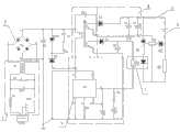
图1是本实用新型实施例电路原理框图。Fig. 1 is the functional block diagram of the circuit of the embodiment of the utility model.
图中:1、EMC和浪涌电流控制电路;2、一次整流和滤波电路;3、单端反激式DC/DC功率变换器;4、二次整流和滤波电路;5、快速充电电路;6、电池;7、信号采样及保护电路。In the figure: 1. EMC and surge current control circuit; 2. Primary rectification and filter circuit; 3. Single-ended flyback DC/DC power converter; 4. Secondary rectification and filter circuit; 5. Fast charging circuit; 6. Battery; 7. Signal sampling and protection circuit.
具体实施方式Detailed ways
如图1所示,带保护电路的快速充电装置,至少包括:EMC和浪涌电流控制电路1、一次整流和滤波电路2、单端反激式DC/DC功率变换器3,二次整流和滤波电路4、快速充电电路5、信号采样及保护电路7,220V交流输入与EMC和浪涌电流控制电路1电连接,经EMC和浪涌电流控制电路1保护后再与一次整流和滤波电路2电连接,形成300V左右的直流电压,直流电压输出与单端反激式DC/DC功率变换器3电连接,经单端反激式DC/DC功率变换器3形成高频交流输出,高频交流输出与二次整流和滤波电路4电连接,由二次整流和滤波电路4与快速充电电路5电连接,形成所需的充电电流对充电回路电连接的电池6进行快速充电。As shown in Figure 1, the fast charging device with protection circuit at least includes: EMC and surge current control circuit 1, primary rectification and filtering circuit 2, single-ended flyback DC/DC power converter 3, secondary rectification and Filtering circuit 4, fast charging circuit 5, signal sampling and protection circuit 7, 220V AC input is electrically connected with EMC and inrush current control circuit 1, after being protected by EMC and inrush current control circuit 1, it is connected with primary rectification and filter circuit 2 Electrically connected to form a DC voltage of about 300V, the DC voltage output is electrically connected to the single-ended flyback DC/DC power converter 3, and a high-frequency AC output is formed through the single-ended flyback DC/DC power converter 3, and the high-frequency The AC output is electrically connected to the secondary rectification and filtering circuit 4, and the secondary rectification and filtering circuit 4 is electrically connected to the fast charging circuit 5 to form the required charging current to quickly charge the battery 6 electrically connected to the charging circuit.
快速充电电路5回路与信号采样及保护电路7电连接,信号采样及保护电路7和单端反激式DC/DC功率变换器3共同构成具有过流、过压、过热和欠压保护的快速充电电路,单端反激式DC/DC功率变换器3中的调节变压器T2有两组次级输出,第一组次级输出通过第二级整流电路后作为充电电路,供电池6充电使用。第二组次级输出通过第三级整流电路后通过采样电路与PWM控制器TOP245的控制端电连接构成充电电路的过流、过压、过热和欠压保护电路,采样电路主要由光电耦合器、充电回路取样电路构成,充电回路取样电路是由稳压管、限流电阻R5、电阻R6和光电耦合器的发光管串接构成,充电回路取样电路并接在充电电路的输出端,光电耦合器的光电接收管的发射极与PWM控制器TOP245的控制端C端电连接,TOP245的控制端C端与TOP245的F端短路连接,连接后与地电压之间并接有电阻R4和电容C7的串接回路,电阻R4和电容C7的串接回路并接一电容C8。调节变压器T2的初级一端与一次整流和滤波电路2的输出正端电连接,另一端与PWM控制器TOP245的D端电连接,在一次整流和滤波电路2的输出正端和PWM控制器TOP245的D端串接有稳压管和反相连接的二极管D3,稳压管和反相连接的二极管D3连接点与一次整流和滤波电路2的输出正端由电阻R2和电容C3串联连接接的阻容回路。The fast charging circuit 5 loop is electrically connected to the signal sampling and protection circuit 7, and the signal sampling and protection circuit 7 and the single-ended flyback DC/DC power converter 3 together form a fast charging circuit with overcurrent, overvoltage, overheating and undervoltage protection. Charging circuit, the regulating transformer T2 in the single-ended flyback DC/DC power converter 3 has two sets of secondary outputs, the first set of secondary outputs passes through the second stage rectifier circuit and is used as a charging circuit for charging the battery 6 . The secondary output of the second group passes through the third-stage rectifier circuit and then is electrically connected to the control terminal of the PWM controller TOP245 through the sampling circuit to form the overcurrent, overvoltage, overheating and undervoltage protection circuit of the charging circuit. The sampling circuit is mainly composed of a photocoupler 1. The charging circuit sampling circuit is composed of a charging circuit sampling circuit. The charging circuit sampling circuit is composed of a voltage regulator tube, a current limiting resistor R5, a resistor R6 and a light-emitting tube of a photocoupler connected in series. The charging circuit sampling circuit is connected to the output of the charging circuit. The photoelectric coupling The emitter of the photoelectric receiver tube is electrically connected to the control terminal C of the PWM controller TOP245, and the control terminal C of the TOP245 is short-circuited to the F terminal of the TOP245. After the connection, a resistor R4 and a capacitor C7 are connected in parallel with the ground voltage The series connection circuit of the resistor R4 and the capacitor C7 is connected with a capacitor C8. One end of the primary side of the regulating transformer T2 is electrically connected to the output positive end of the primary rectification and filter circuit 2, and the other end is electrically connected to the D end of the PWM controller TOP245, and the output positive end of the primary rectification and filter circuit 2 is connected to the PWM controller TOP245. The terminal D is connected in series with a voltage regulator tube and a diode D3 connected in reverse phase, and the connection point of the voltage regulator tube and the diode D3 connected in reverse phase is connected to the positive output terminal of the primary rectification and filter circuit 2 through a resistor R2 and a capacitor C3 connected in series. capacity loop.
在调节变压器T2的第一组次级输出与初级一端有反馈电容C4,选用2.2nF/1kV。在快速充电电路的输出端有供充电电池充电的两个正负极接点,其中负极接点与负极之间有取样电阻R6,负极接点与取样电阻R6的电连接点通过二极管D2和电阻R3与充电回路取样电路回路电连接。There is a feedback capacitor C4 at the primary side of the first group of secondary outputs of the regulating transformer T2, which is 2.2nF/1kV. At the output end of the fast charging circuit, there are two positive and negative contacts for charging the rechargeable battery. There is a sampling resistor R6 between the negative contact and the negative pole. The loop sampling circuit is electrically connected to the loop.
本实用新型中,由充电电路负载引起的电流、电压变化或环境引起的电流、电压变化通过反馈到TOP245的控制端C,由TOP245调节变压器T2的振荡频率达到稳流、稳压的目的。在TOP245的控制端C与负电源之间有小于10Ω的电阻和串接的电解电容,消除控制端C交流电压。In the utility model, the current and voltage changes caused by the charging circuit load or the current and voltage changes caused by the environment are fed back to the control terminal C of TOP245, and the oscillation frequency of the transformer T2 is adjusted by the TOP245 to achieve the purpose of steady current and voltage. Between the control terminal C of TOP245 and the negative power supply, there is a resistance less than 10Ω and an electrolytic capacitor connected in series to eliminate the AC voltage of the control terminal C.
Claims (6)
Priority Applications (1)
| Application Number | Priority Date | Filing Date | Title |
|---|---|---|---|
| CN2011203260869UCN202218052U (en) | 2011-09-01 | 2011-09-01 | Fast charging device with protection circuit |
Applications Claiming Priority (1)
| Application Number | Priority Date | Filing Date | Title |
|---|---|---|---|
| CN2011203260869UCN202218052U (en) | 2011-09-01 | 2011-09-01 | Fast charging device with protection circuit |
Publications (1)
| Publication Number | Publication Date |
|---|---|
| CN202218052Utrue CN202218052U (en) | 2012-05-09 |
Family
ID=46017279
Family Applications (1)
| Application Number | Title | Priority Date | Filing Date |
|---|---|---|---|
| CN2011203260869UExpired - LifetimeCN202218052U (en) | 2011-09-01 | 2011-09-01 | Fast charging device with protection circuit |
Country Status (1)
| Country | Link |
|---|---|
| CN (1) | CN202218052U (en) |
Cited By (4)
| Publication number | Priority date | Publication date | Assignee | Title |
|---|---|---|---|---|
| CN102315679A (en)* | 2011-09-01 | 2012-01-11 | 河南省交通科学技术研究院有限公司 | Rapid charging circuit with protection circuit |
| CN102709981A (en)* | 2012-06-07 | 2012-10-03 | 广州益维电动汽车有限公司 | Energy-lossless equalizing charging device for series lithium ion battery pack |
| CN109114686A (en)* | 2018-10-16 | 2019-01-01 | 陈小得 | Air purifier |
| CN109883801A (en)* | 2019-03-01 | 2019-06-14 | 蔡长征 | Clamping device for medical treatment detection device |
- 2011
- 2011-09-01CNCN2011203260869Upatent/CN202218052U/ennot_activeExpired - Lifetime
Cited By (5)
| Publication number | Priority date | Publication date | Assignee | Title |
|---|---|---|---|---|
| CN102315679A (en)* | 2011-09-01 | 2012-01-11 | 河南省交通科学技术研究院有限公司 | Rapid charging circuit with protection circuit |
| CN102315679B (en)* | 2011-09-01 | 2014-07-09 | 河南省交通科学技术研究院有限公司 | Rapid charging circuit with protection circuit |
| CN102709981A (en)* | 2012-06-07 | 2012-10-03 | 广州益维电动汽车有限公司 | Energy-lossless equalizing charging device for series lithium ion battery pack |
| CN109114686A (en)* | 2018-10-16 | 2019-01-01 | 陈小得 | Air purifier |
| CN109883801A (en)* | 2019-03-01 | 2019-06-14 | 蔡长征 | Clamping device for medical treatment detection device |
Similar Documents
| Publication | Publication Date | Title |
|---|---|---|
| CN207218340U (en) | A switch type constant current and constant voltage lithium battery charger | |
| CN101882879B (en) | Circuit converting constant current source to constant voltage source and light using same | |
| CN204761146U (en) | Bimodulus power supply | |
| WO2019095995A1 (en) | High-power portable electrical equipment and power supply controlling apparatus and method therefor | |
| CN102315679B (en) | Rapid charging circuit with protection circuit | |
| CN202218052U (en) | Fast charging device with protection circuit | |
| CN104735845A (en) | Efficient 60-W LED driving power source | |
| CN202424283U (en) | Charger based on single-chip three-end TOP22X integrated chip | |
| CN107749672A (en) | Collection system for energy conversion | |
| CN107294393A (en) | A kind of low cost and high reliability Yi nationality medicine production isolation type switch power | |
| CN102969783A (en) | Direct current uninterruptible power supply | |
| CN202513643U (en) | Starting-charging device | |
| CN110707945A (en) | Rectifier circuit, wireless charging device, power supply equipment and wireless charging system | |
| CN114759278B (en) | Battery charging method controlled by MCU | |
| CN103715748A (en) | Lithium battery charging circuit | |
| CN217427719U (en) | Multi-protocol quick charging circuit and device | |
| CN104836316B (en) | A kind of constant-current charging circuit of adjustable current | |
| CN104202882B (en) | A kind of efficient non-isolation LED drive circuit of low-power consumption small-power | |
| CN102843045B (en) | Starting and charging device | |
| CN104426173A (en) | Charging circuit | |
| CN202153656U (en) | Switch power supply charger | |
| CN101969707B (en) | A kind of lamp switching circuit of battery charger | |
| CN204089313U (en) | Discharge and recharge change-over circuit and battery charging and discharging management circuit | |
| CN105656116B (en) | A kind of constant-current charging circuit using floating ground formula | |
| CN104079053B (en) | Charger feedback circuit |
Legal Events
| Date | Code | Title | Description |
|---|---|---|---|
| C14 | Grant of patent or utility model | ||
| GR01 | Patent grant | ||
| CX01 | Expiry of patent term | ||
| CX01 | Expiry of patent term | Granted publication date:20120509 |