CN202217780U - Antenna and mobile terminal for short-distance wireless communication - Google Patents
Antenna and mobile terminal for short-distance wireless communicationDownload PDFInfo
- Publication number
- CN202217780U CN202217780UCN2011203179566UCN201120317956UCN202217780UCN 202217780 UCN202217780 UCN 202217780UCN 2011203179566 UCN2011203179566 UCN 2011203179566UCN 201120317956 UCN201120317956 UCN 201120317956UCN 202217780 UCN202217780 UCN 202217780U
- Authority
- CN
- China
- Prior art keywords
- antenna
- display screen
- outline
- mobile terminal
- accommodating area
- Prior art date
- Legal status (The legal status is an assumption and is not a legal conclusion. Google has not performed a legal analysis and makes no representation as to the accuracy of the status listed.)
- Expired - Lifetime
Links
- 238000004891communicationMethods0.000titleclaimsabstractdescription20
- 238000000034methodMethods0.000claimsdescription10
- 238000009713electroplatingMethods0.000claimsdescription6
- 238000007639printingMethods0.000claimsdescription6
- 238000004519manufacturing processMethods0.000abstractdescription4
- 238000005516engineering processMethods0.000description7
- 238000010586diagramMethods0.000description6
- 230000008878couplingEffects0.000description2
- 238000010168coupling processMethods0.000description2
- 238000005859coupling reactionMethods0.000description2
- 230000000694effectsEffects0.000description2
- 239000000463materialSubstances0.000description2
- 230000005540biological transmissionEffects0.000description1
- 230000007547defectEffects0.000description1
- 239000004744fabricSubstances0.000description1
- 238000012986modificationMethods0.000description1
- 230000004048modificationEffects0.000description1
Images


Landscapes
- Mobile Radio Communication Systems (AREA)
Abstract
Description
Translated fromChinese技术领域technical field
本实用新型涉及通信领域,具体涉及一种用于近距离无线通讯的天线及移动终端。The utility model relates to the communication field, in particular to an antenna and a mobile terminal for short-distance wireless communication.
背景技术Background technique
近场通信(Near Field Communication,NFC),又称近距离无线通信,是一种短距离的高频无线通信技术,允许电子设备之间进行非接触式点对点数据传输(在十厘米内)交换数据。这个技术由免接触式射频识别(RFID)演变而来,并向下兼容RFID,因此可以在移动设备、消费类电子产品、PC和智能控件工具间进行近距离无线通信,可以让消费者简单直观地交换信息、访问内容与服务。由于近场通讯具有天然的安全性,因此,NFC技术被认为在手机支付等领域具有很大的应用前景。Near Field Communication (NFC), also known as short-range wireless communication, is a short-range high-frequency wireless communication technology that allows non-contact point-to-point data transmission (within ten centimeters) between electronic devices to exchange data . This technology evolved from contactless radio frequency identification (RFID) and is backward compatible with RFID, so it can perform short-range wireless communication between mobile devices, consumer electronics, PCs and smart control tools, allowing consumers to simply and intuitively Exchange information, access content and services efficiently. Due to the natural security of near-field communication, NFC technology is considered to have great application prospects in fields such as mobile payment.
在现有方案与技术中,NFC天线常常采用独立FPC(柔性电路板)的形式来进行实现。例如,在FPC上走线,然后将FPC和走线一起粘贴在液晶显示屏上。这种方式的缺点很明显,势必需要单独的FPC组件来实现,同时,在组装生产时也需要增加工位来实现,一定程度上有损组装效率。In existing solutions and technologies, the NFC antenna is often implemented in the form of an independent FPC (flexible printed circuit board). For example, trace the wires on the FPC, and then paste the FPC and the wires together on the LCD screen. The disadvantage of this method is obvious, and it is bound to require a separate FPC component to realize it. At the same time, it also needs to increase the number of stations to realize it during assembly production, which will damage the assembly efficiency to a certain extent.
在现有方案与技术中,NFC天线也有采用导电透明膜而实现的NFC天线的形式。例如,使用一导电透明薄膜贴附在显示屏幕上,所述薄膜内部设置有一天线和NFC芯片。目前这种工艺和材料还不足以实现这种应用,这在一定程度上影响了这种方案的推广与应用,更重要的是,这种方式的加工成本较高。In existing solutions and technologies, the NFC antenna also has the form of an NFC antenna realized by using a conductive transparent film. For example, a conductive transparent film is attached to the display screen, and an antenna and an NFC chip are arranged inside the film. At present, this technology and materials are not enough to realize this application, which affects the promotion and application of this solution to a certain extent, and more importantly, the processing cost of this method is relatively high.
另外,不论是以前上哪种方案,都需要增加独立的附加组件来协助完成,如柔性电路板或导电薄膜,这就不可避免的造成成本的增加。In addition, regardless of the previous solution, it is necessary to add an independent additional component to assist in the completion, such as a flexible circuit board or a conductive film, which inevitably leads to an increase in cost.
实用新型内容Utility model content
本实用新型所要解决的技术问题在于提供一种用于近距离无线通讯的天线及移动终端,以克服现有的NFC天线的生产需要增加附件组件同时加工成本较高的缺陷。The technical problem to be solved by the utility model is to provide an antenna and a mobile terminal for short-distance wireless communication, so as to overcome the defect that the production of the existing NFC antenna needs to increase the accessory components and the processing cost is high.
为了解决上述问题,本实用新型提供了一种用于近距离无线通讯的天线,所述天线设置在显示屏幕的轮廓部分。In order to solve the above problems, the utility model provides an antenna for short-distance wireless communication, and the antenna is arranged on the outline of the display screen.
进一步地,所述天线设置于所述显示屏幕轮廓部分相应的容置区域中,采用印刷或电镀工艺固定。Further, the antenna is arranged in a corresponding accommodating area of the outline of the display screen, and fixed by printing or electroplating process.
进一步地,所述容置区域具有沟槽结构,所述天线置于所述沟槽结构中;或者,所述容置区域为平面结构,所述天线放置在所述平面结构上。Further, the accommodating area has a groove structure, and the antenna is placed in the groove structure; or, the accommodating area is a planar structure, and the antenna is placed on the planar structure.
进一步地,所述天线和所述容置区域的形状依据所述显示屏幕的轮廓的形状设置;所述容置区域设置于所述显示屏幕背面的轮廓部分、显示屏幕正面的轮廓部分或者显示屏幕中间层的轮廓部分。Further, the shapes of the antenna and the accommodating area are set according to the shape of the outline of the display screen; the accommodating area is set on the outline of the back of the display screen, the outline of the front of the display screen, or the display screen Outline part of the middle layer.
进一步地,所述天线在末端引出馈电点,作为与移动终端耦接的通讯接口。Further, the antenna leads out to a feeding point at the end to serve as a communication interface coupled with the mobile terminal.
为了解决上述问题,本实用新型还提供了一种移动终端,包括用于近距离无线通讯的天线及显示屏幕,所述天线设置在显示屏幕的轮廓部分。In order to solve the above problems, the utility model also provides a mobile terminal, including an antenna for short-distance wireless communication and a display screen, and the antenna is arranged on the outline of the display screen.
进一步地,所述天线设置于所述显示屏幕轮廓部分相应的容置区域中,采用印刷或电镀工艺固定。Further, the antenna is arranged in a corresponding accommodating area of the outline of the display screen, and fixed by printing or electroplating process.
进一步地,所述容置区域具有沟槽结构,所述天线置于所述沟槽结构中;或者,所述容置区域为平面结构,所述天线放置在所述平面结构上。Further, the accommodating area has a groove structure, and the antenna is placed in the groove structure; or, the accommodating area is a planar structure, and the antenna is placed on the planar structure.
进一步地,所述天线和所述容置区域的形状依据所述显示屏幕的轮廓的形状设置;所述容置区域设置于所述显示屏幕背面的轮廓部分、显示屏幕正面的轮廓部分或者显示屏幕中间层的轮廓部分。Further, the shapes of the antenna and the accommodating area are set according to the shape of the outline of the display screen; the accommodating area is set on the outline of the back of the display screen, the outline of the front of the display screen, or the display screen Outline part of the middle layer.
进一步地,所述天线在末端引出馈电点,作为与移动终端本体耦接的通讯接口。Further, the antenna leads out to a feeding point at the end to serve as a communication interface coupled with the mobile terminal body.
1)应用本实用新型,不需要附件组件,节省了成本,同时也提升了组装生产的效率。1) Application of the utility model does not require accessory components, which saves costs and improves the efficiency of assembly and production.
2)本实用新型的实现是在现有工艺与材质能充分满足的前提下实现,所以,它的推广与应用范围是极其广泛。2) The realization of the utility model is realized under the premise that the existing technology and materials can be fully satisfied, so its promotion and application range are extremely wide.
附图说明Description of drawings
此处所说明的附图用来提供对本实用新型的进一步理解,构成本申请的一部分,本实用新型的示意性实施例及其说明用于解释本实用新型,并不构成对本实用新型的不当限定。在附图中:The drawings described here are used to provide a further understanding of the utility model and constitute a part of the application. The schematic embodiments of the utility model and their descriptions are used to explain the utility model and do not constitute improper limitations to the utility model. In the attached picture:
图1是本实用新型实施例的移动终端示意图;Fig. 1 is the schematic diagram of the mobile terminal of the utility model embodiment;
图2是本实用新型实施例的NFC天线的走线以及NFC天线和显示屏幕的结构关系示意图;Fig. 2 is a schematic diagram of the wiring of the NFC antenna and the structural relationship between the NFC antenna and the display screen of the embodiment of the present invention;
图3是本实用新型实施例的显示屏幕背面的结构示意图;Fig. 3 is a schematic structural view of the back of the display screen according to the embodiment of the present invention;
图4是本实用新型实施例的NFC天线的馈电点的结构示意图。Fig. 4 is a schematic structural diagram of a feeding point of an NFC antenna according to an embodiment of the present invention.
具体实施方式Detailed ways
以下将配合附图及实施例来详细说明本实用新型的实施方式,藉此对本实用新型如何应用技术手段来解决技术问题并达成技术功效的实现过程能充分理解并据以实施。The implementation of the utility model will be described in detail below in conjunction with the accompanying drawings and examples, so that the implementation process of how the utility model uses technical means to solve technical problems and achieve technical effects can be fully understood and implemented accordingly.
本实用新型的核心在于:NFC天线的多个线圈设置在显示屏幕的轮廓部分,不需要增加如柔性电路板或导电薄膜的其他组件。The core of the present invention is that multiple coils of the NFC antenna are arranged on the outline of the display screen, without adding other components such as flexible circuit boards or conductive films.
下面以一实施例对本实用新型的移动终端作进一步说明。The mobile terminal of the present invention will be further described with an embodiment below.
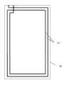
如图1所示,是本实用新型实施例的移动终端示意图,所述移动终端包括:移动终端本体30、NFC天线(图中未示出)和显示屏幕20。在本实施例中,所述显示屏幕20为一触摸屏幕。As shown in FIG. 1 , it is a schematic diagram of a mobile terminal according to an embodiment of the present invention. The mobile terminal includes: a
如图2所示,为图1中移动终端的显示屏幕的背面,其示出了NFC天线的走线以及NFC天线和显示屏幕20的结构关系。NFC天线包括:多个线圈10,所述线圈10设置在显示屏幕20的轮廓部分。As shown in FIG. 2 , it is the back side of the display screen of the mobile terminal in FIG. 1 , which shows the routing of the NFC antenna and the structural relationship between the NFC antenna and the
如图3所示,是本实用新型实施例的显示屏幕的背面的结构示意图。所述线圈10设置于所述显示屏幕20的轮廓部分相应的容置区域200中,采用印刷或电镀工艺固定。优选的,所述容置区域200具有沟槽结构,所述线圈置于所述沟槽结构中。另外,在另一实施例中,所述容置区域200也可以是为工艺加工预留的平面区域,所述线圈放置在所述平面结构上,本实用新型对此不进行限制。As shown in FIG. 3 , it is a structural schematic view of the back of the display screen according to the embodiment of the present invention. The
还需要说明一点,以上实施例是以NFC天线在显示屏幕的背面(即显示屏幕与移动终端本体相连的一面)走线来进行说明的,但是本实用新型并不限于此。如果NFC走线足够美观,配合好的移动终端外形,NFC天线在显示屏幕的正面(即显示屏幕暴露在外呈现显示效果的一面)走线也是可以的,此时,如上例所述的容置区域200的沟槽结构和平面结构也同样适用于本例。另外,因为显示屏幕是多层结构压合成型,所以NFC天线还可以在显示屏幕的中间层走线。One more thing needs to be explained, the above embodiment is described by routing the NFC antenna on the back of the display screen (that is, the side where the display screen is connected to the mobile terminal body), but the present invention is not limited thereto. If the NFC wiring is beautiful enough and matches the appearance of a good mobile terminal, it is also possible to route the NFC antenna on the front of the display screen (that is, the side where the display screen is exposed to show the display effect). At this time, the accommodating area as described in the above example The trench structure and planar structure of 200 are also applicable to this example. In addition, because the display screen is laminated with a multi-layer structure, the NFC antenna can also be routed in the middle layer of the display screen.
如图4所示,是本实用新型实施例的NFC天线的馈电点的结构示意图。所述线圈10在末端引出馈电点100,作为NFC天线与移动终端本体30耦接的通讯接口。需要说明的是,为了配合与移动终端本体30的连接需要,馈电点100的位置、形状、结构根据移动终端本体30、NFC天线及显示屏幕的实际结构关系来设置,并不限于图4中所述的位置。As shown in FIG. 4 , it is a schematic structural diagram of the feeding point of the NFC antenna of the embodiment of the present invention. The end of the
下面再以一实施例对本实用新型的NFC天线作进一步说明。Next, an embodiment will be used to further illustrate the NFC antenna of the present invention.
如图4所示,为NFC天线的走线以及NFC天线和显示屏幕20的结构关系示意图。NFC天线包括:多个线圈10,所述线圈10设置在显示屏幕20的轮廓部分。所述线圈10在末端引出馈电点100,作为NFC天线与移动终端本体耦接的通讯接口。需要说明的是,为了配合与移动终端本体30的连接需要,馈电点100的位置、形状、结构根据移动终端本体30、NFC天线及显示屏幕的实际结构关系来设置,并不限于图4中所述的位置。As shown in FIG. 4 , it is a schematic diagram of the wiring of the NFC antenna and the structural relationship between the NFC antenna and the
如图3所示,是本实用新型实施例的显示屏幕的背面的结构示意图。所述线圈10设置于所述显示屏幕20的轮廓部分相应的容置区域200中,采用印刷或电镀工艺固定。容置区域200可以设置于所述显示屏幕的表面(即正面或者背面)的轮廓部分。优选的,所述容置区域200具有沟槽结构,所述线圈10置于所述沟槽结构中。另外,在另一实施例中,所述容置区域200也可以是为工艺加工预留的平面区域,所述线圈放置在所述平面结构上,本实用新型对此不进行限制。As shown in FIG. 3 , it is a structural schematic view of the back of the display screen according to the embodiment of the present invention. The
另外,所述容置区域除了可以设置于所述显示屏幕的表面(即正面或者背面)的轮廓部分,还可以设置在显示屏幕中间层的轮廓部分,所述线圈10在在显示屏幕中间层排布走线。In addition, the accommodating area can be set not only on the outline of the surface (ie front or back) of the display screen, but also on the outline of the middle layer of the display screen, and the
NFC走线一般排布在所述显示屏幕20的轮廓,因此,所述线圈10和所述容置区域200的形状依据所述显示屏幕20的轮廓的形状设置。所述显示屏幕20的轮廓一般大致为矩形、规则的圆形、椭圆形等,因此,所述线圈10和所述容置区域200的形状大致为矩形、环形等等。如图1和图2所示,为矩形形状,但是本实用新型并不限于此。NFC wires are generally arranged on the outline of the
述说明示出并描述了本实用新型的若干优选实施例,但如前所述,应当理解本实用新型并非局限于本文所披露的形式,不应看作是对其他实施例的排除,而可用于各种其他组合、修改和环境,并能够在本文所述实用新型构想范围内,通过上述教导或相关领域的技术或知识进行改动。而本领域人员所进行的改动和变化不脱离本实用新型的精神和范围,则都应在本实用新型所附权利要求的保护范围内。The description shows and describes several preferred embodiments of the present utility model, but as mentioned above, it should be understood that the present utility model is not limited to the form disclosed herein, and should not be regarded as excluding other embodiments, but can be used in Various other combinations, modifications and circumstances, and can be modified by the above teachings or skills or knowledge in related fields within the scope of the utility model concept described herein. However, changes and changes made by those skilled in the art do not depart from the spirit and scope of the utility model, and should all be within the protection scope of the appended claims of the utility model.
Claims (10)
Translated fromChinesePriority Applications (1)
| Application Number | Priority Date | Filing Date | Title |
|---|---|---|---|
| CN2011203179566UCN202217780U (en) | 2011-08-29 | 2011-08-29 | Antenna and mobile terminal for short-distance wireless communication |
Applications Claiming Priority (1)
| Application Number | Priority Date | Filing Date | Title |
|---|---|---|---|
| CN2011203179566UCN202217780U (en) | 2011-08-29 | 2011-08-29 | Antenna and mobile terminal for short-distance wireless communication |
Publications (1)
| Publication Number | Publication Date |
|---|---|
| CN202217780Utrue CN202217780U (en) | 2012-05-09 |
Family
ID=46017015
Family Applications (1)
| Application Number | Title | Priority Date | Filing Date |
|---|---|---|---|
| CN2011203179566UExpired - LifetimeCN202217780U (en) | 2011-08-29 | 2011-08-29 | Antenna and mobile terminal for short-distance wireless communication |
Country Status (1)
| Country | Link |
|---|---|
| CN (1) | CN202217780U (en) |
Cited By (6)
| Publication number | Priority date | Publication date | Assignee | Title |
|---|---|---|---|---|
| CN103779647A (en)* | 2012-10-23 | 2014-05-07 | 三星电子株式会社 | NFC antenna for portable device |
| CN103944614A (en)* | 2014-03-21 | 2014-07-23 | 深圳市汇顶科技股份有限公司 | Near field communication system and terminals |
| CN104242962A (en)* | 2013-06-18 | 2014-12-24 | 联想(北京)有限公司 | Method for receiving signal to be processed and receiver |
| CN105357339A (en)* | 2015-10-20 | 2016-02-24 | 努比亚技术有限公司 | Antenna |
| EP3014380B1 (en)* | 2013-09-23 | 2019-07-17 | Apple Inc. | Electronic component embedded in ceramic material |
| CN114284691A (en)* | 2020-09-28 | 2022-04-05 | 广东小天才科技有限公司 | NFC antenna structure and mobile terminal |
- 2011
- 2011-08-29CNCN2011203179566Upatent/CN202217780U/ennot_activeExpired - Lifetime
Cited By (10)
| Publication number | Priority date | Publication date | Assignee | Title |
|---|---|---|---|---|
| CN103779647A (en)* | 2012-10-23 | 2014-05-07 | 三星电子株式会社 | NFC antenna for portable device |
| CN104242962A (en)* | 2013-06-18 | 2014-12-24 | 联想(北京)有限公司 | Method for receiving signal to be processed and receiver |
| CN104242962B (en)* | 2013-06-18 | 2017-06-27 | 联想(北京)有限公司 | A kind of method of reseptance and receiver of pending signal |
| EP3014380B1 (en)* | 2013-09-23 | 2019-07-17 | Apple Inc. | Electronic component embedded in ceramic material |
| CN103944614A (en)* | 2014-03-21 | 2014-07-23 | 深圳市汇顶科技股份有限公司 | Near field communication system and terminals |
| US10201028B2 (en) | 2014-03-21 | 2019-02-05 | Shenzhen GOODIX Technology Co., Ltd. | Near-field communication method and terminal |
| CN105357339A (en)* | 2015-10-20 | 2016-02-24 | 努比亚技术有限公司 | Antenna |
| WO2017067462A1 (en)* | 2015-10-20 | 2017-04-27 | 努比亚技术有限公司 | Antenna |
| CN105357339B (en)* | 2015-10-20 | 2018-08-21 | 努比亚技术有限公司 | A kind of antenna |
| CN114284691A (en)* | 2020-09-28 | 2022-04-05 | 广东小天才科技有限公司 | NFC antenna structure and mobile terminal |
Similar Documents
| Publication | Publication Date | Title |
|---|---|---|
| CN202068693U (en) | Shell of terminal front shell and terminal | |
| CN202217780U (en) | Antenna and mobile terminal for short-distance wireless communication | |
| CN204790936U (en) | Integration has touch screen and electronic equipment of NFCRFID antenna | |
| CN203521617U (en) | Flexible wearable near-field communication and wireless charging antenna and terminal | |
| CN107591616B (en) | Coil type based antenna and method of forming the same | |
| CN103715501A (en) | NFC antenna, mobile terminal and manufacturing method of NFC antenna | |
| CN103050779B (en) | A kind of NFC antenna and manufacture method thereof and a kind of NFC communication equipment | |
| TW201624826A (en) | Hybrid-type NFC antenna and the electronic device thereof | |
| CN204947083U (en) | A kind of NFC antenna structure of metal back cover | |
| CN104681917B (en) | Antenna structure with double coils | |
| CN204741068U (en) | A smart phone and its parallel multi-turn NFC antenna | |
| CN204741075U (en) | A smart phone and its NFC antenna with single loop and auxiliary loop | |
| CN205017754U (en) | Circuit board components and electronic equipment | |
| CN106910985A (en) | Application of the novel laminated parallel-connection structure NFC antenna in mobile terminal | |
| CN203423688U (en) | Device having functions of near and far field wireless communication and wireless charging | |
| CN203039106U (en) | NFC (near field communication) antenna and NFC device | |
| CN203800175U (en) | NFC antenna module | |
| CN218825356U (en) | Touch screen structure, touch screen and display device integrating near-field communication antenna | |
| CN204407465U (en) | NFC antenna assembled fixture | |
| CN203481388U (en) | Multiplexing antenna used for mobile terminal | |
| CN205646168U (en) | NFC antenna module and terminal equipment | |
| CN106329077A (en) | Double-sided board wire-based NFC (Near Field Communication) antenna and electronic device | |
| CN104124990A (en) | Terminal equipment with near field communication and wireless charging functions | |
| WO2012122743A1 (en) | Mobile terminal with radio frequency identification function | |
| CN203760630U (en) | Nfc antenna |
Legal Events
| Date | Code | Title | Description |
|---|---|---|---|
| C14 | Grant of patent or utility model | ||
| GR01 | Patent grant | ||
| CX01 | Expiry of patent term | Granted publication date:20120509 | |
| CX01 | Expiry of patent term |