CN202199129U - lighting glasses - Google Patents
lighting glassesDownload PDFInfo
- Publication number
- CN202199129U CN202199129UCN2011900000016UCN201190000001UCN202199129UCN 202199129 UCN202199129 UCN 202199129UCN 2011900000016 UCN2011900000016 UCN 2011900000016UCN 201190000001 UCN201190000001 UCN 201190000001UCN 202199129 UCN202199129 UCN 202199129U
- Authority
- CN
- China
- Prior art keywords
- temple arm
- light source
- arm element
- light
- temple
- Prior art date
- Legal status (The legal status is an assumption and is not a legal conclusion. Google has not performed a legal analysis and makes no representation as to the accuracy of the status listed.)
- Expired - Lifetime
Links
- 239000011521glassSubstances0.000titleclaimsdescription112
- 239000000463materialSubstances0.000claimsdescription52
- 230000007246mechanismEffects0.000claimsdescription30
- 230000008859changeEffects0.000claimsdescription7
- 238000005286illuminationMethods0.000claimsdescription7
- 230000003287optical effectEffects0.000claimsdescription6
- 238000001914filtrationMethods0.000claimsdescription3
- 239000004020conductorSubstances0.000claimsdescription2
- 238000013519translationMethods0.000claimsdescription2
- 239000011469building brickSubstances0.000claims2
- 230000003213activating effectEffects0.000claims1
- 208000002925dental cariesDiseases0.000claims1
- 238000009792diffusion processMethods0.000claims1
- 238000009434installationMethods0.000claims1
- 238000000576coating methodMethods0.000description31
- 239000011248coating agentSubstances0.000description22
- ORQBXQOJMQIAOY-UHFFFAOYSA-NnobeliumChemical compound[No]ORQBXQOJMQIAOY-UHFFFAOYSA-N0.000description20
- 238000013459approachMethods0.000description13
- 230000000903blocking effectEffects0.000description13
- 230000001681protective effectEffects0.000description11
- 210000003128headAnatomy0.000description10
- 230000000149penetrating effectEffects0.000description9
- 238000010276constructionMethods0.000description8
- PXHVJJICTQNCMI-UHFFFAOYSA-NNickelChemical compound[Ni]PXHVJJICTQNCMI-UHFFFAOYSA-N0.000description4
- 239000000853adhesiveSubstances0.000description3
- 230000001070adhesive effectEffects0.000description3
- 230000009969flowable effectEffects0.000description3
- 229910052751metalInorganic materials0.000description3
- 239000002184metalSubstances0.000description3
- 239000004033plasticSubstances0.000description3
- BQCADISMDOOEFD-UHFFFAOYSA-NSilverChemical compound[Ag]BQCADISMDOOEFD-UHFFFAOYSA-N0.000description2
- 210000005069earsAnatomy0.000description2
- 210000003811fingerAnatomy0.000description2
- 230000004313glareEffects0.000description2
- RSNHXDVSISOZOB-UHFFFAOYSA-Nlithium nickelChemical compound[Li].[Ni]RSNHXDVSISOZOB-UHFFFAOYSA-N0.000description2
- WUALQPNAHOKFBR-UHFFFAOYSA-Nlithium silverChemical compound[Li].[Ag]WUALQPNAHOKFBR-UHFFFAOYSA-N0.000description2
- 238000000034methodMethods0.000description2
- 230000003278mimic effectEffects0.000description2
- 238000012986modificationMethods0.000description2
- 230000004048modificationEffects0.000description2
- 229910052759nickelInorganic materials0.000description2
- 239000003973paintSubstances0.000description2
- 230000035515penetrationEffects0.000description2
- 239000005336safety glassSubstances0.000description2
- 229910052709silverInorganic materials0.000description2
- 239000004332silverSubstances0.000description2
- 210000003813thumbAnatomy0.000description2
- 239000012780transparent materialSubstances0.000description2
- 239000002253acidSubstances0.000description1
- NIXOWILDQLNWCW-UHFFFAOYSA-Nacrylic acid groupChemical groupC(C=C)(=O)ONIXOWILDQLNWCW-UHFFFAOYSA-N0.000description1
- 230000000712assemblyEffects0.000description1
- 238000000429assemblyMethods0.000description1
- 230000003796beautyEffects0.000description1
- 238000005452bendingMethods0.000description1
- 230000004397blinkingEffects0.000description1
- 238000009500colour coatingMethods0.000description1
- 230000000295complement effectEffects0.000description1
- 239000012141concentrateSubstances0.000description1
- 230000003750conditioning effectEffects0.000description1
- 238000012937correctionMethods0.000description1
- 230000000994depressogenic effectEffects0.000description1
- 238000005553drillingMethods0.000description1
- 230000000694effectsEffects0.000description1
- 230000003203everyday effectEffects0.000description1
- 230000004438eyesightEffects0.000description1
- 210000005224forefingerAnatomy0.000description1
- 230000003760hair shineEffects0.000description1
- 239000011810insulating materialSubstances0.000description1
- 239000004922lacquerSubstances0.000description1
- 239000002650laminated plasticSubstances0.000description1
- 239000010410layerSubstances0.000description1
- 239000007769metal materialSubstances0.000description1
- 238000000465mouldingMethods0.000description1
- 239000013307optical fiberSubstances0.000description1
- 230000037361pathwayEffects0.000description1
- 230000005043peripheral visionEffects0.000description1
- 239000004417polycarbonateSubstances0.000description1
- 229920000515polycarbonatePolymers0.000description1
- 238000002310reflectometryMethods0.000description1
- 230000004044responseEffects0.000description1
- 238000007789sealingMethods0.000description1
- 238000000926separation methodMethods0.000description1
- 230000007704transitionEffects0.000description1
- 239000002966varnishSubstances0.000description1
- 230000000007visual effectEffects0.000description1
Images


Classifications
- G—PHYSICS
- G02—OPTICS
- G02C—SPECTACLES; SUNGLASSES OR GOGGLES INSOFAR AS THEY HAVE THE SAME FEATURES AS SPECTACLES; CONTACT LENSES
- G02C11/00—Non-optical adjuncts; Attachment thereof
- G02C11/04—Illuminating means
- F—MECHANICAL ENGINEERING; LIGHTING; HEATING; WEAPONS; BLASTING
- F21—LIGHTING
- F21L—LIGHTING DEVICES OR SYSTEMS THEREOF, BEING PORTABLE OR SPECIALLY ADAPTED FOR TRANSPORTATION
- F21L4/00—Electric lighting devices with self-contained electric batteries or cells
Landscapes
- Physics & Mathematics (AREA)
- Health & Medical Sciences (AREA)
- General Physics & Mathematics (AREA)
- Ophthalmology & Optometry (AREA)
- Optics & Photonics (AREA)
- Engineering & Computer Science (AREA)
- General Engineering & Computer Science (AREA)
- Eyeglasses (AREA)
- Arrangement Of Elements, Cooling, Sealing, Or The Like Of Lighting Devices (AREA)
Abstract
Description
Translated fromChinese相关申请的交叉引用Cross References to Related Applications
本申请是2007年11月16日提交的美国申请11/941,558的部分连续申请,其是2006年5月17日提交的在先国际申请PCT/US2006/018968的部分连续申请,其要求以2005年5月17日提交的美国临时申请60/681,852和2006年5月2日提交的美国临时申请60/746,217作为优先权,这些申请全部内容都引入在此作为参考。本申请还是2010年9月30日提交的美国申请12/895,456的部分连续申请,该申请要求以2009年9月30日提交的美国临时申请61/247,243作为优先权,这两个申请的全部内容都引入在此作为参考。本申请还要求以2010年2月10日提交的美国临时申请61/303,212作为优先权,该申请全部内容引入在此作为参考。 This application is a continuation-in-part of U.S. application 11/941,558, filed November 16, 2007, which is a continuation-in-part of earlier International Application PCT/US2006/018968, filed May 17, 2006, which claims to be filed in 2005 Priority is given to US
技术领域technical field
本实用新型涉及免提发光装置,更特别地涉及照明眼镜。 The utility model relates to a hands-free lighting device, more particularly to lighting glasses. the
背景技术Background technique
通常个人在完成任务时需要光源对区域进行照明或为了视界需要沿向外方向指向的光源。一种选择是持手电筒,但这种发光装置经常比较笨重并经常因为必须手持手电筒而影响任务的完成。因此,经常采用免提发光装置,因为需要照明的个人无需手持光源。常见类型的免提发光装置包括安装在头盔或眼镜上的光源。 Often an individual needs a light source to illuminate an area while performing a task or a light source pointing in an outward direction for viewing. One option is to carry a flashlight, but such lighting devices are often cumbersome and often interfere with task completion by having to hold the flashlight. As a result, hands-free lighting fixtures are often employed because the individual needing the illumination does not have to hold the light source in hand. Common types of hands-free lighting include light sources mounted on helmets or glasses. the
眼镜上的光源通常包括在眼镜的横撑架或边撑上以向佩戴者提供向前照明的光源(可以是LED)安装结构。在这样的构造中,通常采用发光眼镜提供定向或聚焦光,使得佩戴者正前方例如距他们的眼镜6-24英寸的区域可以得到照亮以完成例如阅读标准尺寸印刷品的任务。对于其他活动,例如夜晚散步、露营或日常使用,会需要甚至个人前方的其他照明区域。然而,之前被构造成为了多种目的中的一些目的提供免提发光装置的发光眼镜通常较重、体积较大、不方便和/或因发光装置在照明眼镜上位置突出而使外观难看。 Light sources on eyeglasses typically include a light source (which may be an LED) mounting structure on the crosspiece or temple of the eyewear to provide forward illumination to the wearer. In such configurations, light-emitting glasses are typically employed to provide directed or focused light so that an area directly in front of the wearer, eg, 6-24 inches from their glasses, can be illuminated for tasks such as reading standard sized printed matter. For other activities, such as night walks, camping or everyday use, additional illuminated areas even in front of the individual may be required. However, previously illuminated eyewear configured to provide hands-free lighting for some of a variety of purposes has typically been heavy, bulky, inconvenient, and/or unsightly due to the protruding location of the light on the illuminated eyewear. the
这方面,一些之前的发光眼镜具有紧固在眼镜上独立且体积较大的发光组件,例如在授予Murphy等人的美国专利No.5,541,767、授予Wu的美国专利No.4,959,760和授予Perl的美国专利No.3,769,663中的公开。这些眼镜较重和/或体积较大,从而使使用者佩戴不便。此外,这些之前的发光眼镜将发光组件显著安装在眼镜上或在其中包含用于发光的电子部件,使得当佩戴眼镜时发光组件或电子部件的存在在视觉上很突出,从而使眼镜的外观变差。 In this regard, some prior light-emitting glasses have separate and bulky light-emitting assemblies fastened to the glasses, such as in U.S. Patent No. 5,541,767 to Murphy et al., U.S. Patent No. 4,959,760 to Wu, and U.S. Patent No. 4,959,760 to Perl. Disclosure in No. 3,769,663. These glasses are heavy and/or bulky, making it inconvenient for the user to wear them. In addition, these previous light-emitting glasses significantly mounted a light-emitting component on the glasses or included electronic components for lighting therein, so that the presence of the light-emitting component or electronic components was visually prominent when the glasses were worn, thereby changing the appearance of the glasses. Difference. the
实用新型内容Utility model content
提供一种照明眼镜,在佩戴眼镜时其将光引导到使用者前方。 Illuminated eyewear is provided that directs light forward of a user when the eyewear is worn. the
本实用新型的方面在于提供一种照明眼镜,包括:前横向延伸的横撑架部分;一对边撑臂部分,在使用构造下边撑臂元件从前横撑架部分向后延伸;在使用构造下横撑架部分的前框架部分靠近所述一对边撑臂部分;靠近外前框架部分安装在边撑臂部分或横撑架部分上的光源;以及前框架部分中的每个的贯穿部分,其定向成在边撑臂部分处于使用构造时在光源的前方,贯穿部分被构造成使从每个光源投射的光可以穿过前框架部分投射在横撑架部分的前方。 An aspect of the present invention is to provide a kind of illuminating glasses, comprising: a cross brace part extending transversely in the front; a pair of temple arm parts, the temple arm elements extend rearwardly from the front cross brace part in the use configuration; a front frame portion of the cross brace portion adjacent to the pair of temple arm portions; a light source mounted on the temple arm portion or the cross brace portion adjacent to the outer front frame portion; and a penetrating portion of each of the front frame portions, They are oriented in front of the light sources when the temple arm portions are in the use configuration and the through portions are configured so that light projected from each light source can pass through the front frame portion and project in front of the cross brace portion. the
如上所述的照明眼镜,贯穿部分可以包括在前框架部分上的空腔以及装配在空腔上的盖,其为预定材料的以使从每个光源投射的光可以从中穿过。盖的预定材料是透明或半透明的,以使从光源投射的光可以在不折射的情况下从中穿过。盖的预定材料可以是扩散材料、折射材料、彩色滤光片、波长滤光片或着色的材料中的一种。横撑架部分和盖可以包括相互平齐的相应前表面。横撑架部分可以包括横撑架元件,边撑臂部分包括边撑臂元件,以及边撑臂元件中的每个与横撑架元件之间的枢转连接件用于使边撑臂元件在使用构造与存放构造之间枢转,在存放构造中边撑臂元件靠近横撑架元件横向延伸。贯穿部分可以包括向后开口的孔,边撑臂元件中的每个包括前表面,并且光源被安装成包括其前部,该前部向前突出超过边撑臂元件的前表面,使得在边撑臂元件处于使用构造时,光源的前部延伸到所述孔内。 As described above in the lighting glasses, the penetrating portion may include a cavity on the front frame portion and a cover fitted on the cavity, which is of a predetermined material so that light projected from each light source can pass therethrough. The predetermined material of the cover is transparent or translucent so that light projected from the light source can pass therethrough without being refracted. The predetermined material of the cover may be one of a diffusing material, a refractive material, a color filter, a wavelength filter, or a colored material. The cross brace portion and the cover may include respective front surfaces that are flush with each other. The cross brace portion may include a cross brace member, the temple arm portion may include a temple arm member, and a pivotal connection between each of the temple arm members and the cross brace member for allowing the temple arm member to The temple arm member pivots between a use configuration and a storage configuration in which the temple arm member extends laterally adjacent the cross brace member. The through portion may include a hole opening rearwardly, each of the temple arm elements includes a front surface, and the light source is mounted to include a front portion thereof protruding forward beyond the front surface of the temple arm elements such that The front of the light source extends into said aperture when the brace member is in the use configuration. the
如上所述的照明眼镜,还可以包括靠近光源从边撑臂元件的前表面向前延伸的阻光元件,其用于在边撑臂元件处于使用构造时阻止意外光穿过边撑臂元件与横撑架元件之间的横向向内间隙投射。阻光元件可以包括至少部分地包绕光源的 弧形壁。贯穿部分向后开口的孔可以包括在每个前框架部分上的通孔,其具有用于在其中容纳阻光元件的扩大后孔部分。 Illuminated eyewear as described above, further comprising a light blocking member extending forwardly from the front surface of the temple member proximate to the light source for preventing accidental light from passing through the temple member and the temple member when the temple member is in the use configuration. Lateral inward gap projection between cross brace elements. The light blocking element may comprise a curved wall at least partially surrounding the light source. The through-portion rearwardly opening aperture may comprise a through-hole on each front frame portion having an enlarged rear aperture portion for receiving the light blocking element therein. the
如上所述的照明眼镜,还可以包括从横撑架元件的前框架部分向后延伸并在边撑臂元件处于使用构造时横向靠近光源的阻光元件,其在边撑臂元件处于使用构造时用于阻止意外光穿过边撑臂元件与横撑架元件之间的横向向内间隙投射。光源可以容纳在横撑架部分中的空腔内。贯穿部分可以包括在光源前方安装至横撑架部分的半透明材料层。横撑架部分可以包括具有内基本层和后层的层压结构,所述空腔处于内基本层中并在其后端由后层覆盖。横撑架部分的层压结构还可以包括前层并且贯穿部分包括在光源前方的前层的半透明部分。光源可以包括容纳在空腔内的三个光源,这些空腔分别在其前框架部分和中间,并且容纳在前框架部分的空腔内的光源向内且向下倾斜,容纳在中间空腔内的光源不倾斜。光源和贯穿部分可以分别向内和向下倾斜以对照明眼镜前方的可视区域进行照明。 Illuminated eyewear as described above, further comprising a light blocking member extending rearwardly from the front frame portion of the cross member and laterally adjacent to the light source when the temple member is in the use configuration, when the temple member is in the use configuration Used to prevent accidental light from projecting through the lateral inward gap between the temple member and the cross brace member. A light source may be received within a cavity in the cross brace portion. The penetration portion may comprise a layer of translucent material mounted to the cross brace portion in front of the light source. The cross brace portion may comprise a laminate structure having an inner base layer and a rear layer, the cavity being in the inner base layer and covered at its rear end by the rear layer. The laminated structure of the cross brace portion may also include a front layer and the through portion includes a translucent portion of the front layer in front of the light source. The light source may include three light sources housed in cavities respectively at the front frame portion and the middle thereof, and the light sources housed in the cavities of the front frame portion are inclined inwardly and downwardly housed in the middle cavity The light source is not tilted. The light source and the penetrating portion can be inclined inwardly and downwardly respectively to illuminate the viewing area in front of the illuminated glasses. the
本实用新型的另一方面在于提供一种照明眼镜,包括:横撑架元件,具有相对端部和前、后表面;边撑臂元件,每个边撑臂元件具有前端表面,边撑臂元件具有使用构造,在使用构造,前端表面在横撑架元件的后表面靠近横撑架元件相对端部并从横撑架元件向后延伸以由使用者佩戴;在横撑架元件每个端部上的后开口;安装在每个边撑臂元件上并具有前镜片部分的LED,,所述前镜片部分突出超过相应边撑臂元件前端表面,在边撑臂元件处于其使用构造时,LED的前镜片部分装配在横撑架元件端部的相应后开口内;以及在每个横撑架元件端部上与相应后开口连通以使来自LED的光从中穿过从而对横撑架元件前方提供照明的前开口。 Another aspect of the present utility model is to provide a kind of illuminating glasses, comprising: cross brace member, has opposite end and front and back surface; Temple member, each temple member has front end surface, temple member having an in-use configuration with the front end surface at the rear surface of the cross-brace member adjacent to and extending rearwardly from opposite ends of the cross-brace member to be worn by the user; at each end of the cross-brace member rear opening on the upper; LED mounted on each temple element and having a front lens portion protruding beyond the front end surface of the corresponding temple element, when the temple element is in its use configuration, the LED The front mirror portion fits in the corresponding rear opening of the end of the cross-brace member; Provides illuminated front opening. the
如上所述的照明眼镜,可以包括尺寸被设计成装配在每个前开口内并且是非折射、光透射材料的插入件,使得来自LED的光可以穿过插入件。插入件具有前表面,并且插入件装配在前开口内,使得其前表面与横撑架元件的前表面平齐。横撑架元件端部可以各自具有从中延伸的通孔,包括前和后开口,使得来自LED的光在通孔中穿过开口空间并从其前开口离开。横撑架元件和边撑臂元件可以具有在它们之间的枢转连接件,用于使边撑臂元件从使用构造枢转到存放构造,并且后开口相对于LED的前镜片部分尺寸更大以在边撑臂元件从存放构造枢转到使用构造时使前镜片部分可以枢转装配在后开口内,在存放构造边撑臂元件沿横 撑架元件延伸。横撑架元件和边撑臂元件可以具有在它们之间的枢转连接件,用于使边撑臂元件从使用构造枢转到存放构造,在存放构造边撑臂元件沿横撑架元件延伸,使用构造在边撑臂元件前端表面与横撑架元件之间的接合区域上形成间隙,并且边撑臂元件还包括在LED前方从前端表面远离延伸的阻光延伸部,用于阻止意外光穿过间隙投射。 Illuminated eyewear, as described above, may include an insert sized to fit within each front opening and of a non-refractive, light transmissive material such that light from the LED may pass through the insert. The insert has a front surface, and the insert fits within the front opening such that its front surface is flush with the front surface of the cross brace member. The cross brace member ends may each have a through hole extending therethrough, including front and rear openings, such that light from the LED passes through the open space in the through hole and exits through its front opening. The cross brace element and the temple arm element may have a pivot connection therebetween for pivoting the temple arm element from the use configuration to the storage configuration and the rear opening is oversized relative to the front lens portion of the LED To enable the front lens portion to pivotally fit within the rear opening when the temple arm member pivots from the storage configuration to the use configuration, the temple arm member extends along the cross member in the storage configuration. The cross brace member and the temple arm member may have a pivotal connection therebetween for pivoting the temple arm member from a use configuration to a storage configuration in which the temple arm member extends along the cross brace member , using a construction to form a gap on the junction area between the front end surface of the temple member and the cross brace member, and the temple member further includes a light blocking extension extending away from the front end surface in front of the LED for blocking unintentional light Projected across the gap. the
本实用新型的另一方面在于提供一种照明眼镜,包括:一对边撑臂部分,其具有被构造成压在使用者耳朵上的后端部分,相对的前端部分和在它们之间延伸的下表面;前支承部分,其包括相对端部和中间桥部,中间桥部被构造成在边撑臂部分与相对端部相连时压在使用者鼻子上;靠近每个前支承端部安装的光源;在每个边撑臂前端部分中的电池盒,其尺寸被设计成在其中装配电源,电池盒在每个边撑臂部分的下表面上具有开口;安装在每个边撑臂部分上并被构造成在封闭电池盒的第一位置与允许接触电池盒的第二位置之间滑动的活动门。 Another aspect of the present utility model is to provide a kind of lighting glasses, comprising: a pair of temple arm parts, it has the back end part that is configured to be pressed on user's ear, the opposite front part and extending between them A lower surface; a front support portion comprising opposite ends and an intermediate bridge portion configured to press against the user's nose when the temple arm portions are connected to the opposite ends; mounted near each front support end light source; a battery compartment in the front end portion of each temple arm, dimensioned to fit a power source therein, the battery compartment having an opening on the lower surface of each temple arm portion; mounted on each temple arm portion And configured as a dodge door that slides between a first position that closes the battery compartment and a second position that allows access to the battery compartment. the
如上所述的照明眼镜,电池盒尺寸可以被设计成容纳一对并排关系的纽扣电池。边撑臂元件可以包括纵向延伸的凹槽,并且活动门包括相应突出部,所述突出部尺寸被设计成容纳在凹槽内,使得活动门可以沿凹槽在第一与第二位置之间纵向平移。 As with the illuminated eyewear described above, the battery compartment may be sized to accommodate a pair of button cells in side-by-side relationship. The temple arm member may include a longitudinally extending groove, and the movable door may include a corresponding protrusion sized to be received within the groove such that the movable door may move between the first and second positions along the groove. Pan vertically. the
本实用新型的另一方面在于提供一种照明眼镜,包括:一对边撑臂元件,各自具有前端和后端;在边撑臂元件的前端之间横向延伸并与其相连的前支承件;安装在边撑臂元件或前支承件上以向前支承件前方投射光的光源;安装在每个边撑臂元件上以向光源供电的电源;安装在每个边撑臂元件上以改变每个光源的光强度的调节机构。 Another aspect of the utility model is to provide a kind of lighting glasses, comprising: a pair of temple arm elements, each having a front end and a rear end; a front support member extending transversely between the front ends of the temple arm elements and connected thereto; A light source mounted on the temple arm element or the front support to project light in front of the front support; a power supply mounted on each temple arm element to supply power to the light source; mounted on each temple arm element to change each A mechanism for adjusting the light intensity of a light source. the
如上所述的照明眼镜,调节机构可以包括被构造成旋转并改变相应光源的光强度的旋转机构。旋转机构可以包括轮,边撑臂元件包括在其下表面上的开口,所述轮在边撑臂元件的下表面上部分穿过开口突出用于照明眼镜佩戴者的操控。调节机构可以包括具有多个光强度设定的滑动开关。该照明眼镜,还可以包括安装在每个边撑臂元件上并可操作地与调节机构相连以根据调节机构的位置改变相应光源的光强度的电路板。 As with the lighting glasses described above, the adjustment mechanism may include a rotation mechanism configured to rotate and change the light intensity of the corresponding light source. The swivel mechanism may comprise a wheel, the temple arm element comprising an opening on its lower surface, the wheel projecting partly through the opening on the lower surface of the temple arm element for manipulation by the wearer of the illuminating spectacles. The adjustment mechanism may include a slide switch with multiple light intensity settings. The lighting glasses may further include a circuit board mounted on each temple arm member and operatively connected to the adjustment mechanism to change the light intensity of the corresponding light source according to the position of the adjustment mechanism. the
本实用新型的另一方面在于提供一种照明眼镜,包括:一对边撑臂元件,各自具有前端和后端;在边撑臂元件的前端之间横向延伸并与其相连的前支承件; 安装在每个边撑臂元件上以使光束从其射出的光源;布置在每个光源的至少一部分上的光改变材料,该材料被选择为改变光束的预定构造;安装在每个边撑臂元件上以向光源供电的电源;安装在每个边撑臂元件上以打开和关闭光源的开关。 Another aspect of the utility model is to provide a kind of lighting glasses, comprising: a pair of temple arm elements, each having a front end and a rear end; a front support member extending transversely between the front ends of the temple arm elements and connected thereto; A light source on each temple member for emitting a beam of light therefrom; a light altering material disposed on at least a portion of each light source, the material being selected to alter a predetermined configuration of the beam of light; mounted on each temple member A power supply to power the light source; a switch mounted on each temple element to turn the light source on and off. the
如上所述的照明眼镜,光改变材料可以被构造成对光源的光束进行扩散、折射、滤光或着色。边撑臂元件可以由具有预定外观的材料构成并且光改变材料被构造成改变光源的外观以模仿边撑臂元件材料的预定外观。 As with the illuminated eyewear described above, the light-altering material may be configured to diffuse, refract, filter, or tint the light beam of the light source. The temple element may be constructed of a material having a predetermined appearance and the light altering material is configured to alter the appearance of the light source to mimic the predetermined appearance of the temple element material. the
本实用新型的另一方面在于提供一种照明眼镜,包括:一对边撑臂元件,各自具有前端和后端以及外表面;在边撑臂元件的前端之间横向延伸并具有相对端部的前支承件,所述相对端部具有面向外的端面和后表面;枢转连接件,其枢转连接所述一对边撑臂元件与前支承件的相对端部,从而边撑臂元件可以在使用构造和边撑臂元件沿前支承件延伸的存放构造之间枢转,在使用构造中,前端在前支承件的后表面处靠近前支承件相对端部并从前支承件向后延伸以供使用者佩戴;安装在边撑臂元件上以将光束投射在前支承件前方的光源;安装在每个边撑臂元件上以向光源供电的电源;边撑臂元件包括延伸部分,所述延伸部分在边撑臂元件的前端向前突出并包括外表面和内表面,外表面与边撑臂元件的外表面平齐;安装在延伸部分的内表面上的开关机构,开关机构被构造成在边撑臂元件枢转到使用构造时由相应前支承件端部的面向外的面致动。 Another aspect of the present utility model is to provide a kind of lighting glasses, comprising: a pair of temple arm elements, each having a front end and a rear end and an outer surface; a front support, said opposite end has an outwardly facing end surface and a rear surface; a pivot connection, which pivotally connects said pair of temple arm elements and the opposite end of the front support, so that the temple arm elements can Pivoting between a use configuration and a storage configuration in which the temple arm elements extend along the front support, in the use configuration, the front end is adjacent to the opposite end of the front support at the rear surface of the front support and extends rearwardly from the front support to worn by the user; a light source mounted on the temple arm elements to project a beam of light in front of the front support; a power source mounted on each temple arm element to supply power to the light source; the temple arm elements include extensions, the The extension part protrudes forward at the front end of the temple arm element and includes an outer surface and an inner surface, the outer surface is flush with the outer surface of the temple arm element; the switch mechanism installed on the inner surface of the extension part, the switch mechanism is configured as The temple arm elements are actuated by the outwardly facing face of the respective front support end when the temple arm elements are pivoted to the use configuration. the
本实用新型的另一方面在于提供一种照明眼镜,包括:一对边撑臂元件,各自具有前端和后端;在边撑臂元件的前端之间横向延伸并具有相对端部的前支承件;枢转连接件,其枢转连接所述一对边撑臂元件与前支承件的相对端部,从而边撑臂元件可以在使用构造和边撑臂元件沿前支承件延伸的存放构造之间枢转,在使用构造中,前端在前支承件的后表面处靠近前支承件相对端部并从前支承件向后延伸以供使用者佩戴;安装在前支承件上以使光束在其前方投射的至少一个光源;电子组件,其包括安装在至少一个边撑臂元件上以向所述至少一个光源供电的电源以及安装在所述至少一个边撑臂元件上以控制向所述至少一个光源供电的开关机构;以及横跨枢转连接件以从电源向所述至少一个光源输送电力的电连接组件。 Another aspect of the present invention is to provide a kind of lighting glasses, comprising: a pair of temple arm elements, each having a front end and a rear end; a front support member extending transversely between the front ends of the temple arm elements and having opposite ends a pivotal connection that pivotally connects the pair of temple arm elements and the opposite ends of the front support so that the temple arm elements can be positioned between a use configuration and a storage configuration in which the temple arm elements extend along the front support Pivot between, in use configuration, front end is near the opposite end of front support at the rear surface of front support and extends rearwardly from front support for wear by the user; mounted on the front support so that the light beam is in front of it at least one light source for projection; an electronic assembly including a power supply mounted on at least one temple arm element to supply power to said at least one light source and mounted on said at least one temple arm element to control power to said at least one light source a switching mechanism for power; and an electrical connection assembly spanning the pivot connection to deliver power from the power source to the at least one light source. the
如上所述的照明眼镜,电子组件可以包括负和正触点,枢转连接件包括由导电材料构成的第一和第二铰链,光源包括第一和第二导线,并且电连接组件包括 使负触点与第一铰链相连并使正触点与第二铰链相连的电连接,在前支承件上的相应电连接件使第一和第二铰链与光源的第一和第二导线相连。边撑臂元件包括前表面,前支承件端面包括后表面,并且电连接组件包括在前表面上的第一触点和在后表面上的第二触点,第一和第二触点被构造成在边撑臂元件枢转到使用构造时彼此电接触。 As described above for the illuminated glasses, the electronic assembly may include negative and positive contacts, the pivotal connection includes first and second hinges made of conductive material, the light source includes first and second wires, and the electrical connection assembly includes a negative contact. A point is connected to the electrical connection of the first hinge and connects the positive contact to the second hinge, and a corresponding electrical connection on the front support connects the first and second hinges to the first and second leads of the light source. The temple arm member includes a front surface, the front support end surface includes a rear surface, and the electrical connection assembly includes a first contact on the front surface and a second contact on the rear surface, the first and second contacts being configured into electrical contact with each other when the temple arm elements are pivoted to the use configuration. the
在此所述的照明眼镜是眼镜形式的,具有或不具有镜片,或者具有折射或不折射的镜片或多个镜片,其一方面具有被布置成优化其性能的光源。另一方面,在此所述的照明眼镜具有用于光源的电气部件,它们被布置成与之前的发光眼镜相比提供增强的美观性。在此所述的眼镜框架可以具有单体构造或者可以具有相对于横撑架元件枢转的边撑臂元件。 The illuminated spectacles described here are in the form of spectacles, with or without lenses, or with refractive or non-refractive lens or lenses, which on the one hand have a light source arranged to optimize their performance. In another aspect, the illuminated eyewear described herein has electrical components for the light source arranged to provide enhanced aesthetics compared to previous lighted eyewear. The eyeglass frames described herein may have a one-piece construction or may have temple arm elements that pivot relative to the cross brace elements. the
在一种形式中,眼镜包括至少部分具有桥部的横撑架元件或部分,所述桥部大体上沿前横轴线横向延伸。眼镜还包括一对边撑臂元件或部分,其与横撑架部分一体或可以绕边撑臂部分中的每个与横撑架部分之间的枢转连接件枢转。横撑架部分包括在使用构造下靠近边撑臂部分的外前部。边撑臂部分的使用构造与从横撑架部分向后延伸的边撑臂部分相对应,其在一种方案中沿大体上与横撑架横向轴线正交的相应纵向轴线延伸。在可枢转构造中,边撑臂部分还包括边撑臂部分绕枢转连接件枢转以大体上沿横向轴线靠近横撑架部分大体上横向延伸的存放构造。在优选形式中为LED的光源靠近每个外前部。横撑架部分还包括其外前部的贯穿部分,其定向在相应光源前方。定向在光源的前方使贯穿部分至少部分地布置在用于光源的投射区域内。贯穿部分被构造成使从光源投射的光可以穿过横撑架部分投射到横撑架部分前方的区域。贯穿部分可以是透明、半透明、折射、着色、波长/彩色滤光、扩散等材料,横撑架部分或元件的一部分可以是在横撑架元件/部分中的开口或空腔,或者穿过横撑架部分的通孔。在通孔的实例中,贯穿部分可以包括装配在其中的材料为透明、半透明、折射、着色、波长/彩色滤光、扩散等材料的盖。优选地,盖的前表面与横撑架部分的前表面基本上平齐。 In one form, the spectacles include a cross brace member or portion at least partially having a bridge extending generally transversely along a front transverse axis. The eyewear also includes a pair of temple arm members or portions that are integral with the cross frame portion or pivotable about a pivotal connection between each of the temple arm portions and the cross frame portion. The cross brace portion includes an outer front portion adjacent the temple arm portion in the use configuration. The use configuration of the temple arm portion corresponds to the temple arm portion extending rearwardly from the cross brace portion, which in one version extends along a respective longitudinal axis generally orthogonal to the cross brace transverse axis. In the pivotable configuration, the temple arm portion further includes a storage configuration in which the temple arm portion pivots about the pivot connection to extend generally laterally along the transverse axis proximate to the cross brace portion. A light source, which in a preferred form is an LED, is adjacent each outer front. The cross brace portion also includes a through portion of its outer front portion oriented forward of the respective light source. The orientation in front of the light source is such that the penetration is arranged at least partially within the projection area for the light source. The penetrating portion is configured such that light projected from the light source can pass through the cross brace portion and be projected to an area in front of the cross brace portion. The penetrating portion can be transparent, translucent, refractive, tinted, wavelength/color filtering, diffusing, etc., and a portion of the cross brace portion or element can be an opening or cavity in the cross brace element/section, or pass through Through hole in the cross brace section. In the example of a via, the penetrating portion may include a cover in which the material is transparent, translucent, refractive, tinted, wavelength/color filtering, diffusing, etc., fitted. Preferably, the front surface of the cover is substantially flush with the front surface of the cross brace portion. the
在横撑架部分中包括上述贯穿部分的照明眼镜被构造成使得在边撑臂部分或元件处于使用构造时,横撑架部分基本上沿照明眼镜的侧面将光源隐藏为不可见,这样保持了传统眼镜的美观。然而,贯穿部分还允许照明眼镜在眼镜前方投射光。 Illuminated spectacles comprising the aforementioned through portions in the cross brace portion are configured such that when the temple arm portion or element is in the use configuration, the cross brace portion conceals the light source from view substantially along the side of the illuminated spectacles, thus maintaining The beauty of traditional glasses. However, the penetrating portion also allows the illuminated glasses to project light in front of the glasses. the
照明眼镜的另一形式包括一对边撑臂部分,其各自具有被构造成压在使用者耳朵上的后端部和相对前端部。照明眼镜还包括前支承部分,其包括相对端部和被构造成压在使用者鼻子上的中间桥部。枢转连接件位于边撑臂部分的前端部分与前支承部分的相对端部之间。如此构造,边撑臂部分和前支承部分具有使用构造,在使用构造中,前支承部分大体上沿横向轴线延伸并且边撑臂部分沿大体上正交于横向轴线的纵向轴线延伸。光源靠近每个枢转连接件安装。电池盒设置在边撑臂部分的每个前端部分。电池盒的尺寸被设计成在其中封装一对电池(例如处于并排定向的纽扣电池或充电电池)。电池盒还包括设置在每个边撑臂部分的下表面上的开口。活动门安装在每个边撑臂部分上并且可以在电池盒得到封闭的第一位置与电池盒打开的第二位置之间移动。 Another form of illuminated eyewear includes a pair of temple arm portions each having a rear end configured to press against a user's ear and an opposite front end. The illuminated glasses also include a front support portion including opposing end portions and a central bridge portion configured to bear on the user's nose. A pivotal connection is located between a front end portion of the temple arm portion and an opposite end portion of the front support portion. So configured, the temple arm portion and the front support portion have an in-use configuration in which the front support portion extends generally along a transverse axis and the temple arm portion extends generally along a longitudinal axis substantially orthogonal to the transverse axis. A light source is mounted adjacent to each pivot connection. A battery case is provided at each front end portion of the temple arm portion. The battery compartment is sized to house a pair of batteries (eg, button cells or rechargeable batteries in a side-by-side orientation) therein. The battery case also includes an opening provided on the lower surface of each temple arm portion. A movable door is mounted on each temple arm portion and is movable between a first position in which the battery compartment is closed and a second position in which the battery compartment is open. the
在另一形式中,照明眼镜包括各自具有前端和后端的一对边撑臂元件,和至少部分地包括在边撑臂元件的前端之间横向延伸的桥部的前支承件。铰链位于边撑臂元件的每个前端与横向延伸的前支承件之间,使每个边撑臂元件在打开构造和闭合构造之间移动,在打开构造中边撑臂元件枢转离开横向延伸的前支承件以从其上向后延伸,在闭合构造中边撑臂元件向着横向延伸的前支承件枢转以在其附近沿其延伸。每个边撑臂元件包括安装在其上以从其上投射光的光源、用于向光源供电的电源以及用于打开和关闭光源的开关。每个边撑臂元件还包括被构造成例如响应使用者的操控改变每个光源发出的光强度的调节机构。这一形式提供了光强度改变,可以被用于在需要时提供更柔强度或更亮强度的光。 In another form, the illuminated eyewear includes a pair of temple arm elements each having a front end and a rear end, and a front support member at least partially including a bridge extending transversely between the front ends of the temple arm elements. A hinge is located between each front end of the temple arm elements and the transversely extending front support to move each temple arm element between an open configuration and a closed configuration in which the temple arm elements pivot away from the laterally extending The front support member is to extend rearwardly therefrom, and the temple arm member pivots toward the laterally extending front support member in the closed configuration to extend therealong. Each temple member includes a light source mounted thereon to project light therefrom, a power source for powering the light source, and a switch for turning the light source on and off. Each temple arm member also includes an adjustment mechanism configured to vary the intensity of light emitted by each light source, eg, in response to manipulation by a user. This form provides light intensity variation that can be used to provide softer intensity or brighter intensity light when required. the
在另一不同形式中,照明眼镜包括各自具有前端和后端的一对边撑臂元件,和至少部分地包括在边撑臂元件的前端之间横向延伸的桥部的前支承件。铰链位于边撑臂元件的每个前端与横向延伸的前支承件之间,使每个边撑臂元件在打开构造和闭合构造之间移动,在打开构造中边撑臂元件枢转离开横向延伸的前支承件以从其上向后延伸,在闭合构造中边撑臂元件向着横向延伸的前支承件枢转以在其附近沿其延伸。每个边撑臂元件包括安装在其上以从其上投射光的光源、用于向光源供电的电源以及用于打开和关闭光源的开关。每个光源还包括布置在其上的光改变材料,该材料被选择为改变光源的常规透明镜片投射的光束的正常或常规外观,例如包括在光源镜片上的半透明或扩散涂层以使从光源发出的光的外观柔和,包括聚焦或汇聚从光源发出的光的折射涂层,包括使得从光源发出的光 具有所需色彩的着色涂层,和/或包括在光源镜片上的彩色和/或波长滤光涂层。 In another variant, the illuminated eyewear includes a pair of temple arm elements each having a front end and a rear end, and a front support member at least partially including a bridge extending transversely between the front ends of the temple arm elements. A hinge is located between each front end of the temple arm elements and the transversely extending front support to move each temple arm element between an open configuration and a closed configuration in which the temple arm elements pivot away from the laterally extending The front support member is to extend rearwardly therefrom, and the temple arm member pivots toward the laterally extending front support member in the closed configuration to extend therealong. Each temple member includes a light source mounted thereon to project light therefrom, a power source for powering the light source, and a switch for turning the light source on and off. Each light source also includes disposed thereon a light-altering material selected to alter the normal or conventional appearance of the light beam projected by the light source's conventionally transparent optics, such as including a translucent or diffusing coating on the source optics to Softening the appearance of light from the source, including refractive coatings that focus or concentrate light from the source, including tinted coatings that impart a desired color to the light from the source, and/or including colored and/or colored coatings on the lens of the source or wavelength filter coatings. the
在一种形式中,眼镜包括每个边撑臂元件具有前端和后端的一对边撑臂元件。每个边撑臂元件还具有内表面和外表面部分,它们具有平直构造并在相应边撑臂元件的前端和后端之间纵向延伸。在该形式中,眼镜还包括至少部分地包括在边撑臂元件的前端之间延伸的桥部的前支承件。如此构造,边撑臂元件和桥部适于被支承在使用者耳朵和鼻子上。枢转连接件使边撑臂元件与前支承件相连,从而使边撑臂元件可以相对于其枢转。眼镜还包括安装在前支承件上的至少一个光源,其由多个薄的、紧凑的、大体上盘形的电池供电,例如常规盘形纽扣电池。优选地,所述至少一个光源容纳在前支承件中形成的切出部分或开口中,更优选地,光源完全容纳在前支承件中的切出部分内,使得在从侧面观察时光源得到隐藏。设置前支承件的贯穿部分,例如是层压层或光透射涂层形式的,其可以被涂漆或浸染、在开口上延伸、与其处于封盖关系以将光源封装在其中。贯穿层或涂层使从光源发出的光的至少一部分在照明眼镜的佩戴者的前方照亮,同时还提供对光源的保护并保持照明眼镜的传统美观,使得例如前支承件的前表面可以具有基本上连续的、不破裂的构造和外观。 In one form, the spectacles include a pair of temple arm elements each having a front end and a rear end. Each temple member also has inner and outer surface portions having a straight configuration and extending longitudinally between the front and rear ends of the respective temple member. In this form, the eyewear also includes a front support comprising at least in part a bridge extending between the front ends of the temple arm members. So configured, the temple member and bridge are adapted to be supported on the user's ears and nose. A pivot connection connects the temple arm member to the front support so that the temple arm member can pivot relative thereto. The glasses also include at least one light source mounted on the front support, powered by a plurality of thin, compact, generally disc-shaped batteries, such as conventional disc-shaped button batteries. Preferably said at least one light source is housed in a cut-out or opening formed in the front support, more preferably the light source is completely housed within the cut-out in the front support such that the light source is hidden when viewed from the side . A through portion of the front support is provided, for example in the form of a laminated layer or a light transmissive coating, which may be painted or impregnated, extending over the opening, in capping relation thereto to enclose the light source therein. Through the layer or coating, at least a portion of the light emitted from the light source is illuminated in front of the wearer of the illuminated eyewear, while also providing protection for the light source and maintaining the traditional aesthetics of the illuminated eyewear, so that, for example, the front surface of the front support can have Substantially continuous, unfractured construction and appearance. the
通过将光源或多个光源嵌入前支承件中,这一形式的照明眼镜具有与常规非照明眼镜更类似的外观,例如光源隐藏为不可见。例如,之前的照明眼镜通常具有安装在眼镜边撑臂的外表面上或前框架的外表面上的光组件。如此构造,之前的光组件从外表面向外延伸,使眼镜明显更宽并明显露出组件,所以在佩戴照明眼镜时很容易被看到。在之前照明眼镜中的发光部件的突出显示影响了眼镜的美观和外观。在此以多种形式公开的照明眼镜在另一方面使所有发光部件都安装在边撑臂元件的内表面上或嵌入前支承件内。这一构造使得不会立刻显示出在眼镜上存在照明部件,相反在佩戴时具有与常规眼镜基本上类似的美观。 By embedding the light source or sources in the front support, this form of illuminated eyewear has an appearance more similar to conventional non-illuminated eyewear, eg, the light source is hidden from view. For example, previously illuminated eyewear typically had an optical assembly mounted on the outer surface of the eyeglass temple or on the outer surface of the front frame. So constructed, the previous light assembly extends outward from the outer surface, making the eyewear significantly wider and clearly exposing the assembly so it is easily seen when wearing the illuminated eyewear. The prominence of light-emitting components in previously illuminated eyewear affects the aesthetics and appearance of the eyewear. The illuminated eyewear disclosed in various forms herein has, on the other hand, all light emitting components mounted on the inner surface of the temple arm member or embedded within the front support. This configuration makes it not immediately apparent that there is an illuminated component on the eyeglasses, but instead has a substantially similar aesthetic when worn as conventional eyeglasses. the
在照明眼镜的某些形式中,所述至少一个光源可以包括向内和/或向下的倾斜,使得所述至少一个光源有利地在佩戴者前方的视野中投射光,该视野大体上与佩戴者手持的待观察物体所处区域相一致。因此,佩戴者无需倾斜或移动他们的头部对准光源或定向照明就可以使光束聚焦在该视野内。对于具有两个或多个光源的照明眼镜,光源可以具有不同的垂直和/或水平倾斜角度以对照明眼镜前方的两个或多个不同区域进行照明。 In some forms of illuminated eyewear, the at least one light source may include an inward and/or downward slope such that the at least one light source advantageously projects light in a field of view in front of the wearer substantially in line with the wearer's The area where the object to be observed held by the operator is consistent. Thus, the wearer can focus the beam within this field of view without tilting or moving their head to point at the light source or to direct the illumination. For illuminated glasses with two or more light sources, the light sources may have different vertical and/or horizontal tilt angles to illuminate two or more different areas in front of the illuminated glasses. the
同样应该认识到,在某些眼镜框架中,边撑臂和横撑架部分可以被形成为之间没有枢转或铰链连接件的单一、整体部件。在这种情况下,上述横撑架和边撑臂元件及包括发光部件的相关特征将与整体框架中的横撑架部分和从横撑架部分向后延伸的边撑臂部分相一致。 It should also be appreciated that in some eyeglass frames, the temple arms and cross brace portions may be formed as a single, unitary component with no pivoting or hinged connection therebetween. In such a case, the above-described cross brace and temple arm elements and associated features including light emitting components would correspond to the cross brace portion of the unitary frame and the temple arm portion extending rearwardly from the cross brace portion. the
附图说明Description of drawings
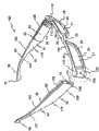
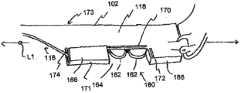
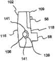
图1是照明眼镜的透视图,显示边撑臂元件相对于横撑架元件处于枢转打开的构造,同时每个边撑臂或前架上的LED光源靠近横撑架元件的相应端部布置; Figure 1 is a perspective view of illuminated eyewear showing the temple arm members in a pivoted open configuration relative to the cross-bracing member, with LED light sources on each temple arm or front frame positioned adjacent to the respective end of the cross-bracing member ;
图2是边撑臂元件之一的平面图,表示电池盒盖和照明开关致动器; Figure 2 is a plan view of one of the temple arm elements showing the battery compartment cover and light switch actuator;
图3是图2所示的边撑臂元件的一部分的放大分解图,显示沿边撑臂元件的内表面形成的电池盒; Figure 3 is an enlarged exploded view of a portion of the temple member shown in Figure 2 showing a battery compartment formed along the inner surface of the temple member;
图4是另一边撑臂元件的放大图,显示靠近电池盒的开关盒; Figure 4 is an enlarged view of the brace element on the other side, showing the switch box next to the battery box;
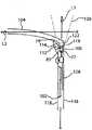
图5是放大的局部平面图,显示LED相对于其上射出光锥的眼镜架元件的定位; Figure 5 is an enlarged fragmentary plan view showing the positioning of the LED relative to the spectacle frame element from which the light cone emerges;
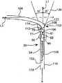
图6是放大的局部平面图,显示LED相对于其上射出光锥的眼镜架元件的不同位置; Figure 6 is an enlarged partial plan view showing different positions of the LEDs relative to the spectacle frame elements on which the light cone emerges;
图7是横撑架元件的放大透视图,显示在其端部形成的贯穿特征; Figure 7 is an enlarged perspective view of a cross brace element showing through features formed at its ends;
图7A是横撑架元件和边撑臂元件处于使用构造的顶剖视图,在该构造下光源安装在边撑臂元件上并且横撑架元件的贯穿部分具有同轴的倾斜轴线; Figure 7A is a top cross-sectional view of the cross brace element and temple arm element in a use configuration in which the light source is mounted on the temple arm element and the through portion of the cross brace element has coaxial tilt axes;
图8A是横撑架元件的放大透视图,显示在其端部的不同贯穿特征和相关插入件; Figure 8A is an enlarged perspective view of a cross brace element showing various through-features and associated inserts at its ends;
图8B是放大局部剖视图,显示图8A所示的横撑架元件和插入件; Figure 8B is an enlarged partial cross-sectional view showing the cross brace elements and inserts shown in Figure 8A;
图9A是横撑架元件放大透视图,显示其端部的另一贯穿特征和相关插入件; Figure 9A is an enlarged perspective view of a cross brace element showing another through-feature and associated insert at its end;
图9B是放大局部剖视图,显示图9A所示的横撑架元件和插入件; Figure 9B is an enlarged partial cross-sectional view showing the cross brace elements and inserts shown in Figure 9A;
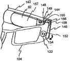
图10是照明眼镜的局部透视图,显示处于部分枢转位置的边撑臂元件和靠近该边撑臂元件的前内端定位的开关; Figure 10 is a partial perspective view of illuminated glasses showing the temple arm member in a partially pivoted position and a switch positioned near the front inner end of the temple arm member;
图11是图15所示的边撑臂元件的透视图,显示靠近该边撑臂元件的前内端定位的开关; Figure 11 is a perspective view of the temple arm member shown in Figure 15, showing a switch positioned near the front inner end of the temple arm member;
图12是照明眼镜的局部透视图,显示边撑臂元件包括具有可移动门的电源盒; Figure 12 is a partial perspective view of illuminated glasses showing temple arm elements including a power box with a movable door;
图13是照明眼镜的局部透视图,显示边撑臂元件包括具有多级电平设定的可选择的开关; Figure 13 is a partial perspective view of illuminated glasses showing temple arm elements including selectable switches with multi-level level settings;
图14是照明眼镜的局部透视图,显示边撑臂元件具有安装在其上以对向眼镜的电源提供的电平进行控制的旋转变光开关; Figure 14 is a partial perspective view of illuminated eyewear showing the temple member with a rotary dimmer switch mounted thereon to control the level of power supplied to the eyewear;
图15是照明眼镜的前平面图,显示嵌入横撑架元件内的发光体; Figure 15 is a front plan view of the illuminated glasses showing the light emitters embedded in the cross brace elements;
图16是照明眼镜的放大横截面图,显示横撑架元件具有多个结构层和在其中的空腔,光源容纳在所述空腔内; Figure 16 is an enlarged cross-sectional view of illuminated glasses showing a cross-bracing member having a plurality of structural layers and a cavity therein within which a light source is housed;
图17是照明眼镜的局部透视图,显示在边撑臂元件与横撑架元件之间的电连接件; Figure 17 is a partial perspective view of illuminated glasses showing electrical connections between temple arm elements and cross brace elements;
图18是照明眼镜的局部透视图,显示边撑臂元件与横撑架元件之间的电连接件; Figure 18 is a partial perspective view of illuminated glasses showing electrical connections between temple arm elements and cross brace elements;
图19是用于照明眼镜的LED的放大透视图,显示LED镜片上的磨砂层; Figure 19 is an enlarged perspective view of an LED used to light glasses, showing a frosted layer on the LED lens;
图20是照明眼镜的局部顶平面图,显示横撑架元件和从其上向后延伸并具有凹入外表面的电源盒的边撑臂; Figure 20 is a partial top plan view of the illuminated glasses, showing the cross brace element and the temple arm of the power box extending rearwardly therefrom and having a concave outer surface;
图21是照明眼镜部分剖视的放大局部平面图,显示横撑架元件具有贯穿部分并且横撑臂元件枢转连接在横撑架元件上,所述横撑架元件具有安装成突出超过其前端的光源; 21 is an enlarged fragmentary plan view of the illuminated glasses, partly in section, showing a cross brace member having a through portion and pivotally connected to the cross brace member having a cross brace member mounted so as to protrude beyond its front end. light source;
图22是边撑臂元件的放大分解图,显示在边撑臂元件中的电源盒和枢转安装在边撑臂元件上的电源盒盖;以及 Figure 22 is an enlarged exploded view of the temple arm member showing the power supply box in the temple arm member and the power supply box cover pivotally mounted on the temple arm member; and
图23是边撑臂元件的放大顶平面图,显示安装在其前表面上的光源和绕光源部分延伸的阻光延伸部。 23 is an enlarged top plan view of a temple arm member showing a light source mounted on its front surface and a light blocking extension extending partially around the light source. the
具体实施方式Detailed ways
总体来说并如下文进一步所述,提供可以包括或不包括连接在其上的镜片或多个镜片的照明眼镜,其被设置成使光向佩戴者前方射出。总体如图1所示,照明眼镜100可以被构造成具有常规眼镜框架或框架组件,其具有多个大体上刚性的框架元件,包括一对间隔的边撑臂部分或元件102,其具有在边撑臂元件102 之间横向延伸的横撑架部分或元件104形式的前支承件。如图所示,边撑臂元件102在横撑架元件104的横向相对端部或外部110与边撑臂元件102的前端部108之间的接合处经由铰链112与横撑架元件104枢转相连。边撑臂元件102备选地可以与横撑架元件104一体或通过其他方式固定连接在其上。 In general and as further described below, illuminated eyewear, which may or may not include a lens or lenses attached thereto, is provided that is configured to project light forwardly of the wearer. As generally shown in FIG. 1 , illuminated
还可以想到发光眼镜的横撑架104的其他构造,包括横撑架元件104变型为包括几个部件或部分,或者备选地这些部件基本上被省去,使得横撑架仅包括在其任意端部与镜片21相连的中间桥部或元件20。镜片21还可以具有仅与其横向外部相连的外前框架部分,使得横撑架元件包括多个部分。备选地,仅设置单个镜片21,其在边撑臂元件102的向前端部108之间延伸并与它们枢转相连,同时桥部20与镜片21一体结合。镜片21本身可以具有折射率以提供视觉修正或没有折射率从而仅提供透明防护罩,如同安全眼镜一样。显然,当眼镜框架仅被用于提供免提发光装置时无需设置镜片或多个镜片21。在此,术语“前支承件”考虑到了用于具有或不具有镜片的单个或多个部分的所有这些和其他构造。 Other configurations for the
照明眼镜100还包括安装在其上以在佩戴者前方提供照明的一个或多个光源106。光源106可以安装在横撑臂102和/或前横撑架104上。光源106优选是发光二极管(LED),但也可以采用其他适当的场致发光灯、适当的白炽灯、气体放电灯、高强度放电灯或任何其他适当的光源,例如激光器二极管。在所示形式中,LED包括具有圆柱形底部77和拱形顶部79的镜片75。镜片75内的二极管或照明芯片81利用电能供给通电并在LED前方射光。 The illuminated
在另一方面,照明眼镜的光源106以一定角度向内和/或向下倾斜,所述角度使光源的光锥可以在佩戴者前方的可视或阅读区域内相交或照亮。在佩戴照明眼镜100时通过自动将光引向该可视区域而无需调节光,照明眼镜100的佩戴者几乎不需要转动、倾斜或通过其他方式控制他/她的头的定位就可以使光落入可视区域内。可视区域与佩戴者前方的区域相一致,例如对手持物体或由佩戴者所工作的物体(例如工具、书、工作台等)进行照明的作业区域。 In another aspect, the
参照图1-7,更详细地示出了示例性照明眼镜100的一种形式。如上所述,前支承件或横撑架元件104包括在端部110中间的桥部20。桥部20被构造成使横撑架元件104可以压在佩戴者鼻梁上并由其支承。桥部20包括向下和向后延伸的侧架22,其被构造成与佩戴者鼻子的侧面接合。如图所示,桥部20是整体式结构,具有大体上截头三角形形状,然而桥部20备选地可以包括其他构造,例如采用连接在横撑架元件104上的可调节垫,其被构造成代替侧架22和框架构造接触并压在佩戴者鼻子的侧面。 Referring to Figures 1-7, one form of exemplary
在所示形式中,照明眼镜100的横撑架元件104包括从桥部20的两侧向其端部110延伸的上框架元件24和下框架元件26。然而,前支承件104也可以包括仅具有上框架24或下框架26的部分框架构造。在无框架方案中,前支承件104包括直接连接在镜片上的桥部20,其随后直接连接在边撑臂元件102上或可以具有使镜片与边撑臂元件102连接的中间部分。也可以采用用于前支承件的其他构造,如之前所述。 In the form shown, the
端部110向后延伸并与边撑臂元件102枢转相连。如图所示,上框架元件24和下框架元件26构成封装镜片21的镜片区域28。镜片开口28被构造成支承多种类型的眼镜镜片。例如,镜片区域28可以被用于支承安全眼镜、太阳镜、处方镜片、其他防护眼镜或它们的任何适当组合所用的镜片。备选地,镜片区域28可以空置和/或横撑架元件104可以被形成为不具有上框架元件24或下框架元件26,如上所述。
通过一种方案,边撑臂元件102通过铰链112与前支承件104的端部110相连以使边撑臂元件102相对于其枢转。然而,如上所述,边撑臂元件102还可以与前支承件104一体或刚性连接在其上。图1表示打开或使用构造,在这一构造下,边撑臂元件102从前支承件102向后延伸,并优选沿着纵向轴线L1大体上垂直于横撑架元件104,纵向轴线L1大体上与横向轴线L2正交,横撑架元件104大体上沿横向轴线L2延伸。然而将会认识到,边撑臂元件102和前支承件102可以各自具有更紧密符合佩戴者头部的曲率。另外,边撑臂元件可以与前支承件成一定角度并有弹性。如此构造,眼镜的佩戴者可以拉开边撑臂元件并把眼镜放在他/她的头上,边撑臂元件随后弹性夹持佩戴者头部以实现更紧固的佩戴构造。 By one approach, the
边撑臂元件102还可以被构造成枢转或平移到折叠、闭合或存放构造,在该构造下每个边撑臂102大体上靠近横撑架元件104沿L2轴线横向延伸。在另一形式中,照明眼镜100的框架可以被制成是在边撑臂元件102与横撑架104之间缺少枢转或铰链连接件的单一、整体部件。在该形式中,边撑臂元件或部分102沿纵向轴线L1永久从横撑架元件或部分104向后延伸。在此针对边撑臂元件102和/或横撑架元件104所述的发光部件结合在该整体框架的相应结构内。 The
如上所述,边撑臂元件102在横撑架元件104的端部110与边撑臂元件102的前端部108之间的接合处经由铰链112与横撑架元件104枢转相连。在所示的形式中,每个边撑臂元件102包括靠近边撑臂元件102的前端108的扩大部分32。边撑臂元件102从扩大部分32到中间部分34向后过渡,具有被构造成压在佩戴者耳朵上并由其支承的狭窄部分35。边撑臂元件102终止在向内且向下指向的远 端部分36处,该远端部分36从中间部分34向后定位并靠近边撑臂元件102的后端37。如此构造,边撑臂元件102从靠近眼睛到耳朵后面的位置大体上符合佩戴者头部的轮廓。如图所示,扩大部分32、中间部分34和远端部分36具有大体上平直的构造。当然,也可以采用其他构造。 As mentioned above, the
现在参照图2-4,光源106需要电子系统50供电。如上所述,为了保持照明眼睛100对外的视觉美观,电子系统50位于每个边撑臂元件102的内表面部分118上并穿过该内表面部分118可以接触到。使电子系统50定位在内表面部分118上可以在佩戴照明眼镜100时有效地将电子系统50隐藏为不可见。内表面部分118可以具有基本上平直的构造并且可以定位成使得在边撑臂元件102移动到打开构造时每个边撑臂元件102的内表面部分118相互面对。在所示形式中,内表面部分118包括下部51和略微突出的部分53。略微突出的部分53优选靠近前框架104,但也可以定位在边撑臂元件102的中间部分34或远端部分36上。更具体地,电子系统50可以布置在边撑臂元件102的扩大部分32的内表面部分118和外表面部分116之间。如此构造,在边撑臂元件102的外表面部分116上看不到电子系统50的任何部件。 Referring now to FIGS. 2-4 , the
在一种方案中,边撑臂元件102(优选是两个边撑臂元件102)的内表面118包括在凹入其中的电源盒54,其可以封装电子系统50。电子系统50可以包括开关56、电源66及其电子连接件。如图所示,开关56是滑动开关,然而,可以采用其他类型的开关,例如触发器、按钮或接触开关。如图4所示,开关56与光源触点57中的一个以及还与电源66相连。 In one aspect, the
优选地,开关56靠近铰链112安装在边撑内表面部分118上。开关盖109通过任意适当的机构(包括粘合剂、紧固件或类似物)安装在边撑臂元件102上以封盖开关电子部件61并将开关电子部件61保持在盒54中。优选地,开关盖109的向内面对表面基本上与边撑臂内表面188的突出部分53平齐,使得突出部分53具有基本上平的构造。开关盖109其上包括开口69,用于开关56的致动器部分59从中突出以由眼镜100的佩戴者接触。开口可以被构造成可以操作用于任意适当的开关,包括例如用于滑动开关的细长开口、用于旋转开关的圆开口等。特别地,铰链112利用销或螺钉紧固件61使前边撑部分58与外或边缘横撑架部分60枢转相连。为了保留空间并最大限度地减小电子系统50的长度,开关56可以与铰链112的边撑部分58布置成垂直关系。在图2-4所示形式中,开关56靠近边撑臂元件102的前端面114以及靠近边撑臂元件102的上表面62定位在铰链112的上方。相应地,铰链112的边撑部分58靠近边撑臂元件102的下表面 64。如此构造,开关56定位成由佩戴者的食指操纵以控制向光源106的供电。备选地,开关56可以靠近边撑臂元件102的下表面64定位并且铰链112的边撑部分58可以定位在开关56的上方并靠近边撑臂元件102的上表面62。 Preferably, switch 56 is mounted on temple
图6表示开关88控制光源106的电力的备选位置。如图所示,开关88安装在边撑臂元件102的外表面116上,例如安装在边撑臂元件102的前端部分114上或附近。这样使开关88有利地定位成靠近电源盒54和光源106。开关88可以是按钮开关、滑动开关、旋转开关等。优选地,开关88包括例如由塑性材料、金属材料或其组合物构成的保护盖90。在一种形式中,保护盖90可操作地与开关88相连以作为致动器或与致动器相连,使得保护盖90可以得到操控以对开关88进行操作。这一点可以通过保护盖90来实现,其对于滑动开关来说保护盖90与边撑臂元件102的外表面116处于滑动关系,对于按钮开关来说保护盖90具有可压下或柔性区域,或者对于旋转开关来说保护盖90与边撑臂元件102的外表面116处于旋转关系。保护盖90还可以保护开关88的部件不会因常规磨损和撕扯或照明眼镜100跌落而受损。有利地,保护盖90还可以被构造成部分或完全隐藏开关88,使得照明眼镜100保持传统眼镜的外观或美观。 FIG. 6 shows an alternate position for
在一种形式中,保护盖90还可以被用于展示字母数字或图形内容,例如公司标志、广告语、商标等。当照明眼镜处于打开或使用构造下时,保护盖90在边撑臂元件102的外表面116上的定位向外明显展示所述内容,这样可以提供广告或增强品牌识别。在另一形式中,保护盖90可以定位在边撑臂元件102的外表面116上,例如处于大体上与开关56相对的位置,以对开关56和/或电子组件50的其他部件提供外部保护。 In one form,
通过一种方案,电源盒54相对于边撑臂102的厚度具有较窄宽度并定位在内表面部分118与外表面部分116之间。这种宽度较窄的盒54使边撑臂元件102能够保持相对较薄的形状,从而可以在佩戴者头部上提供比更厚的边撑臂元件更舒适的佩戴。电源盒54还靠近铰链112的边撑部分58定位并且可以部分地凹入边撑臂元件102内。在所示的形式中,盒54包括向外延伸边缘65,其分隔在边撑臂内表面部分118的下平直部分51的上方的突出部分53。盒54的深度被构成封装向光源106供电的一对处于纵向非重叠、并排关系的电池66,例如一对盘形纽扣电池,使得电池66的主表面面向边撑臂元件102的内表面部分118和外表面部分116。通过另一方案,盒54可以被构造成在其中容纳充电电池,例如具有大体上矩形构造的电池。盒54还可以包括部分容纳开关56的凹部67,例如开关56与电池66和光源106电连接的电触点和/或连接线。如此构造,当佩戴照明眼 镜100时,电源盒54基本上隐藏了电池或多个电池66和开关56为不可见。 By one approach, the
备选地,边撑臂元件的扩大部分108可以相对于边撑臂元件102的中间和后部34,36在至少相互正交且与边撑臂元件102的纵向轴线L1正交的两个方向上延伸,例如在大体上横断内和外表面部分118,116的横向上和在大体上横断上和下表面部分121,123的垂直方向上。在该备选结构中,盒54可以比边撑臂从其向后延伸的其余部分更厚且更高,并因此在其中支承处于堆叠或重叠关系的一对电池66或更厚的充电电池。同样,可以仅采用一个电池66。 Alternatively, the
当电池66处于图3和4所示的纵向并排关系时,盒54被分成两个间格68,每个间格68优选具有至少部分地绕其延伸并被构造成支承和横向封闭单个电池66的边缘65。远间格68包括在其下表面上被构造成支承触点72(例如与开关56相连的叶片连接器)的凹部70。通过将垂直触点壁部74插入在边缘65上形成的凹槽或多个凹槽中,触点72可以例如通过摩擦配合固定在适当位置。触点72与如上所述连接在光源106上的触点57上的开关56电连接。特别地,导线76通过固定在其他间格68上方或下方(优选根据开关56的定位而确定)的盒54内的空间内而从触点72延伸到开关56。导线76可以沿其长度的至少一部分由绝缘材料或护套至少部分地封盖。如图所示,触点72被构造成接触电池66的阴极。另一间格68可以靠近开关56定位并包括在其下表面79上的凹部78,其被构造成支承光源106的第二触点80。如图所示,触点80是出自光源106的细长导线之一并容纳在细长凹部78内以被构造成接触另一电池66的阳极。如此构造,一个电池66的阴极与开关56相连,开关56与光源106相连,并且另一电池66的阳极直接与光源106相连。这种构造使开关56可以控制向光源106的供电以使其打开和关闭。尽管示出了触点72、80和电池66的一种特别的构造,但如果需要这些部件也可以相反。 When the
通过一种方案,内表面部分118的突出部分53包括活动盖82,如图2和3所示,其被构造成固定装配在盒54上以使电池66固定在其中。盖82可选择地包括在其内表面上向电池66施加向外压力使得电池66紧固在触点72,80上的偏压元件(例如弹簧)。盖82通过舌槽机构固定在盒54上,所述机构包括与设置在边壁65上或内的边缘或切口相配合的盖82的依托侧面和远端的部分或突出部。也可以采用其他适当的固定机构。在所示的形式中,盖82由金属(与眼镜及其边撑部分的优选塑料相反)制成以限制边撑臂元件12的厚度。塑料盖厚度增大,这样会影响边撑壁元件102的薄构造,但是如果足够薄和坚固也可以被采用。 By one approach, the protruding
在图22中示出了备选的盖83与边撑壁元件102组合。在图22中示出的边撑壁元件102与以上针对盒54所述的边撑壁元件102基本上类似,除了以下所述的区别。如图所示,盖83包括在其下部从盖83的后端89向后突出的突起或突出部87。突起87包括圆周边缘,但可以按照需要具有其他形状。连接开口91延伸穿过突起87,使得盖83可以连接在边撑壁元件102上。边撑壁元件102包括相应安装突起或突出部93,其上具有被构造成在利用适当的连接装置(例如螺钉紧固件97、销等)将盖83安装在边撑壁元件102上时与盖突起87上的开口91对准的螺纹开口或孔95。开口91尺寸大于螺钉紧固件97,使得螺钉紧固件97从中穿过,但仅螺纹连接在螺纹孔95内。如此构造,盖83可以枢转连接在边撑壁元件102上,因此可以在封盖电源盒54的间格68并将电池66固定在其中的闭合位置与充分露出间格68以使电池66可以被取出和更换的打开位置之间枢转。 An alternative cover 83 in combination with a
为了将盖83固定或保持在闭合位置,盖83包括从盖83的前端弯曲并延伸以与其偏离的薄闭锁元件99,并且边撑壁元件102包括相应凹入切口101,其尺寸被设计成在盖83枢转到闭合位置时在其中容纳盖闭锁元件99。在所示形式中,切口101设置在边撑壁元件102与安装在边撑壁元件102上的开关盖109的后边缘部分之间。 To secure or maintain the lid 83 in the closed position, the lid 83 includes a
为了减小边撑壁元件102的厚度,盖83优选具有薄的、基本上平的构造,一种方案是通过采用坚固材料(例如金属)构造盖83来实现。盖83还可以包括向边撑壁元件102向内突出以沿顶部且部分沿盒54的侧面到下盖突起87附近的位置与盒边壁65重叠的薄唇部103。有利地,唇部103还作为盖83完全旋转到闭合位置时的止动表面,因为当盖83完全枢转以封盖盒54时盖83的唇部103抵靠和压在边壁65的上表面上。如图所示,盖83还可以包括安装在其内表面111上的触点105,从而形成电池盒54面向电池66的具有触点105内表面,该触点105具有两个向内突出臂107。当盖83处于闭合位置时,触点臂107定位成与间格68中的电池66的露出主表面接触并由此电连接。优选地,触点臂107受偏压向内突出以确保与电池主表面稳固接触并且还因与电池主表面的抵靠而向外推压盖83。向外的力促使闭锁元件99沿切口101紧密摩擦接合开关盖部分109以抵制盖83枢转到打开位置。 In order to reduce the thickness of the
在图20中示出了备选的电源盒84。这一形式的备选电源盒84布置在边撑臂元件102的内和外表面118,116之间,在外表面116上具有开口85,使得在佩戴眼镜100时或在边撑臂元件102枢转到存放构造时,盒54凹入外表面116内, 从而可以很容易接触到电池。备选的电源盒84包括与上述电源盒54类似的结构,例如封装电源66(如在纵向并排定向上的一对电池或充电电池)的结构,以及从电池向光源106供电所需的部件,例如导线、触点等。电子系统50的其他部件(例如开关56)可以如上所述安装在内表面118上,或者备选地可以安装在外表面116上,在靠近备选电源盒84的位置。备选电源盒84优选包括活动盖86。活动盖86可以与上述盖82或83结构类似,例如通过舌槽结构固定在边撑臂元件102上。 An alternative
盖86备选地可以包括沿盒54边缘之一的可枢转或可旋转结构,例如铰链等,使得盖86可以绕铰链枢转以选择性露出和闭合盒54。例如,铰链可以沿盒的上或下边缘纵向布置并且盖86可以绕铰链相应向上或向下枢转。在另一实例中,铰链可以大体上与边撑臂轴线L2正交地布置在盒的前向或后向边缘上并且盖86可以绕铰链相应向前或向后枢转。盖86还可以包括偏压元件,例如弹簧,使得盖86被偏压到闭合位置。
在图1所示的形式中,每个边撑臂元件102在其扩大前部108处封装至少一个光源106。备选地,照明眼镜100可以采用一个或多于两个的光源106。如上所述的光源106优选是LED。在下文更详细论述的一方面,光源106可以以一定角度向内和/或向下倾斜,所述角度使光源106的光锥可以相交在佩戴者前方可视或阅读区域内。在佩戴照明眼镜100时通过自动将光引向该可视区域而无需调节光,照明眼镜100的佩戴者几乎不需要转动、倾斜或通过其他方式控制他/她的头的定位就可以使光落入可视区域内。 In the form shown in FIG. 1 , each
在所示形式中,照明眼镜100的横撑架元件104在中间桥部20的任意一侧包括端部或外部110。然而如之前所述,还可以采用用于前支承件104的其他构造。端部110通过铰链112与边撑臂元件102枢转相连。当枢转到图1所示的打开或使用构造时,边撑臂元件102沿大体上与横向轴线L2正交的纵向轴线L1从横撑架元件前支承件104向后并优选大体上垂直于横撑架元件104延伸,横撑架元件104大体上沿横向轴线L2延伸(例如参见图5)。边撑臂元件102还被构造成枢转或移动到折叠、闭合或存放构造,此时每个边撑臂元件102沿靠近横撑架元件104的轴线L2横向延伸。 In the form shown, the
光源106可以相对于边撑臂轴线L1和横撑架轴线L2倾斜,使得光源106将光引向照明眼镜100前方的所需可视区域,而无需佩戴者倾斜或移动他们的头部。例如,光源106可以相对于边撑臂轴线L1向下倾斜以在眼镜100的前方和下方的区域进行照明,并且可以相对于边撑臂轴线L1向内倾斜,使得光源106的光 锥在正常聚焦之前聚焦在大体上共用的可视区域内(也就是靠近佩戴者,例如如果光锥轴线与相应边撑臂轴线L1同轴则成大致10英寸到大致18英寸的阅读距离)。在美国申请12/895,456中描述了涉及照明眼镜倾斜光源的其他公开内容,该申请结合在此。通过另一方案,光源106可以以不同角度倾斜以对两个或多个不同的可视区域进行照明。例如,一个光源可以相对于边撑臂轴线L1向内和向下倾斜以照明可视区域,另一光源106可以不倾斜或包括相对于边撑臂轴线L1很小的向内倾斜以对眼镜前方和相对于其更远距离的区域进行照明。
如图所示,每个边撑臂元件102包括靠近每个边撑臂元件102的前端表面或部分114的扩大部分108,扩大部分108向后的结构可以如上文针对眼镜10所述那样被构造。在该实施方式中,边撑臂元件102包括外表面部分116和内表面部分118。外和内表面部分116,118如图所示具有大体上平直的构造。优选地,如图1所示,外表面部分116的平直构造完全不破裂,保持传统眼镜的外观。然而备选地,外表面部分116其上可以具有突出部,例如至少部分地封盖光源106的元件或其他机械、电动或美观的特征。 As shown, each
在该形式中,光源106优选至少部分地安装在边撑臂元件102的扩大部分108上凹入在其前表面114内。通过一种方案,每个光源106安装在外和内表面部分116,118之间,例如以不干扰外和内表面部分116,118平直构造的方式得到安装。如图5和6所示,光源106与镜片区域21相关地凹入,使得光源106沿边撑臂轴线L1相对于镜片区域21向后安装。利用这一构造,当佩戴照明眼镜100时,光源106位于横向靠近佩戴者的眼睛而不是像镜片区域21一样位于佩戴者眼睛的前方。基于这一点,边撑臂元件102的内表面部分118优选在靠近光源106处是不透明或阻光的,从而基本上防止不想要的杂散光或眩光穿过边撑臂元件102的内表面部分并进入佩戴者的眼内和/或照明眼镜100的镜片28内。备选地,光源106可以如上所述至少部分地安装在从每个边撑臂元件102的外表面部分116略微向外延伸的突出部或管状元件内。如图所示,每个光源106在边撑臂元件102内大体上居中垂直安装,其中其大体位于在外和内边撑侧表面116和118之间的上和下表面121,123中间,然而,光源106可以按照要求或需要安装在所示位置上方或下方。 In this form, the
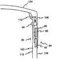
在一种形式中,如图5所示,光源106的前镜片部分119延伸超过边撑臂元件102的前端表面114。在略微不同的形式中,光源106可以完全容纳在边撑臂元件102内,如图6所示。在任一构造下,光源106被封装成至少部分地固定在边撑臂元件102上以与其一起枢转。当边撑臂元件102枢转到使用构造时,光源 106定向成将光投射到大体上照明眼镜100前方的位置。当处于使用构造时,横撑架元件104的端部110至少部分地位于光源106的光锥内(可以在图5和6中看到),并被构造成使得照明光穿过横撑架元件104尤其是穿过横撑架端部100的贯穿部分122投射。在这些形式中,贯穿部分122是开口或孔(图5),或由例如丙烯酸酯、聚碳酸酯等材料制成,使得光源106可以将光穿过横撑架元件104(图6)投射到照明眼镜100前方,同时也使光源106至少部分地隐藏为不经意观察不可见。在一种方案中,贯穿部分122不折射,使得由光源106发出的光的投射路径在光穿过贯穿部分122以照亮照明眼镜100前方的同时基本上恒定。 In one form, as shown in FIG. 5 , the
在图6所示的形式中,光源106容纳在如上所述的边撑臂元件102内。为此,贯穿部分122还可以包括端部108,其包含边撑臂元件102的前端表面114。因此,为了使从光源106投射的光从边撑臂元件102内发出,边撑臂元件102位于光源106前方的前端108可以是透明或半透明的,可以包括开向前端表面114的孔或其他开口等。如此构造,光源106可以完全容纳并隐藏在边撑臂元件102内以从边撑臂元件102的前端表面114向回凹入,同时仍然使光穿过贯穿部分122从边撑臂元件102向前投射出去,这一点在下文将更详细地论述。 In the form shown in Figure 6, the
如图1,5,6和21构造的照明眼镜100在边撑臂元件102处于打开、使用构造时将横撑架元件104,特别是其端部110定向在安装于边撑臂元件102上的光源106的前向或前方,使得端部110在未破裂和不透明的情况下基本上阻隔光源106的光锥120。因此,每个端部110的横撑架元件104的贯穿部分122可以使至少一部分光锥120在照明眼镜100的前方穿过横撑架元件104照亮。 1, 5, 6 and 21, the illuminated
在图7-9B中示出了示例性贯穿部分122。通过对一些或所有横撑架元件104采用透明或半透明材料部分来提供第一形式的贯穿部分122。这样使光源106可以穿过横撑架部分104与LED光源106的光锥相交的部分亮光。备选地,在图7所示的第二形式中,在横撑架元件104的端部110包含光接收器部分124。可以通过任何适当的方式形成接收器部分124,例如钻孔从横撑架元件104上去除材料以在端部110上形成空腔125,将横撑架元件104模制成包括空腔125,等等。如图所示,接收器部分124是孔、通道或管形式的。在最简单的形式中,保留接收器部分124不具有其他特征,从而提供使光源106发出的光在照明眼镜100的前方照亮的通道。这样,空腔125在横撑架元件104的后表面129包括后孔127。在边撑臂元件相对于横撑架元件枢转的形式中,后孔127和至少空腔125的后部相对于光源LED106(特别是圆柱形和拱形盖部77,79)的直径具有更大尺寸,使得在边撑臂元件102枢转到使用位置时,光源LED 106可以部分枢转到空腔 125内,而不接靠或接触横撑架元件104。 Exemplary through
在此所述的所有贯穿部分122还可以定位成适应上述光源的倾斜。具体地,贯穿部分通过也以与上述光源类似的方式倾斜来适应光源106的倾斜。例如,贯穿部分122可以相对于边撑臂轴线L1向内倾斜和/或相对于边撑臂轴线L1和横撑架轴线L2向下倾斜,当边撑臂元件102枢转到打开或使用构造时,所述横撑架轴线L2大体上横断边撑臂轴线L1。贯穿部分122的倾斜可以被用于大体上与光源106的倾斜相一致,使得贯穿部分122可以与相应的光源106轴向居中。换句话说,分别的,LED光源106和相应的贯穿部分122的中心轴线C1可以相同。而且,贯穿部分122可以具有比光源投射的光锥更大或更小的形状,或者在其上包括涂层或层以使从光源106投射的光锥聚焦或构成到上述可视区域。 All through
可选择地,绕接收器部分124延伸的内表面134在其至少一部分上可以包括材料或涂层以使来自光源106的光输出最佳并使浪费的光最少。材料或涂层可以是任何适当的反射材料或具有适当反射率的表面,例如银涂层、镍涂层、锂银镀层、镍锂镀层,等等。在另一形式中,如果横撑架元件104由至少部分光透射材料构成,则绕接收器部分124延伸的内表面134可以备选地或除此之外包括阻光层或涂层,其被构造成减少从光源106穿过横撑架元件104投射到佩戴者眼内或在镜片28上引起强眩的不想要的杂散光的量。 Optionally,
备选地,接收器部分124可以包括光管、光纤或其他光透射材料140,其安装在接收器部分124上可操作将光引导穿过横撑架元件104或使光从中穿过。这些特征使光源106发出的光穿过横撑架元件104,同时也降低了光损失。 Alternatively,
如图8A和8B所示,在第三形式中,接收器部分124包括向后延伸的截头圆锥形切出部分126,其中底部切出锥形部分基本上与向前定位、大体上圆柱形的切出部分128轴向对准。截头圆锥形部分126延伸并在横撑架元件104的后表面部分129开口以形成后孔131,其在边撑臂元件102处于打开或使用构造时定向成与至少部分地安装在边撑臂元件102内的光源106大体上对准或同轴重叠。前圆柱形部分128优选沿光源106的轴线C1大体上居中并在横撑架元件104的前表面135上开口以在其上形成前孔或开口133。优选地,后孔131的直径尺寸为与光源106的镜片75的直径基本上匹配或比其略大。这一构造最大程度的减少浪费的光,因为大部分从光源106投射的光在光接收器部分124内得到接收。另外,尤其在图5所示的形式中,后孔131可以部分接收从中穿过的光源106。例如,光源镜片75的直径可以为大约3mm,截头圆锥形部分126的孔131的直径可以为大约3mm或更大。而且,截头圆锥形部分126可以形成在截头圆锥形部 分126与圆柱形切出部分128相交处达到5mm或更大直径的锥度。而且,圆柱形部分128可以基本上保持这一直径直至横撑架元件104的前表面135。对于切出部分126已经论述了锥和圆柱结合,但可以采用其他适当的构造,例如锥、圆柱、金字塔、棱形、长方体、球体、扁长椭球形、一种或多种形状的组合、不同尺寸形状的组合、这些形状的一部分,等等。 As shown in FIGS. 8A and 8B , in a third form, the
除此之外,横撑架元件104可选择地包括插入件136,其被构造成匹配和装配在接收器部分124内,使得横撑架元件104的前表面135基本上未出现破裂(参见图8B,9A和9B)。插入件136可以与接收器部分124具有基本上相同的形状和尺寸,或者可以被构造成装配在更小部分内,例如接收器部分124的前或后区域。优选地,插入件136尺寸被构造成使得当装配在接收器部分124中时,其前表面151与横撑架前表面135平齐。插入件136可以通过任何适当的机构固定在接收器部分124内,例如粘合剂、压配合、螺纹、紧固件、热密封,等等。在该形式中,插入件136被构造成使得来自光源106的光穿过插入件136投射在照明眼镜100的前方。这样,插入件136可以由任何适当的半透明或透明材料制成,使得至少来自光源106的一些光被滤过或穿过插入件136被投射。同时,插入件136可以由与横撑架元件的材料协调的材料构成以保持眼镜框架的总体外观。插入件136还可以具有折射以按照要求聚焦或分散LED发出的光锥、扩散以使光柔和、和/或可以得到着色以在眼镜100的前方投射彩色光。 In addition, the
在图21所示的另一形式中,贯穿部分122被形成为具有大体上圆柱形构造并延伸穿过横撑架部分104以在其后表面129和前表面135上开口的通孔。贯穿部分122定向成使得当边撑臂元件102处于使用位置时,LED光源106的镜片75的前部至少部分地延伸到贯穿部分122内,LED光源106向前投射超过边撑臂元件102的前端表面114。如图所示,这包括镜片75的圆柱形底部77的前部和拱形盖部79。如上文所述,至少贯穿部分122的后部相对于LED 106(特别是其圆柱形底部77)的直径具有更大尺寸,使得在边撑臂元件102枢转到使用位置时,LED 106可以部分枢转到贯穿部分122内以避免与横撑架元件104发生干涉。 In another form shown in FIG. 21 , the through
通过一种方案,边撑臂元件102可以包括远离前端表面114向前延伸以在LED 106的前投射镜片75的旁侧延伸的阻光延伸部139。更具体地,阻光延伸部139是壁形式的,其被形成为在光源106的横向向内,使得其至少部分地处于光源106与边撑臂元件102的内表面118之间。优选地,阻光延伸部139远离边撑前端表面114延伸足够距离以在轴向上延伸超过LED 106的二极管81。阻光延伸部的壁139还可以包括绕镜片底部77延伸的锥形侧壁部分141,使得阻光延伸部 的壁139如图23所示具有弧形构造。在所示形式中,阻光延伸部绕LED 106的镜片底部77至少向内面向的一半包绕。如此构造,当边撑臂元件枢转到使用构造时,延伸部139阻止意外光穿过横撑臂部分104与边撑前端表面114之间的间隙153横向向内投射,以防止意外光照入眼镜100的佩戴者的眼内和/或照入眼镜100的镜片21内。 By one approach, the
在该方案中,贯穿部分的孔122可以包括后部阻光延伸接收部分或凹部143。接收部分143使贯穿部分的孔122,特别是其后部分155的宽度扩大,以适应延伸部139。通过另一方案,半透明或透明盖145可以装配在贯穿部分的孔122的前部159内。优选地,盖145具有与横撑架元件104的前表面135基本上平齐的前表面147。如上所述,盖可以是半透明的、可扩散的、可折射的、和/或具有彩色色彩。 In this aspect, the through-
阻光延伸部139备选地可以从边撑臂元件110向后远离延伸以在安装在边撑臂元件102上的LED 106的前投射镜片75旁侧延伸。在该形式中,延伸部139是壁或突起形式的。延伸部139可以被构造成当边撑臂元件102枢转到使用构造时接靠或紧密靠近边撑臂元件102的前表面114,以阻止意外光穿过横撑架元件104与边撑前端表面114之间的间隙153横向向内投射。在优选形式中,边撑臂元件102可以包括在其前表面114上的袋或凹部,并且当边撑臂元件102枢转到使用构造时,延伸部139可以从横撑架端部110向后延伸以容纳在袋内。壁如上所述可以是弧形的,或者可以大体上与边撑臂轴线L2正交延伸。 The
在图9A-9B中示出了不同形状的示例性接收器部分124和插入件136。在该实例中,接收器部分124具有不同构造的圆柱形部分,包括可以具有圆形横截面构造的向后圆柱形部分137,和可以具有所示大体上椭圆形横截面的向前圆柱形部分138。如上所述,如果需要,相关联的插入件136被构造成装配在接收器部分124内并具有匹配的外形轮廓。
在图10和11中示出了照明眼镜100的另一可选特征,其表示示例性边撑臂元件142。边撑臂元件142基本上与上文针对照明眼镜100所述的边撑臂元件102类似。例如边撑臂元件142被构造成与横撑臂元件104枢转相连。因此,下文将强调不同点。 Another optional feature of the illuminated
边撑臂元件142可以在其前端144包括其他特征。如图10所示,延伸部分146向前伸出超过边撑臂元件142的前肩部表面148并延伸到边撑臂元件102的外表面116。前肩部表面148在延伸部分146的内表面152与边撑臂元件102的内表面118之间横向延伸。前肩部表面148被形成为当边撑臂元件142处于从横 撑臂元件104大体上向后延伸的打开或使用构造时紧密靠近或接靠横撑架元件104的端部110的向后面对表面150。当边撑臂元件142枢转到使用构造并被构造成与横撑架元件104的端部110处于干涉时,延伸部分146与边撑臂一起旋转。特别地,延伸部分146的内表面152定位成紧密靠近或接触横撑架元件104的端部110的侧表面154。该构造可以有利地控制边撑臂元件142的旋转,因为延伸部分146可以提供前肩部表面148之外的限制接触区域,二者在边撑臂元件142完全打开时都具有与横撑架元件104的干涉定位。 The
这一构造还可以有利地被用于提供另一开关156以控制从例如如上所述的其中包含电源的电源盒157提供的电能,以控制光源106的操作。如图10-11所示,开关156包括按钮致动器158并被设置在延伸部分146的内表面152上。如此构造,按钮158被布置并构造成当边撑臂元件142枢转到打开或使用构造时得到按压,横撑架部分104的侧表面154接合延伸内表面152和其上的按钮158。这样有利地提供了无需在边撑臂元件142与横撑架元件104之间具有横跨的电连接件的铰链开关。备选地,开关156可以定位在边撑臂元件142的其他表面上,这些表面旋转以在使用构造时与横撑架元件104接触,例如前表面148。有利地,开关156可以单独使用或与上述开关56组合使用,其中边撑臂元件102的内或外表面118,116上的开关56提供主动力开关并且在主开关打开的情况下,延伸部146上的开关156提供在边撑臂元件102枢转到打开或使用构造时激发光源的瞬时开关。采用两个开关使眼镜100在无需打开光源106的情况下以及在仅具有铰链开关的构造中得到使用,还在眼镜未处于使用构造时防止开关56无意中被转换到打开位置并浪费电池寿命。 This configuration may also advantageously be used to provide a
在图12中示出了边撑臂元件102中的电源盒160的备选构造。图中省去了边撑臂元件102的其他细节以更清楚地示出电池盒160,然而将会认识到,边撑臂元件102可以按照说明书所述那样被构造。如图所示,这种形式的电源盒160包括用于电源162的空间或空腔,例如处于并排结构的两个纽扣电池或充电电池。备选地,电源盒160尺寸可以被设计成以重叠结构支承电池。提供电源盒160入口的开口164至少部分地位于边撑臂元件102的下表面166上。如图所示,开口164可以由活动或滑动平移门或盖168封盖。通过一种方案,门168被构造成可以沿边撑臂元件102的轴线L1纵向移动,例如通过通道或导轨170得到纵向引导,门168在所述通道或导轨中具有至少部分延伸到导向轨道170内的突出部或延伸部,其起到了将门168固定在边撑臂元件102上的作用。在所示形式中,开口164从边撑臂102上切出,其在外和内边撑臂侧面116和118上从边撑臂下表 面延伸。这有利地使得当门168平移到闭合位置时门168的下表面171与边撑臂元件102的下表面166大体上平齐,从而保持照明眼镜100看上去与传统眼镜一样美观。所述开口164包括边撑臂元件102的内和外表面部分116,118的一部分。然而在备选形式中,开口164还可以通过切口的形式单独设置在边撑臂102的下表面166上,其中内和外表面部分116,118基本上未因开口164而破裂。电源盒160还可以被设置成以与针对下表面166所述类似的构造靠近或在边撑臂元件102的上表面173开口。 An alternative configuration of the power supply box 160 in the
另外,边撑臂元件102和门168可以包括棘爪锁定机构172,例如舌槽、搭扣配合等,以将门168固定且可脱开地固定闭合位置,在闭合位置电源162固定在电源盒160内。随后,当需要时,由锁定机构172提供的锁定力可以被克服以使门168沿边撑臂元件102的轴线L3被纵向引导到可接触到电源162的打开位置,如图17所示。边撑臂102可以包括止动特征174,例如通道170的端壁部分,或者包括延伸止动表面174等,以提供防止通过在边撑臂元件102上向后滑动门168而使得门168在纵向上行走太远并放置其与边撑臂元件102分离的接靠表面。然而,如果需要,门168还可以被构造成完全可从边撑臂元件102上拆下,例如通过由至少部分柔性材料制成门,使得门168可以弯曲或旋转脱离导向件170或包括压槽而不是止动件174,使得门168可以通过压槽得到保持或操控以及离开导向件170。 Additionally, the
在图13中示出了照明眼镜100的另一特征。对于照明眼镜100的一些用途来说,需要多种光强度。因此照明眼镜100还可以包括开关180,例如具有多级、不同光强度等级或颜色设定181的滑动开关。这些设定181还可以例如通过具有多个闪烁频率来实现节能。如图所示,多级开关180包括高、中、低和关闭设定181;然而,如果需要还可以设置其他等级。另外,开关180被示出处于靠近边撑臂元件102的上表面182和前端表面184的位置,但开关180可以按照需要位于边撑臂元件12上的任何位置。还可以采用说明书中所述的其他构造。另外,开关180可以是按钮开关。电路板185可以与开关180电连接并被构造成包括根据开关位置使光强度变化的电路。 Another feature of the illuminated
在图14中示出了用于使照明眼镜100的光强度变化的备选机构。在该形式中,调光开关190安装在边撑臂元件102上靠近其下表面191以控制向光源106提供的电量。如图所示,调光开关190包括旋转机构192,其包括以一定方式安装在边撑臂102上的轮,使得其一部分露出以由使用者拇指或食指旋转,从而改变向光源106提供的动力。例如,由照明眼镜100的佩戴者操控转动或旋转所述 轮可以控制光源106的亮度。备选地,可以采用旋转机构192控制光源106闪烁的频率,从而可以提供节能或停帧(freeze frame)/频闪(strobe light)功能。在所示形式中,旋转机构192部分延伸穿过开口194,例如在边撑臂元件102的下表面191上形成的插槽开口。优选地,旋转机构192突出适当距离,例如在超过下表面191从1/16英寸到1/2英寸范围。如此构造,旋转机构192被便利地设置,便于照明眼镜100的佩戴者例如利用拇指或食指接触操控。另外,旋转机构192可以靠近电源盒196(例如上述电池盒54或160)定位,并与其电连接。调光开关190还可以与被构造成根据调光开关位置改变光强度的电路板198电连接。还可以采用提供调光功能的其他适当方法。 An alternative mechanism for varying the light intensity of the illuminated
在图15-18中所示的照明眼镜200包括容纳在横撑架部分204中的一个或多个光源206并且另外包括与上述针对照明眼镜100所述类似的框架结构。例如,照明眼镜200包括与横撑架部分204枢转相连的边撑臂元件202,如上所述。因此,下文将强调区别点。 The illuminated
如图15所示,光源206安装在横撑架部分204上并容纳在其中。图15表示光源206的可行位置,可以包括被安装在横撑架204的端部208上和/或在横撑架204的桥部210上,然而,一个光源206可以提供满意的性能以将光投射到照明眼镜200的佩戴者的前方,因此可以采用上述任何或所有位置。另外,这些位置仅仅是示例性的,还可以采用横撑架部分204上的任何其他位置,例如镜片区域212上方或下方。 As shown in FIG. 15, the
图16表示具有层压结构横撑架元件204的横截面图,其具有封装在其中的光源206之一。优选地,横撑架元件204是至少三层的塑料层压件,然而,可以采用其他适当的层压构造,例如金属或其组合。横撑架元件204包括尺寸被设计成完全封装其中的光源206的空腔、切出部分或开口214。在一种实例中,光源206是表面安装型LED,然而可以采用其他光源。 Figure 16 shows a cross-sectional view of a
在一种形式中,横撑架元件204是基础或内框架元件205夹在外后层216和外前层226之间的三层层压件。通过一种方案,空腔214形成在内基础层205上。外后层216可以包括施加在底部横撑架元件205的后表面218上的薄层压件、涂层、层、油漆、清漆(lacquer)等。后层216大体上构成了其上安装光源206的空腔214的后表面。这一结构使光源206和电连接件220可以位于空腔214内并随后例如通过粘结剂至少向后固定在后层216上。另外,后层216可以是不透明的,以阻止来自光源206的意外光向后照亮在佩戴者眼内或到达佩戴者余光范围内,或者照亮可能干扰和烦扰佩戴者的后层216。电连接件220可以包括与柔性 印刷电路板224电连接的电触点222、一对导线、引线,等等。为此,眼镜200可选择地嵌入所有电气部件以向前框架204上的光源206供电,例如电池、开关和通过导线电连接的其他部件,等等。备选地,一些电气部件可以设置在边撑臂元件202上并且电连接件220可以跨越边撑臂元件202与横撑架元件204之间的连接。 In one form,
照明眼镜100还可以包括封盖空腔214的前开口并作为贯穿部分122的前层。优选地,前层226是透明或半透明层或者包括光源206前方的透明或半透明部分,其可以包括层压件、涂层、层等等,并且可以横跨横撑架元件204的前表面228施加,例如蘸(dipped)、层压或喷漆等等。备选地,前层226可以由可流动且透明或半透明材料构成,例如油漆或清漆。当沉积在空腔214内并在需要的情况下横跨前表面228的至少一部分沉积时,可流动材料可以至少部分地填充空腔214并环绕或封装光源106。在该形式中,可流动材料可以硬化以将光源106固定在空腔214内,和/或作为贯穿部分122。前层226随后可以在光源206完全容纳在横撑架元件204上的空腔214内时保护和/或至少部分地隐藏一个或多个光源206为不可见。为此,光源206安装在空腔中并定向成穿过前层226投射光。前层226还可以被形成为使得横撑架元件204的前表面228基本上未破裂,从而保持了与传统类似的美观。可选择地,前层226可以仅部分地封盖前框架的整个表面,例如仅封盖空腔214。 The
光源206还可以相对于横撑架元件的轴线L2和/或边撑臂元件的轴线L1倾斜,如上所述。据此,光源206可以以所需倾斜角度或多个角度安装在后层216上,或者可以包括被构造成将光源206固定成所需角度的其他安装结构。在具有两个或多个光源的形式中,每个光源可以以相对于边撑臂元件轴线L1不同的垂直和/或水平角度倾斜。这一构造以多种角度在照明眼镜200的前方提供光,从而使照明眼镜200的佩戴者无需移动或倾斜他们的头部就可以看到目标范围。一个示例性的照明眼镜200包括如图15所示的三个光源206,其中外光源206向内且向下倾斜以对横撑架元件204向前和向下的可视区域进行照明,中心光源206基本上不倾斜以投射中心基本上平行于边撑臂轴线L1的光锥。 The
通过另一方案,可以在空腔214的内表面232的至少一部分上施加光调节涂层或材料230。光调节材料230可以是反光的,例如银或镍涂层或者锂银镀层或镍锂镀层,然而其他反射涂层也是合适的。备选地,光改变材料230可以是阻光涂层,例如黑色或其他暗色涂层,用于阻止光从光源206投射到例如横撑架元件204(如果由光透射材料构成)内,防止强光或被照明的材料干扰或烦扰眼镜的 佩戴者。 By another approach, a light conditioning coating or
如上所述,当光源设置在横撑架元件204上时(但一些电气部件,例如电源233(可以是一对纽扣电池、充电电池等等)安装在边撑臂元件上),照明眼镜200必须包括使电源233与一个或多个光源206通过边撑臂元件202的至少一个与横撑架元件204之间的枢转连接件相连的机构。 As mentioned above, when the light source is placed on the cross frame member 204 (but some electrical components, such as the power supply 233 (which can be a pair of button batteries, rechargeable batteries, etc.) are mounted on the temple arm member), the
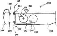
如图17所示,根据一种方案,通过提供使边撑臂元件202与横撑架元件204相连的上铰链234和下铰链236来实现边撑臂202上的电气部件与前框架204上的光源206的分离。上铰链234和下铰链236被用于提供正和负触点以在边撑臂元件202与横撑架元件204之间实现导电。在该实例中,第一导线238使上铰链234与来自电源232的正触点240相连并且第二导线242使下铰链236与来自电源232的负触点244相连。采用螺钉紧固件246枢转固定横撑架204和边撑臂元件202的上铰链234和下铰链236。而且,横撑架元件204上的导线使铰链234,236与横撑架元件204上的光源(多个光源)206电连接,例如在前和后层216,226中或之间的通道或凹槽内。如此构造,电源232通过边撑臂元件202与横撑架元件204之间的枢转连接件向光源206供电,而不必采用露出的导线或者随着重复使用和/或弯曲而被磨损的其他移动部件。 As shown in Figure 17, according to one solution, the electrical components on the
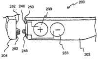
通过图18所示的另一方案,边撑臂元件202可以包括在其前表面250上的电触点248,并且横撑架元件204可以包括定位成在照明眼镜200处于使用或打开构造时与边撑臂元件202的电触点248接合的互补电触点252。通过另一方案,可以采用弹簧导线等代替触点248,252以使电连接件横跨在边撑臂元件202与横撑架元件204之间。类似于如上针对铰链234,236所述的,导线使触点252与横撑架元件204上的光源(多个光源)206电连接,例如在设置在前和后层216,226中或之间的通道或凹槽内。 By another approach shown in FIG. 18 , the
如图19所示,示出了变型的LED 306的放大图,其可以被用于照明眼镜100和/或200。变型的LED 306可以是任何常见的LED,包括常规透明材料和构造的壳体或镜片302、用于照明的LED芯片或二极管、从中延伸的电导线307,例如阳极好阴极导线。在所示形式中,变型的LED 306包括在其上的光改变涂层或表面308。该涂层可以被构造成使从LED 306投射的光扩散和柔和并且可以是任何适当的扩散涂层,包括例如磨砂层、喷砂表面、酸蚀刻表面、半透明涂层等等。如此构造,通过变型的LED 306发出的光得到改变、变得柔和或通过其他方式由层308改变。光改变涂层308还可以或者备选地被构造成模仿或仿效被用于构成横撑架元件104和/或边撑臂元件102的材料的颜色、纹理和/或外观。在另一形 式中,涂层308可以是折射涂层以按照需要聚焦或汇集从LED投射的光。在另一形式中,涂层308可以是波长或彩色滤光片或彩色涂层以从LED 306投射所需颜色的光。 As shown in FIG. 19 , a magnified view of a modified
本领域技术人员将会认识到,相对于上述实施方式在不脱离本发明的精神和范围的前提下可以做出多种修改、改变和组合,并且这些修改、改变和组合被认为是处于本发明构思的范围内。 Those skilled in the art will recognize that various modifications, changes and combinations can be made with respect to the above-mentioned embodiments without departing from the spirit and scope of the present invention, and these modifications, changes and combinations are considered to be within the scope of the present invention. within the scope of the idea. the
Claims (38)
Applications Claiming Priority (3)
| Application Number | Priority Date | Filing Date | Title |
|---|---|---|---|
| US30321210P | 2010-02-10 | 2010-02-10 | |
| US61/303,212 | 2010-02-10 | ||
| PCT/US2011/024400WO2011100471A1 (en) | 2010-02-10 | 2011-02-10 | Illuminated eyewear |
Publications (1)
| Publication Number | Publication Date |
|---|---|
| CN202199129Utrue CN202199129U (en) | 2012-04-25 |
Family
ID=44368123
Family Applications (1)
| Application Number | Title | Priority Date | Filing Date |
|---|---|---|---|
| CN2011900000016UExpired - LifetimeCN202199129U (en) | 2010-02-10 | 2011-02-10 | lighting glasses |
Country Status (10)
| Country | Link |
|---|---|
| US (2) | US8545012B2 (en) |
| EP (1) | EP2534531B1 (en) |
| CN (1) | CN202199129U (en) |
| AU (1) | AU2011215777B2 (en) |
| BR (1) | BR112012020050A8 (en) |
| CA (1) | CA2789493C (en) |
| ES (1) | ES2547907T3 (en) |
| MX (1) | MX2012009241A (en) |
| WO (1) | WO2011100471A1 (en) |
| ZA (1) | ZA201205932B (en) |
Cited By (2)
| Publication number | Priority date | Publication date | Assignee | Title |
|---|---|---|---|---|
| CN104035212A (en)* | 2014-06-23 | 2014-09-10 | 何东波 | color-changing glasses |
| CN112789548A (en)* | 2018-09-25 | 2021-05-11 | 依视路国际公司 | Ophthalmic device with blinking illumination element for reducing the effects of reading disturbances |
Families Citing this family (64)
| Publication number | Priority date | Publication date | Assignee | Title |
|---|---|---|---|---|
| US8388164B2 (en) | 2005-05-17 | 2013-03-05 | Michael Waters | Hands-Free lighting devices |
| US7661818B2 (en) | 2001-11-07 | 2010-02-16 | Michael Waters | Clip-on light apparatus |
| US8491118B2 (en) | 2001-11-07 | 2013-07-23 | Michael Waters | Lighted reading glasses |
| US8235524B2 (en) | 2001-11-07 | 2012-08-07 | Michael Waters | Illuminated eyewear |
| US8979295B2 (en) | 2005-05-17 | 2015-03-17 | Michael Waters | Rechargeable lighted glasses |
| US9526292B2 (en) | 2005-05-17 | 2016-12-27 | Michael Waters | Power modules and headgear |
| US20120176580A1 (en)* | 2005-10-11 | 2012-07-12 | Vanderbilt University | Electronics assembly in low-vision reader |
| US7699486B1 (en) | 2007-10-29 | 2010-04-20 | Edward Beiner | Illuminated eyeglass assembly |
| CA2753717C (en) | 2009-02-27 | 2016-07-12 | Michael Waters | Lighted hat |
| CN201796205U (en) | 2009-09-30 | 2011-04-13 | 迈克尔·沃特斯 | lighting glasses |
| MX2012009241A (en) | 2010-02-10 | 2012-09-07 | Michael Waters | Illuminated eyewear. |
| US8550649B2 (en)* | 2010-02-15 | 2013-10-08 | Webb T. Nelson | Stereoscopic illumination system for retroreflective materials |
| US8746914B2 (en) | 2010-02-15 | 2014-06-10 | Webb T. Nelson | Sports set that utilize stereoscopic illumination and retroreflective materials |
| CN202975580U (en) | 2010-04-30 | 2013-06-05 | 迈克尔·沃特斯 | Headgear and hat-mounted camera rig |
| US8540364B2 (en) | 2010-09-14 | 2013-09-24 | Michael Waters | Lighted glasses |
| EP2590009B1 (en)* | 2011-11-03 | 2016-03-09 | Fortuna Urbis S.r.l. | Eyeglasses |
| ES2577022T3 (en)* | 2011-11-03 | 2016-07-12 | Fortuna Urbis S.R.L. | Glasses |
| US9609902B2 (en) | 2011-12-23 | 2017-04-04 | Michael Waters | Headgear having a camera device |
| US9526287B2 (en) | 2011-12-23 | 2016-12-27 | Michael Waters | Lighted hat |
| USD682343S1 (en) | 2011-12-23 | 2013-05-14 | Michael Waters | Lighted glasses |
| US9568173B2 (en) | 2011-12-23 | 2017-02-14 | Michael Waters | Lighted hat |
| USD660902S1 (en) | 2012-02-02 | 2012-05-29 | Hasbro, Inc. | Vision apparatus |
| GB2499636A (en)* | 2012-02-23 | 2013-08-28 | Kelvin Chao-Fu He | Glasses having light-emitting diode illumination |
| WO2014100477A1 (en) | 2012-12-19 | 2014-06-26 | Michael Waters | Lighted solar hat |
| WO2014144507A1 (en) | 2013-03-15 | 2014-09-18 | Michael Waters | Lighted headgear |
| USD770143S1 (en) | 2014-05-23 | 2016-11-01 | Michael Waters | Beanie with means for illumination |
| CA2956795C (en) | 2014-08-03 | 2020-06-30 | PogoTec, Inc. | Wearable camera systems and apparatus and method for attaching camera systems or other electronic devices to wearable articles |
| US9635222B2 (en) | 2014-08-03 | 2017-04-25 | PogoTec, Inc. | Wearable camera systems and apparatus for aligning an eyewear camera |
| CN208041675U (en) | 2014-12-02 | 2018-11-02 | 迈克尔·沃特斯 | flashlight and communication device |
| USD824557S1 (en) | 2014-12-02 | 2018-07-31 | Michael Waters | Flashlight |
| CA2972064A1 (en) | 2014-12-23 | 2016-06-30 | PogoTec, Inc. | Wireless camera system and methods |
| GB2536650A (en) | 2015-03-24 | 2016-09-28 | Augmedics Ltd | Method and system for combining video-based and optic-based augmented reality in a near eye display |
| US10481417B2 (en) | 2015-06-10 | 2019-11-19 | PogoTec, Inc. | Magnetic attachment mechanism for electronic wearable device |
| EP3308216B1 (en) | 2015-06-10 | 2021-04-21 | Pogotec, Inc. | Eyewear with magnetic track for electronic wearable device |
| TW201729610A (en) | 2015-10-29 | 2017-08-16 | 帕戈技術股份有限公司 | Hearing aid adapted for wireless power reception |
| US11558538B2 (en) | 2016-03-18 | 2023-01-17 | Opkix, Inc. | Portable camera system |
| EP3539285A4 (en) | 2016-11-08 | 2020-09-02 | Pogotec, Inc. | A smart case for electronic wearable device |
| CN107202313A (en)* | 2017-06-16 | 2017-09-26 | 上海市格致初级中学 | Eyeglass lamp |
| EP3690519B1 (en)* | 2017-09-25 | 2023-12-13 | Mitsui Chemicals, Inc. | Frame component, temple, frame, and eyewear |
| US10935815B1 (en) | 2018-03-06 | 2021-03-02 | Snap Inc. | Eyewear having custom lighting |
| US11025892B1 (en) | 2018-04-04 | 2021-06-01 | James Andrew Aman | System and method for simultaneously providing public and private images |
| US11619834B2 (en) | 2018-04-25 | 2023-04-04 | William Allen | Illuminated lens frame |
| US11980507B2 (en) | 2018-05-02 | 2024-05-14 | Augmedics Ltd. | Registration of a fiducial marker for an augmented reality system |
| US10768451B1 (en)* | 2018-06-26 | 2020-09-08 | Snap Inc. | Diffusers in wearable devices |
| US20200110289A1 (en)* | 2018-10-03 | 2020-04-09 | Carlos de la Fuente | Ambient light adjustable eyeglasses |
| US11300857B2 (en) | 2018-11-13 | 2022-04-12 | Opkix, Inc. | Wearable mounts for portable camera |
| US11766296B2 (en) | 2018-11-26 | 2023-09-26 | Augmedics Ltd. | Tracking system for image-guided surgery |
| KR102827036B1 (en)* | 2019-02-22 | 2025-06-27 | 스냅 인코포레이티드 | Modular eyewear temples |
| US10791783B1 (en) | 2019-05-16 | 2020-10-06 | Waters Industries, Inc. | Lighted headgear and accessories therefor |
| US11980506B2 (en) | 2019-07-29 | 2024-05-14 | Augmedics Ltd. | Fiducial marker |
| US12178666B2 (en) | 2019-07-29 | 2024-12-31 | Augmedics Ltd. | Fiducial marker |
| WO2021108018A1 (en)* | 2019-11-27 | 2021-06-03 | Murata Manufacturing Co., Ltd. | Smart eyewear including electrochromic lenses |
| DE102020102281A1 (en)* | 2019-12-19 | 2021-06-24 | USound GmbH | Glasses with charging interface |
| US11382712B2 (en) | 2019-12-22 | 2022-07-12 | Augmedics Ltd. | Mirroring in image guided surgery |
| US11389252B2 (en) | 2020-06-15 | 2022-07-19 | Augmedics Ltd. | Rotating marker for image guided surgery |
| US12239385B2 (en) | 2020-09-09 | 2025-03-04 | Augmedics Ltd. | Universal tool adapter |
| US11896445B2 (en) | 2021-07-07 | 2024-02-13 | Augmedics Ltd. | Iliac pin and adapter |
| US12150821B2 (en) | 2021-07-29 | 2024-11-26 | Augmedics Ltd. | Rotating marker and adapter for image-guided surgery |
| WO2023021448A1 (en) | 2021-08-18 | 2023-02-23 | Augmedics Ltd. | Augmented-reality surgical system using depth sensing |
| US12171293B2 (en) | 2021-12-27 | 2024-12-24 | Waters Industries, Inc. | Lighted headgear and accessories therefor |
| EP4511809A1 (en) | 2022-04-21 | 2025-02-26 | Augmedics Ltd. | Systems and methods for medical image visualization |
| IL319523A (en) | 2022-09-13 | 2025-05-01 | Augmedics Ltd | Augmented reality eyewear for image-guided medical intervention |
| US12025854B1 (en)* | 2022-12-22 | 2024-07-02 | Cie Technologies Llc | Eyewear with circumambient illumination |
| DE102024109492A1 (en) | 2023-04-07 | 2024-10-10 | Milwaukee Electric Tool Corporation | PORTABLE NECK LAMP |
Family Cites Families (254)
| Publication number | Priority date | Publication date | Assignee | Title |
|---|---|---|---|---|
| US1572210A (en) | 1926-02-09 | Combined visor and automatic flash light | ||
| US1255265A (en) | 1916-04-12 | 1918-02-05 | Ladislaus Zachara | Electric spectacle lamp and frame. |
| US1261824A (en) | 1917-04-04 | 1918-04-09 | Henry La Vine | Portable electric light. |
| US1438586A (en) | 1920-03-18 | 1922-12-12 | Eaton Richard Max | Flash light |
| US1448353A (en) | 1921-12-21 | 1923-03-13 | Franco Electric Corp | Flash light |
| US1663402A (en) | 1925-10-09 | 1928-03-20 | Superloid Mfg Company Inc | Lens mounting |
| US1615067A (en) | 1926-04-15 | 1927-01-18 | Boerman Jacob | Inspection light |
| US1879512A (en) | 1931-07-07 | 1932-09-27 | Rotea Ireneo | Spectacle type of lamp holder |
| US2196543A (en) | 1938-05-16 | 1940-04-09 | William O Anderson | Automatic light for spectacles |
| US2531585A (en) | 1947-08-04 | 1950-11-28 | William H Pope | Combination flashlight, eyepiece, and headgear |
| US2461254A (en) | 1947-10-18 | 1949-02-08 | Gen Electric | Radiation filter |
| US2591112A (en) | 1948-04-27 | 1952-04-01 | Henry Hyman | Vest pocket flashlight, including electric system and lock subassembly |
| US2638532A (en) | 1949-03-23 | 1953-05-12 | Thomas L Brady | Combined spectacle frame and light |
| US2567046A (en) | 1950-06-09 | 1951-09-04 | Stewart R Brown Mfg Co Inc | Two-color wand light attachment for flashlights |
| US2904570A (en)* | 1956-03-27 | 1959-09-15 | Metal & Thermit Corp | Hydrocarbontin derivatives of trismercapto borate esters |
| US2904670A (en) | 1957-04-12 | 1959-09-15 | Calmes Andre | Illuminating spectacles |
| US3060308A (en) | 1959-05-08 | 1962-10-23 | Anton J Fortuna | Illuminated optical device |
| US2966580A (en) | 1959-09-24 | 1960-12-27 | Frank E Taylor | Battery hand lamp |
| US3350552A (en) | 1965-03-05 | 1967-10-31 | Paul A Lawrence | Illuminating device for a person's head |
| US3602759A (en) | 1966-10-12 | 1971-08-31 | Westinghouse Electric Corp | Electric lamp with protective enclosure having shrunk plastic retaining means |
| DE6925796U (en) | 1969-06-27 | 1969-12-04 | Joachim Tatje | GLASSES |
| US3647059A (en) | 1969-10-02 | 1972-03-07 | Thomas F Humphreys | Accessory receptacle |
| US3634676A (en) | 1970-03-23 | 1972-01-11 | Angelo Castellano | Combined spectacle frame and light |
| US3647069A (en)* | 1970-05-11 | 1972-03-07 | Robert S Bailey | Enclosed flotation apparatus and process |
| US3793517A (en) | 1971-09-20 | 1974-02-19 | A Carlini | Lighting device for a helmet or the like |
| US3769663A (en) | 1972-05-04 | 1973-11-06 | T Perl | Flashlight attachment clip for spectacles |
| US4210952A (en) | 1978-02-23 | 1980-07-01 | Ressmeyer Roger H | Portable illumination source for photographers |
| US4254451A (en) | 1978-10-27 | 1981-03-03 | Cochran James A Jun | Sequential flashing device for personal ornamentation |
| US4406040A (en) | 1978-11-27 | 1983-09-27 | Cannone Robert P | Illumination devices |
| US4283127A (en) | 1979-11-29 | 1981-08-11 | Marvin Glass & Associates | Novelty eyeglasses |
| US4332007A (en) | 1980-10-06 | 1982-05-25 | Jedco Products Limited, Inc. | Utility light |
| DE3043007A1 (en) | 1980-11-11 | 1982-06-16 | Charles Dr.med. Paris Freche | Magnifying observation spectacles with field of view illumination - has light source supplied by optical fibres in frame |
| US4462064A (en) | 1980-12-01 | 1984-07-24 | Schweitzer Robert B | Compact battery-powered headlamp |
| FR2520199A1 (en) | 1982-02-24 | 1983-07-29 | Cote Allan | APPARATUS AND METHOD FOR Raising the dough |
| US4516157A (en) | 1982-11-23 | 1985-05-07 | Campbell Malcolm G | Portable electronic camera |
| US4541698A (en) | 1983-06-20 | 1985-09-17 | Cine-Tech, Inc. | Remote camera viewfinder |
| AT383428B (en) | 1984-03-22 | 1987-07-10 | Goerike Rudolf | EYEGLASSES TO IMPROVE NATURAL HEARING |
| DE3426358A1 (en) | 1984-07-17 | 1986-01-23 | Patent-Treuhand-Gesellschaft für elektrische Glühlampen mbH, 8000 München | PORTABLE LIGHTING DEVICE |
| US4616297A (en) | 1985-10-18 | 1986-10-07 | Liu Ju Fu | Spectacles-like illuminating device |
| US5140220A (en) | 1985-12-02 | 1992-08-18 | Yumi Sakai | Light diffusion type light emitting diode |
| US4774643A (en) | 1986-11-17 | 1988-09-27 | Diagin, Inc. | Illuminator for radiation dosimeter and method of manufacture |
| US4963045A (en) | 1987-05-15 | 1990-10-16 | The Willcox Family Trust | Dispenser-applicator for spreading substances |
| DE3729588C1 (en) | 1987-09-04 | 1988-12-01 | Optyl Holding | Glasses frame with elastically deformable saddle bar |
| US4822161A (en) | 1988-01-19 | 1989-04-18 | Jimmy Michael F | Illuminating spectacle apparatus |
| CN88203065U (en)* | 1988-02-04 | 1988-11-09 | 任道宏 | Illuminated spectacles |
| US4822160A (en) | 1988-06-08 | 1989-04-18 | James Tsai | Flashing spectacles |
| US5331333A (en) | 1988-12-08 | 1994-07-19 | Sharp Kabushiki Kaisha | Display apparatus |
| US4959760A (en) | 1990-01-19 | 1990-09-25 | Te Sheng Wu | Lighting equipment for an eyeglasses |
| US5143443A (en) | 1990-08-31 | 1992-09-01 | Integrated Systems Engineering, Inc. | Light permeable, color adding, self-securing stressed covers for large display light-emitting devices, and methods |
| US5070436A (en) | 1990-10-29 | 1991-12-03 | Alexander Richard M | Signal vest, colored, reflective, and lighted, worn by persons seen on and nearby roadways and highways and other needed areas |
| US5164749A (en) | 1990-12-10 | 1992-11-17 | Opsales/Lenservice, Inc. | Clip for mounting sunglass lenses on spectacles |
| CA2059597A1 (en) | 1991-01-22 | 1992-07-23 | Paul A. Vogt | Radio eyewear |
| US5122943A (en) | 1991-04-15 | 1992-06-16 | Miles Inc. | Encapsulated light emitting diode and method for encapsulation |
| US5375044A (en) | 1991-05-13 | 1994-12-20 | Guritz; Steven P. W. | Multipurpose optical display for articulating surfaces |
| US5189512A (en) | 1991-07-01 | 1993-02-23 | Camair Research, Inc. | Helmet integrated display system |
| US5113325B1 (en) | 1991-08-01 | 1994-09-13 | Eisenbraun Reiss Inc | Light assembly kit for illuminating an article of clothing |
| US5158356A (en) | 1992-02-10 | 1992-10-27 | Guthrie Alan V | Ornamental lamp with internal switch |
| WO1996013136A1 (en) | 1992-02-14 | 1996-05-02 | Da Silva Jean Pierre M | Audio-adapted eyeglass retainer |
| US5367345A (en) | 1992-02-14 | 1994-11-22 | Da Silva Jean Pierre M | Audio-adapted eyeglass retainer |
| US5183326A (en) | 1992-02-25 | 1993-02-02 | Rcp Enterprises, Inc. | Underwater flashlight holder |
| US5218385A (en) | 1992-03-17 | 1993-06-08 | Lii Jein Hei | Flash light eyeglasses with hinge switch |
| US5245516A (en) | 1992-04-03 | 1993-09-14 | Haas Joan O De | Portable illumination device |
| USD343470S (en) | 1992-04-07 | 1994-01-18 | John Manufacturing Limited | Double torch |
| US5331357A (en) | 1992-07-31 | 1994-07-19 | Luxtec Corporation | Illumination assembly |
| USD349123S (en) | 1992-07-31 | 1994-07-26 | Luxtec Corporation | Spectacles having integral illumination |
| US5230558A (en) | 1992-09-24 | 1993-07-27 | Jong Chion B | Headlight |
| GB2272073A (en) | 1992-10-28 | 1994-05-04 | Hak Ngai Howard Ko | Spectacle frame with a radio and alarm clock |
| US5438698A (en) | 1992-12-14 | 1995-08-01 | Sweat Accessories, Inc. | Wearable audio reception device |
| US5278734A (en) | 1993-01-14 | 1994-01-11 | Ferber Andrew R | Light illuminating assemblies for wearing apparel with light element securement means |
| DE9307209U1 (en)* | 1993-05-12 | 1993-11-04 | Ottmann, Bernhard, 69234 Dielheim | READING AND ASSEMBLY GLASSES |
| US5452190A (en) | 1993-07-19 | 1995-09-19 | Priesemuth; Wolfgang | Optoelectronic component |
| US5546099A (en) | 1993-08-02 | 1996-08-13 | Virtual Vision | Head mounted display system with light blocking structure |
| ZA946001B (en) | 1993-08-11 | 1996-02-12 | Designodev Ltd | Flashlight adaptor |
| US5460346A (en) | 1993-10-05 | 1995-10-24 | Hirsch; Nathan | Article holder |
| AU686245B2 (en) | 1993-10-07 | 1998-02-05 | Virtual Vision, Inc. | Binocular head mounted display system |
| US5610678A (en) | 1993-12-30 | 1997-03-11 | Canon Kabushiki Kaisha | Camera including camera body and independent optical viewfinder |
| US5485358A (en) | 1994-05-18 | 1996-01-16 | Chien; Tseng L. | Universal L.E.D. safety light for head-wear |
| DE9410886U1 (en) | 1994-07-07 | 1994-09-15 | Wu, Der-Shan, Sertou Hsian, Changhua | Portable mini lighting device |
| US5836673A (en) | 1994-08-12 | 1998-11-17 | Lo; Robin | Strip sport light |
| US5541767A (en) | 1994-10-27 | 1996-07-30 | Designs For Vision, Inc. | Bioptic telescope system for use with bifocal spectacle |
| DE19507518C2 (en) | 1995-03-03 | 1999-01-28 | Albrecht Paul | Lamp with colored silicone cap |
| USD375372S (en) | 1995-03-21 | 1996-11-05 | Allen David M | Pocket flashlight |
| US5667292A (en) | 1995-05-03 | 1997-09-16 | Sabalvaro, Jr.; Valentin C. | Hat light |
| US5667291A (en) | 1995-05-23 | 1997-09-16 | Surgical Acuity, Inc. | Illumination assembly for dental and medical applications |
| JP3187280B2 (en) | 1995-05-23 | 2001-07-11 | シャープ株式会社 | Surface lighting device |
| US5541816A (en) | 1995-06-07 | 1996-07-30 | Miserendino; Nicholas G. | Clip light source |
| US5871271A (en) | 1995-11-30 | 1999-02-16 | Chien; Tseng Lu | LED illuminated protective headwear |
| USD383754S (en) | 1995-12-06 | 1997-09-16 | John Manufacturing Limited | Combination radio lantern |
| US6005536A (en) | 1996-01-16 | 1999-12-21 | National Captioning Institute | Captioning glasses |
| USD383863S (en) | 1996-02-21 | 1997-09-16 | John Manufacturing Limited | Flashlight |
| TW395121B (en) | 1996-02-26 | 2000-06-21 | Seiko Epson Corp | Personal wearing information display device and the display method using such device |
| US5806961A (en) | 1996-04-12 | 1998-09-15 | Eveready Battery Company, Inc. | Rechargeable flashlight assembly with nightlight |
| US5722762A (en) | 1996-07-18 | 1998-03-03 | Soll; David B. | Illumination device for mounting on the head of a user |
| US6012827A (en) | 1996-08-26 | 2000-01-11 | Surgical Acuity, Inc. | Mounting apparatus for head- and body- borne optics and illumination devices |
| US5741060A (en) | 1996-08-28 | 1998-04-21 | Johnson; Thomas R. | Baseball cap light |
| USD388113S (en) | 1996-10-11 | 1997-12-23 | Designs For Vision, Inc. | Combined eyeglasses and mounted headlight |
| US6012822A (en) | 1996-11-26 | 2000-01-11 | Robinson; William J. | Motion activated apparel flasher |
| US5997165A (en) | 1997-04-24 | 1999-12-07 | Lehrer; Robert A. | Portable reading light device |
| US5893631A (en) | 1997-11-03 | 1999-04-13 | Padden; Stephen J. | Compact flashlight |
| EP0952500B1 (en) | 1997-11-20 | 2006-12-27 | Seiko Epson Corporation | Electronic device and method for controlling electronic device |
| JPH11164186A (en) | 1997-11-27 | 1999-06-18 | Fuji Photo Film Co Ltd | Image recorder |
| US6056413A (en) | 1997-12-29 | 2000-05-02 | Urso; Charles L. | Cap lamp |
| USD405901S (en) | 1998-04-13 | 1999-02-16 | Designs For Vision, Inc. | Clip-on headlight for an eyeglass frame |
| US5946071A (en) | 1998-07-14 | 1999-08-31 | Live Wire Enterprises, Inc. | Eyeglasses with illuminated frame |
| US6086214A (en) | 1998-08-27 | 2000-07-11 | Ridge; Philip G. | Wind powered lamp |
| US6174075B1 (en) | 1998-10-28 | 2001-01-16 | Luminary Logic Ltd | Illuminated ornamentation/amusement device |
| USD420035S (en) | 1998-12-21 | 2000-02-01 | Hartman James L | Eyeglasses |
| USD446324S1 (en) | 1999-04-05 | 2001-08-07 | Eveready Battery Company, Inc. | Squeeze light |
| US6290368B1 (en) | 1999-05-21 | 2001-09-18 | Robert A. Lehrer | Portable reading light device |
| WO2000074177A1 (en) | 1999-05-28 | 2000-12-07 | Krone Digital Communications, Inc. | Cable assembly with molded stress relief and method for making the same |
| US6367949B1 (en) | 1999-08-04 | 2002-04-09 | 911 Emergency Products, Inc. | Par 36 LED utility lamp |
| AU6911100A (en) | 1999-08-16 | 2001-03-13 | Emissive Energy Corporation | Miniature flashlight |
| US6530672B2 (en) | 1999-08-16 | 2003-03-11 | Robert D. Galli | Miniature flashlight |
| US7052154B2 (en) | 2003-06-25 | 2006-05-30 | Vanderschuit Carl R | Lighted hat |
| US6302570B1 (en) | 1999-10-14 | 2001-10-16 | Fiber Optic Design, Inc. | Compact illumination device using optical fibers |
| US6206543B1 (en) | 1999-11-12 | 2001-03-27 | David Vincent Henry | Flashlight holder assembly |
| USD428431S (en) | 2000-01-14 | 2000-07-18 | Jordan Le Roy L | Illuminating glasses |
| US6554444B2 (en) | 2000-03-13 | 2003-04-29 | Kansai Technology Licensing Organization Co., Ltd. | Gazing point illuminating device |
| US6311837B1 (en) | 2000-03-28 | 2001-11-06 | The Procter & Gamble Company | Packaging arrangement having recesses for preventing a switch from being placed in a continuously-on position |
| AU2001253190A1 (en) | 2000-04-05 | 2001-10-23 | David M. Allen | Portable illumination device |
| US7278734B2 (en) | 2000-06-02 | 2007-10-09 | Oakley, Inc. | Wireless interactive headset |
| US7150526B2 (en) | 2000-06-02 | 2006-12-19 | Oakley, Inc. | Wireless interactive headset |
| US6390640B1 (en) | 2000-07-06 | 2002-05-21 | American Underwater Products Inc. | Lighted mask for underwater divers |
| US6439738B1 (en) | 2000-08-02 | 2002-08-27 | Surefire, Llc | Battery powered portable electric light source systems |
| US6299323B1 (en) | 2000-10-13 | 2001-10-09 | Sun Yu | Miniature led flashlight |
| USD445928S1 (en) | 2000-12-11 | 2001-07-31 | Streamlight, Inc. | Keylight |
| US6461025B1 (en) | 2000-12-14 | 2002-10-08 | Infocus Corp | Lamp assembly with snap fit components |
| TW572348U (en) | 2001-01-15 | 2004-01-11 | Shining Blick Enterprises Co | Safety protection device for bulb with polarity leads directly bonded to conductive wires |
| US6601984B2 (en) | 2001-02-14 | 2003-08-05 | Estec Co., Ltd. | LED illuminating device and lighting apparatus employing the same |
| US6386701B1 (en) | 2001-04-03 | 2002-05-14 | Basimah Khulusi Md, Llc | Eyewear for relief of computer vision syndrome |
| US6733150B1 (en) | 2001-04-20 | 2004-05-11 | Edward B. Hanley | Headgear with forward illumination |
| US7234831B1 (en) | 2001-04-20 | 2007-06-26 | Hanley Edward B | Headgear with forward illumination |
| US6719437B2 (en) | 2001-04-25 | 2004-04-13 | Banning Lary | Head apparatus with light emitting diodes |
| US6474830B1 (en) | 2001-05-04 | 2002-11-05 | Enlighted Designs, Inc. | Multi-purpose illumination device adaptable for use as a button fastener |
| KR100420279B1 (en) | 2001-06-07 | 2004-03-02 | 삼성전자주식회사 | Portable communication device for minimizing sar value |
| DE10132872B4 (en) | 2001-07-06 | 2018-10-11 | Volkswagen Ag | Head mounted optical inspection system |
| US6713956B2 (en) | 2001-07-24 | 2004-03-30 | Lite-On Technology Corporation | Display module including a plate for heat dissipation and shielding |
| US6604837B2 (en) | 2001-08-03 | 2003-08-12 | Robert J. Sandberg | Device for holding a light source |
| US6808284B1 (en) | 2001-08-16 | 2004-10-26 | Contour Optik, Inc. | Eyeglasses provided with light sources, screw drivers, and writing instruments |
| USD457670S1 (en) | 2001-08-31 | 2002-05-21 | David Allen | X-light personal flashlight |
| CA2360186C (en) | 2001-10-26 | 2008-08-05 | Anthony Derose | Improvements in display signs, decorative lighting and ornaments for holiday seasons |
| US6612695B2 (en) | 2001-11-07 | 2003-09-02 | Michael Waters | Lighted reading glasses |
| US8491118B2 (en) | 2001-11-07 | 2013-07-23 | Michael Waters | Lighted reading glasses |
| US7661818B2 (en)* | 2001-11-07 | 2010-02-16 | Michael Waters | Clip-on light apparatus |
| US8235524B2 (en) | 2001-11-07 | 2012-08-07 | Michael Waters | Illuminated eyewear |
| US8388164B2 (en)* | 2005-05-17 | 2013-03-05 | Michael Waters | Hands-Free lighting devices |
| US6888502B2 (en) | 2002-03-05 | 2005-05-03 | Precision Dynamics Corporation | Microstrip antenna for an identification appliance |
| USD469198S1 (en) | 2002-03-28 | 2003-01-21 | Multi-Media Electronics, Inc. | Strobe light |
| US20030189824A1 (en) | 2002-04-03 | 2003-10-09 | Meeder Torre J. | Portable reading light |
| USD477432S1 (en) | 2002-05-06 | 2003-07-15 | Armament Systems And Prodecures, Inc. | Flashlight |
| US6811441B2 (en) | 2002-05-10 | 2004-11-02 | Fci Americas Technology, Inc. | Electrical cable strain relief and electrical closure |
| USD473890S1 (en) | 2002-05-28 | 2003-04-29 | Michael Waters | Lighted eyeglasses |
| US20030221267A1 (en) | 2002-05-30 | 2003-12-04 | The Procter & Gamble Co. | Electric toothbrushes and packages containing same |
| AUPS327002A0 (en)* | 2002-06-28 | 2002-07-18 | Kabay & Company Pty Ltd | An electroluminescent light emitting device |
| US6860628B2 (en) | 2002-07-17 | 2005-03-01 | Jonas J. Robertson | LED replacement for fluorescent lighting |
| CN1720763B (en) | 2002-07-26 | 2013-06-12 | 奥克利有限公司 | Glasses |
| US6764194B1 (en) | 2002-08-09 | 2004-07-20 | Ira J. Cooper | Headlight with universal mounting |
| RU2005111763A (en) | 2002-09-20 | 2005-09-20 | Колгейт-Палмолив Компани (US) | THE ELECTRIC TOOTHBRUSH |
| US6802636B1 (en) | 2002-09-30 | 2004-10-12 | Richard B Bailey, Jr. | Illuminated recreational board |
| US6749166B2 (en) | 2002-11-13 | 2004-06-15 | Mike Valentine | Flashlight holder |
| US7003353B1 (en) | 2002-12-10 | 2006-02-21 | Quallion Llc | Photovoltaic powered charging apparatus for implanted rechargeable batteries |
| US7008074B1 (en) | 2002-12-10 | 2006-03-07 | Halm Gary V | Hands-free controlled light operation |
| US6830357B2 (en) | 2002-12-20 | 2004-12-14 | Gerardo Lopez | Illuminated holiday vehicle wreath |
| JP2004207580A (en) | 2002-12-26 | 2004-07-22 | Rohm Co Ltd | Semiconductor light emitting device |
| IL153895A (en) | 2003-01-12 | 2013-01-31 | Orion Solar Systems Ltd | Solar cell device |
| KR200312151Y1 (en) | 2003-01-22 | 2003-05-09 | 주식회사 나스켐 | Utensil for radiation of clip type |
| US7281826B2 (en) | 2003-01-24 | 2007-10-16 | Gem Optical Co., Ltd. | Headband with magnifying lens and detachable light |
| US7633681B2 (en) | 2003-03-26 | 2009-12-15 | Intercast Usa, Inc. | Multilayer interference filter for photochromic lenses |
| US6824265B1 (en)* | 2003-03-31 | 2004-11-30 | Wesley Stephen Harper | Illuminated safety and work glasses |
| US7255437B2 (en) | 2003-10-09 | 2007-08-14 | Howell Thomas A | Eyeglasses with activity monitoring |
| US7806525B2 (en) | 2003-10-09 | 2010-10-05 | Ipventure, Inc. | Eyeglasses having a camera |
| US20050001433A1 (en) | 2003-04-30 | 2005-01-06 | Seelink Technology Corporation | Display system having uniform luminosity and wind generator |
| US7105939B2 (en) | 2003-05-08 | 2006-09-12 | Motion Charge, Inc. | Electrical generator having an oscillator containing a freely moving internal element to improve generator effectiveness |
| WO2005008804A2 (en) | 2003-05-08 | 2005-01-27 | Power Estimate Company | Apparatus and method for providing electrical energy generated from motion to an electrically powered device |
| TW581378U (en) | 2003-05-16 | 2004-03-21 | Hon Hai Prec Ind Co Ltd | Battery cover connected with a housing for a communication unit |
| US20040240204A1 (en) | 2003-05-29 | 2004-12-02 | Wray Russ | Electric flare |
| US7021790B2 (en) | 2003-07-22 | 2006-04-04 | Armament Systems & Procedures, Inc. | Miniature LED flashlight with snap-on carrier |
| US6966668B2 (en) | 2003-11-07 | 2005-11-22 | Noah Systems, Llc | Wearable light device with optical sensor |
| US20050099799A1 (en) | 2003-11-07 | 2005-05-12 | Mario Cugini | Wearable light device with optical sensor |
| USD501266S1 (en) | 2004-01-13 | 2005-01-25 | Brookstone Purchasing, Inc. | Flashlight |
| US7094981B2 (en) | 2004-01-23 | 2006-08-22 | Colgate-Palmolive Company | Powered toothbrush with test button |
| CN2641675Y (en) | 2004-01-29 | 2004-09-15 | 王兴根 | Luminous glasses |
| US20050211187A1 (en) | 2004-03-12 | 2005-09-29 | Harman Larry L | Control station with integrated collar recharging docking station for pet electronics products |
| US7111956B2 (en) | 2004-04-05 | 2006-09-26 | Light-On, Llc | Apparatuses and methods for vision assistance |
| US20050248932A1 (en) | 2004-05-07 | 2005-11-10 | Michael Waters | Clip-on light apparatus |
| US20050265015A1 (en) | 2004-05-14 | 2005-12-01 | Salazar Tracy A | Lighted bicycle helmet |
| US20050254238A1 (en) | 2004-05-14 | 2005-11-17 | Parker David H | Holder for a flashlight |
| US6857739B1 (en) | 2004-06-08 | 2005-02-22 | Peter Watson | Illuminated eyewear and a method for illuminating eyewear |
| DE102004053128A1 (en) | 2004-07-16 | 2006-02-09 | Osram Opto Semiconductors Gmbh | Sports glasses with increased visibility |
| US20060012974A1 (en)* | 2004-07-16 | 2006-01-19 | Chi-Yang Su | Multifunctional glasses |
| US7118262B2 (en) | 2004-07-23 | 2006-10-10 | Cree, Inc. | Reflective optical elements for semiconductor light emitting devices |
| US8337013B2 (en) | 2004-07-28 | 2012-12-25 | Ipventure, Inc. | Eyeglasses with RFID tags or with a strap |
| US7329982B2 (en) | 2004-10-29 | 2008-02-12 | 3M Innovative Properties Company | LED package with non-bonded optical element |
| US20060092621A1 (en) | 2004-10-29 | 2006-05-04 | Lai Marcos Y S | Tailpipe decoration |
| USD507368S1 (en) | 2004-11-10 | 2005-07-12 | Michael Waters | Dual light module |
| USD507369S1 (en) | 2004-11-10 | 2005-07-12 | Michael Waters | Light module |
| CN1603677A (en) | 2004-11-17 | 2005-04-06 | 何永新 | Hand-operated self-generating electric torch |
| US6997552B1 (en)* | 2004-11-23 | 2006-02-14 | Ming-Chi Hung | Light-emitting eyeglasses structure |
| US7390978B2 (en) | 2004-12-23 | 2008-06-24 | Motorola, Inc. | Overmolded electronic assembly and overmoldable interface component |
| JP2006186158A (en) | 2004-12-28 | 2006-07-13 | Sharp Corp | Light emitting diode lamp and light emitting diode display device |
| US20060158895A1 (en) | 2005-01-14 | 2006-07-20 | Brands David C | LED flashlight |
| CN2826472Y (en) | 2005-02-16 | 2006-10-11 | 吕晓建 | illuminated glasses |
| US20060198122A1 (en) | 2005-03-04 | 2006-09-07 | R2 Innovation Llc | Illuminated headwear |
| US20060197905A1 (en) | 2005-03-07 | 2006-09-07 | Hsiao-Chien Lu | Eyeglasses equipped with lamp circuit assembly |
| US20060232239A1 (en) | 2005-04-18 | 2006-10-19 | Mag Instrument, Inc. | Flashlight charger with an improved contact |
| US20060239018A1 (en) | 2005-04-22 | 2006-10-26 | Dei Headquarters, Inc. | Display system using wheel-mounted strips of flashing lights |
| US20060238995A1 (en) | 2005-04-25 | 2006-10-26 | Kuei-Hsueh Wang | Snow goggles |
| US8979295B2 (en) | 2005-05-17 | 2015-03-17 | Michael Waters | Rechargeable lighted glasses |
| CA2608746C (en) | 2005-05-17 | 2014-12-23 | Michael Waters | Hands-free lighting devices |
| US20060291193A1 (en) | 2005-06-24 | 2006-12-28 | Roy Hill | Illuminating garment system and method of use |
| US7438409B2 (en)* | 2005-07-15 | 2008-10-21 | Jordan Lonnie Leroy | Illuminated reading glasses |
| USD568922S1 (en) | 2005-08-02 | 2008-05-13 | Ic! Berlin Brillen Gmbh | Spectacles |
| JP5133883B2 (en) | 2005-08-11 | 2013-01-30 | スリープ・ダイアグノスティックス・プロプライアタリー・リミテッド | Arousal detection glasses |
| US7226180B2 (en) | 2005-08-22 | 2007-06-05 | Hsiu-Ying Sung | Pair of shining swimming goggles |
| US20070074752A1 (en) | 2005-09-05 | 2007-04-05 | Shau Albert Y | Electrical power generators |
| US20070053179A1 (en) | 2005-09-08 | 2007-03-08 | Pang Slew I | Low profile light source utilizing a flexible circuit carrier |
| US7566140B2 (en) | 2005-09-09 | 2009-07-28 | Sevilla Ii Frederick J | Self illuminating belt buckle |
| US7942522B2 (en) | 2005-09-29 | 2011-05-17 | Vanderbilt University | Illuminated low-vision spectacles |
| US20120176580A1 (en) | 2005-10-11 | 2012-07-12 | Vanderbilt University | Electronics assembly in low-vision reader |
| GB0522650D0 (en) | 2005-11-07 | 2005-12-14 | Avecia Inkjet Ltd | Toner and process therefor |
| CN2861709Y (en) | 2005-12-23 | 2007-01-24 | 明高五金制品(深圳)有限公司 | Torsion mode self-generating energy-storage flashlight |
| US7327046B2 (en) | 2005-12-23 | 2008-02-05 | Alexander Benjamin Biamonte | Kinetic energy system and apparatus for charging portable batteries |
| US7309141B2 (en) | 2006-01-05 | 2007-12-18 | Resetone, Inc. | Air actuated decoration system and device |
| US20090190026A1 (en) | 2006-01-11 | 2009-07-30 | Leo Chen | Pair of Spectacles with Miniature Camera |
| US7722205B2 (en) | 2006-01-12 | 2010-05-25 | Surefire, Llc | Headgear light |
| US7784935B2 (en) | 2006-01-20 | 2010-08-31 | Jackson Michael T | Eyewear with removable audio system |
| US7495835B2 (en) | 2006-02-13 | 2009-02-24 | Ronald Daley | Display novelty |
| US7422324B2 (en) | 2006-02-28 | 2008-09-09 | Ching-Hui Lee | Illuminating device of eyeglasses |
| US7458699B2 (en) | 2006-03-03 | 2008-12-02 | Rawlings Sporting Goods Company, Inc. | Ball glove having impact detection and visible annunciation |
| US20070236915A1 (en) | 2006-04-06 | 2007-10-11 | Deen Chen | Led flickering shoes |
| US20070236916A1 (en) | 2006-04-11 | 2007-10-11 | Shu-Ching Hsu | Ligheing emitting devices used in knickers and brassiere |
| TWM300306U (en) | 2006-04-11 | 2006-11-01 | Gazelle Corp | Structure of the nose-fixture and the nose-pad of glasses |
| USD553177S1 (en) | 2006-04-21 | 2007-10-16 | Leo Chen | Eyeglass |
| NZ549912A (en)* | 2006-09-14 | 2009-07-31 | Phitek Systems Ltd | Battery Door |
| US7543934B2 (en) | 2006-09-20 | 2009-06-09 | Ipventures, Inc. | Eyeglasses with activity monitoring and acoustic dampening |
| CA2610073A1 (en) | 2006-11-08 | 2008-05-08 | Michael Waters | Clip-on light apparatus |
| KR100904764B1 (en) | 2007-08-20 | 2009-06-29 | 이건테크놀로지 주식회사 | Glasses with illumination function |
| US7699486B1 (en) | 2007-10-29 | 2010-04-20 | Edward Beiner | Illuminated eyeglass assembly |
| JP3142026U (en) | 2007-11-28 | 2008-06-05 | 正憲 田浦 | Temple with illuminated glasses |
| USD611086S1 (en) | 2008-02-26 | 2010-03-02 | Mr. Christmas Incorporated | Illuminating eyeglasses |
| US7607775B2 (en)* | 2008-02-26 | 2009-10-27 | Mr. Christmas Incorporated | Illuminating eyeglasses and eyeglasses frame structure |
| USD600738S1 (en) | 2008-11-04 | 2009-09-22 | Nvidia Corporation | 3-D stereo glasses |
| CN201796205U (en) | 2009-09-30 | 2011-04-13 | 迈克尔·沃特斯 | lighting glasses |
| CN201548769U (en) | 2009-10-21 | 2010-08-11 | 舒畅 | Eyeglasses |
| USD617826S1 (en) | 2010-01-14 | 2010-06-15 | Michael Waters | Lighted eyeglasses |
| MX2012009241A (en) | 2010-02-10 | 2012-09-07 | Michael Waters | Illuminated eyewear. |
| CN201707513U (en) | 2010-04-12 | 2011-01-12 | 金德发 | Spectacles with luminous function |
| US7997724B1 (en)* | 2010-05-28 | 2011-08-16 | Sun And Young Sunglasses Co., Ltd. | Illuminated eyeglass |
| US7946705B1 (en) | 2010-06-30 | 2011-05-24 | Sun And Young Sunglasses Co., Ltd. | Rechargeable illuminated eyeglasses |
| US8007101B1 (en) | 2010-08-26 | 2011-08-30 | Day Sun Industrial Corp. | Eyeglasses equipped with lighting devices |
| US20120050667A1 (en) | 2010-08-30 | 2012-03-01 | Ching-Hsiang Wang | Eyeglasses Capable of Being Recharged and Providing Three-Stage Lighting |
| US8540364B2 (en) | 2010-09-14 | 2013-09-24 | Michael Waters | Lighted glasses |
| USD682343S1 (en) | 2011-12-23 | 2013-05-14 | Michael Waters | Lighted glasses |
| CA3167661A1 (en) | 2012-01-06 | 2013-07-11 | E-Vision Smart Optics, Inc. | Eyewear docking station and electronic module |
- 2011
- 2011-02-10MXMX2012009241Apatent/MX2012009241A/enactiveIP Right Grant
- 2011-02-10CNCN2011900000016Upatent/CN202199129U/ennot_activeExpired - Lifetime
- 2011-02-10USUS13/025,100patent/US8545012B2/enactiveActive
- 2011-02-10CACA2789493Apatent/CA2789493C/enactiveActive
- 2011-02-10EPEP11742818.5Apatent/EP2534531B1/ennot_activeNot-in-force
- 2011-02-10BRBR112012020050Apatent/BR112012020050A8/ennot_activeIP Right Cessation
- 2011-02-10AUAU2011215777Apatent/AU2011215777B2/ennot_activeCeased
- 2011-02-10WOPCT/US2011/024400patent/WO2011100471A1/enactiveApplication Filing
- 2011-02-10ESES11742818.5Tpatent/ES2547907T3/enactiveActive
- 2012
- 2012-08-07ZAZA2012/05932Apatent/ZA201205932B/enunknown
- 2013
- 2013-09-26USUS14/038,301patent/US9513495B2/ennot_activeExpired - Fee Related
Cited By (4)
| Publication number | Priority date | Publication date | Assignee | Title |
|---|---|---|---|---|
| CN104035212A (en)* | 2014-06-23 | 2014-09-10 | 何东波 | color-changing glasses |
| CN112789548A (en)* | 2018-09-25 | 2021-05-11 | 依视路国际公司 | Ophthalmic device with blinking illumination element for reducing the effects of reading disturbances |
| CN112789548B (en)* | 2018-09-25 | 2023-08-11 | 依视路国际公司 | Ophthalmic device for reducing the impact of dyslexia with blinking lighting elements |
| US12117672B2 (en) | 2018-09-25 | 2024-10-15 | Essilor International | Ophthalmic device with a blinking illuminating element for reducing dyslexia effects |
Also Published As
| Publication number | Publication date |
|---|---|
| BR112012020050A2 (en) | 2018-03-20 |
| AU2011215777B2 (en) | 2015-11-26 |
| WO2011100471A1 (en) | 2011-08-18 |
| AU2011215777A1 (en) | 2012-09-06 |
| ZA201205932B (en) | 2013-05-29 |
| US9513495B2 (en) | 2016-12-06 |
| EP2534531A1 (en) | 2012-12-19 |
| EP2534531A4 (en) | 2014-10-01 |
| ES2547907T3 (en) | 2015-10-09 |
| US20140022765A1 (en) | 2014-01-23 |
| CA2789493A1 (en) | 2011-08-18 |
| BR112012020050A8 (en) | 2018-04-24 |
| EP2534531B1 (en) | 2015-09-16 |
| US8545012B2 (en) | 2013-10-01 |
| MX2012009241A (en) | 2012-09-07 |
| US20110187989A1 (en) | 2011-08-04 |
| CA2789493C (en) | 2019-02-26 |
Similar Documents
| Publication | Publication Date | Title |
|---|---|---|
| CN202199129U (en) | lighting glasses | |
| US8979295B2 (en) | Rechargeable lighted glasses | |
| US8567945B2 (en) | Illuminated eyewear | |
| US8235524B2 (en) | Illuminated eyewear | |
| US8491118B2 (en) | Lighted reading glasses | |
| US7938553B1 (en) | Illuminated eyeglass assembly | |
| US6824265B1 (en) | Illuminated safety and work glasses | |
| WO2009108767A1 (en) | Illuminating eyeglasses and eyeglasses frame structure | |
| CA2404230A1 (en) | Lighted writing support and clipboard | |
| JP2010537380A (en) | Glasses with lighting function | |
| HK1153278B (en) | Illuminated eyewear | |
| JP2000125933A (en) | Cosmetic compact with illumination | |
| WO2007008062A1 (en) | Spectacle frame having provisions for illuminating objects |
Legal Events
| Date | Code | Title | Description |
|---|---|---|---|
| C14 | Grant of patent or utility model | ||
| GR01 | Patent grant | ||
| CX01 | Expiry of patent term | Granted publication date:20120425 | |
| CX01 | Expiry of patent term |