CN202173242U - pressure cooker lid - Google Patents
pressure cooker lidDownload PDFInfo
- Publication number
- CN202173242U CN202173242UCN2011202595672UCN201120259567UCN202173242UCN 202173242 UCN202173242 UCN 202173242UCN 2011202595672 UCN2011202595672 UCN 2011202595672UCN 201120259567 UCN201120259567 UCN 201120259567UCN 202173242 UCN202173242 UCN 202173242U
- Authority
- CN
- China
- Prior art keywords
- valve
- pot cover
- knob
- pressure
- cover main
- Prior art date
- Legal status (The legal status is an assumption and is not a legal conclusion. Google has not performed a legal analysis and makes no representation as to the accuracy of the status listed.)
- Expired - Fee Related
Links
- 230000007246mechanismEffects0.000claimsabstractdescription21
- 238000006073displacement reactionMethods0.000claimsdescription3
- 238000007789sealingMethods0.000claimsdescription3
- 230000008520organizationEffects0.000claims2
- 210000000078clawAnatomy0.000abstractdescription17
- 238000010586diagramMethods0.000description8
- 230000009471actionEffects0.000description6
- 230000006872improvementEffects0.000description3
- 230000001276controlling effectEffects0.000description2
- 230000000875corresponding effectEffects0.000description2
- 238000000034methodMethods0.000description2
- 230000009286beneficial effectEffects0.000description1
- 230000008859changeEffects0.000description1
- 230000008602contractionEffects0.000description1
- 230000008569processEffects0.000description1
Images


Classifications
- A—HUMAN NECESSITIES
- A47—FURNITURE; DOMESTIC ARTICLES OR APPLIANCES; COFFEE MILLS; SPICE MILLS; SUCTION CLEANERS IN GENERAL
- A47J—KITCHEN EQUIPMENT; COFFEE MILLS; SPICE MILLS; APPARATUS FOR MAKING BEVERAGES
- A47J27/00—Cooking-vessels
- A47J27/08—Pressure-cookers; Lids or locking devices specially adapted therefor
- A47J27/09—Safety devices
- A—HUMAN NECESSITIES
- A47—FURNITURE; DOMESTIC ARTICLES OR APPLIANCES; COFFEE MILLS; SPICE MILLS; SUCTION CLEANERS IN GENERAL
- A47J—KITCHEN EQUIPMENT; COFFEE MILLS; SPICE MILLS; APPARATUS FOR MAKING BEVERAGES
- A47J27/00—Cooking-vessels
- A47J27/08—Pressure-cookers; Lids or locking devices specially adapted therefor
- A47J27/0802—Control mechanisms for pressure-cookers
- A—HUMAN NECESSITIES
- A47—FURNITURE; DOMESTIC ARTICLES OR APPLIANCES; COFFEE MILLS; SPICE MILLS; SUCTION CLEANERS IN GENERAL
- A47J—KITCHEN EQUIPMENT; COFFEE MILLS; SPICE MILLS; APPARATUS FOR MAKING BEVERAGES
- A47J27/00—Cooking-vessels
- A47J27/08—Pressure-cookers; Lids or locking devices specially adapted therefor
- A47J27/0804—Locking devices
- A47J27/0813—Locking devices using a clamping ring or clamping segments
- Y—GENERAL TAGGING OF NEW TECHNOLOGICAL DEVELOPMENTS; GENERAL TAGGING OF CROSS-SECTIONAL TECHNOLOGIES SPANNING OVER SEVERAL SECTIONS OF THE IPC; TECHNICAL SUBJECTS COVERED BY FORMER USPC CROSS-REFERENCE ART COLLECTIONS [XRACs] AND DIGESTS
- Y10—TECHNICAL SUBJECTS COVERED BY FORMER USPC
- Y10T—TECHNICAL SUBJECTS COVERED BY FORMER US CLASSIFICATION
- Y10T29/00—Metal working
- Y10T29/49—Method of mechanical manufacture
- Y10T29/49826—Assembling or joining
Landscapes
- Engineering & Computer Science (AREA)
- Food Science & Technology (AREA)
- Cookers (AREA)
Abstract
Description
Translated fromChinese技术领域technical field
本实用新型涉及一种压力锅锅盖。The utility model relates to a pressure cooker cover.
背景技术Background technique
对于采用旋钮-扣爪式结构的压力锅锅盖,用户转动锅盖上的旋钮即可控制扣爪的开合盖动作。如果需要在该锅盖上增设其他可调机构,例如工作压力可调的弹簧杆式限压阀,则锅盖上还需要增设相应的动作机构来调节该限压阀的工作压力。这样一来会导致锅盖的结构过于复杂,且用户使用起来也不方便。For a pressure cooker lid with a knob-claw structure, the user can control the opening and closing action of the clasp by turning the knob on the lid. If it is necessary to set up other adjustable mechanisms on the pot cover, such as a spring rod type pressure limiting valve with adjustable working pressure, then a corresponding action mechanism needs to be added on the pot cover to adjust the working pressure of the pressure limiting valve. This will cause the structure of the pot cover to be too complicated, and it is also inconvenient for users to use.
发明内容Contents of the invention
本实用新型解决的技术问题是提供一种结构简单,使用方便的压力锅锅盖,该锅盖的旋钮机构可以实现两个以上机构的动作控制。The technical problem solved by the utility model is to provide a pressure cooker lid with simple structure and convenient use. The knob mechanism of the lid can realize the action control of more than two mechanisms.
为解决上述技术问题,本实用新型采用的技术方案是:一种压力锅锅盖,该锅盖包括锅盖主体、扣爪和用于控制该扣爪沿锅盖主体径向移动的控制机构,该控制机构包括:外端与该扣爪固定连接的连接臂,用于驱动该连接臂沿锅盖主体径向移动的转盘,以及用于驱动该转盘转动的旋钮机构,其中:所述旋钮机构包括旋钮盖和限压阀,该旋钮盖带动所述转盘转动并驱动该限压阀的阀杆沿轴向移动以调整该限压阀的工作压力In order to solve the above technical problems, the technical solution adopted by the utility model is: a pressure cooker lid, the lid includes a lid body, a claw and a control mechanism for controlling the claw to move radially along the body of the lid. The control mechanism includes: a connecting arm whose outer end is fixedly connected to the claw, a turntable for driving the connecting arm to move radially along the main body of the pot cover, and a knob mechanism for driving the turntable to rotate, wherein: the knob mechanism includes Knob cover and pressure limiting valve, the knob cover drives the turntable to rotate and drives the valve stem of the pressure limiting valve to move axially to adjust the working pressure of the pressure limiting valve
改进之一:所述转盘上设有滑槽,该滑槽包括与所述锅盖主体同心的圆弧段和有径向位移的第二弧段,所述连接臂的内端设有与该滑槽配合的凸柱。One of the improvements: the turntable is provided with a chute, the chute includes a circular arc section concentric with the main body of the pot cover and a second arc section with radial displacement, the inner end of the connecting arm is provided with the Boss for chute fit.
改进之二:所述第二弧段的初始端与锅盖主体中心的径向距离大于其结束端与锅盖主体中心的径向距离,且所述第二弧段的结束端与所述圆弧段的初始端连接。Improvement 2: The radial distance between the initial end of the second arc segment and the center of the main body of the pot cover is greater than the radial distance between the end end of the second arc segment and the center of the main body of the pot cover, and the end end of the second arc segment is closer to the center of the circle The initial end connection of the arc segment.
改进之三:所述限压阀包括穿设于锅盖主体中的阀体,该阀体设有用于容置所述阀杆的阀腔,所述阀杆的下部设有与该阀腔底部的阀口配合的密封部,该阀体中还设有阀杆复位弹簧,该复位弹簧上端顶在所述旋钮盖的推杆部上,且所述旋钮盖与该阀体螺纹连接。当旋钮盖旋转向下时,其会推动复位弹簧和阀杆同步向下移动,当旋钮盖下移到不同位置,阀杆的密封部与阀口之间的密封程度也不同,可以有完全开启、半开启和全封闭几种状态(对应的工作压力不同)。与此同时,旋钮盖还会同时带动转盘转动,驱动扣爪的开合盖动作。因此旋钮盖单一的旋转动作可以同时实现扣爪的开合盖动作和限压阀的工作压力调整动作。Improvement 3: The pressure limiting valve includes a valve body pierced through the main body of the pot cover, the valve body is provided with a valve chamber for accommodating the valve stem, and the lower part of the valve stem is provided with a valve body that is connected to the bottom of the valve chamber. The valve body is provided with a valve stem return spring, the upper end of the return spring bears on the push rod part of the knob cover, and the knob cover is threadedly connected with the valve body. When the knob cover rotates downward, it will push the return spring and the valve stem to move downward synchronously. When the knob cover moves down to different positions, the degree of sealing between the sealing part of the valve stem and the valve port is also different, and it can be fully opened. , Semi-open and fully closed states (corresponding to different working pressures). At the same time, the knob cover will simultaneously drive the turntable to rotate, and drive the opening and closing action of the claw. Therefore, the single rotation action of the knob cover can simultaneously realize the action of opening and closing the cover of the claw and the action of adjusting the working pressure of the pressure limiting valve.
与现有技术相比,有益效果是:本实用新型的旋转机构可以实现多个功能,不仅可以控制扣爪的伸缩,还可以控制限压阀的关闭程度以控制压力锅内压力阀值,结构简单,使用方便。Compared with the prior art, the beneficial effect is: the rotating mechanism of the utility model can realize multiple functions, not only can control the expansion and contraction of the buckle claw, but also can control the closing degree of the pressure limiting valve to control the pressure threshold in the pressure cooker, and the structure is simple , easy to use.
附图说明Description of drawings
图1是实施例的使用状态示意图;Fig. 1 is a schematic diagram of the use state of the embodiment;
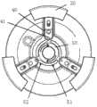
图2是实施例的俯视图;Fig. 2 is the top view of embodiment;
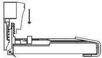
图3是实施例的局部剖切示意图;Fig. 3 is a partially cutaway schematic diagram of an embodiment;
图4是实施例的旋钮盖旋转至第二位置的示意图;Fig. 4 is a schematic diagram of the embodiment of the knob cover rotated to the second position;
图5是实施例的旋钮盖旋转至第二位置时,限压阀的状态示意图;Fig. 5 is a schematic diagram of the state of the pressure limiting valve when the knob cover of the embodiment is rotated to the second position;
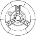
图6是实施例的旋钮盖旋转至第二位置的示意图;Fig. 6 is a schematic diagram of the embodiment of the knob cover rotated to the second position;
图7是实施例的旋钮盖旋转至第三位置时,限压阀的状态示意图;Fig. 7 is a schematic diagram of the state of the pressure limiting valve when the knob cover of the embodiment is rotated to the third position;
图8是实施例的旋钮盖旋转至第四位置的示意图;Fig. 8 is a schematic diagram of the embodiment of the knob cover rotated to the fourth position;
图9是实施例的旋钮盖旋转至第四位置时,限压阀的状态示意图。Fig. 9 is a schematic diagram of the state of the pressure limiting valve when the knob cover of the embodiment is rotated to the fourth position.
图10是实施例的限压阀的阀杆的另外一种设置形式。Fig. 10 is another arrangement form of the valve stem of the pressure limiting valve of the embodiment.
具体实施方式Detailed ways
下面结合附图和实施例对本实用新型作进一步的说明。Below in conjunction with accompanying drawing and embodiment the utility model is described further.
如图1所示,本实施例的压力锅锅盖包括锅盖主体10、扣爪20和用于控制该扣爪20沿锅盖主体10径向移动的控制机构30。该控制机构30包括:外端与该扣爪20固定连接的连接臂40,用于驱动该连接臂40沿锅盖主体10径向移动的转盘50,以及用于驱动该转盘50转动的旋钮机构。As shown in FIG. 1 , the lid of the pressure cooker in this embodiment includes a
如图3所示,该旋钮机构包括旋钮盖61和限压阀62,该限压阀62的阀杆621顶设在该旋钮盖61的下部,该旋钮盖61带动转盘50转动并驱动该阀杆621沿轴向移动以调整该限压阀62的工作压力。该限压阀62包括穿设于锅盖主体10中的阀体622,该阀体622设有用于容置该阀杆621的阀腔,阀杆621的下部设有与该阀腔底部的阀口配合的密封部623,该阀体622中还设有阀杆复位弹簧624,该复位弹簧624上端顶在旋钮盖的推杆部611上,且旋钮盖61与该阀体螺纹连接。As shown in Figure 3, the knob mechanism includes a
如图2所示,该转盘50上设有滑槽,该滑槽包括与锅盖主体10同心的圆弧段51和有径向位移的第二弧段52,连接臂40的内端设有与该滑槽配合的凸柱41。第二弧段52的初始端与锅盖主体10中心的径向距离大于其结束端与锅盖主体10中心的径向距离,且第二弧段52的结束端与圆弧段51的初始端连接。As shown in Figure 2, a chute is provided on the
本实施例的工作原理为:当用户转动旋钮盖61时,旋钮盖61向下运动时,扣爪20和限压阀62机构的状态也随之发生变化。具体变化情况如下。The working principle of this embodiment is: when the user turns the
(1)旋钮盖位于初始位置。如图2、图3所示,用户转动旋钮盖61之前,凸柱41位于第二弧段52初始端,扣爪20与锅盖主体10中心的距离最远,处于开启锅盖的位置;(1) The knob cover is at the initial position. As shown in Figures 2 and 3, before the user turns the
(2)旋钮盖旋转至第二位置。随着用户进一步转动旋钮盖61,如图4、图5所示,凸柱41将移动至第二弧段52的结束端,此时扣爪20与锅盖主体10中心的距离最近,处于关闭锅盖位置;(2) Rotate the knob cover to the second position. As the user further turns the
(3)旋钮盖进一步转动,旋钮盖旋转经过第三位置(见图6、图7),并最终到达第四位置(见图8、图9)。如图6至图9所示,凸柱41进入圆弧段51后,扣爪20与锅盖主体10中心的距离保持不变,仍然处于关闭锅盖的位置。但是随着旋转盖驱动转盘50继续转动,凸柱41将从圆弧段51的初始端向结束端移动,在此过程中,限压阀62中的阀杆621逐渐关闭阀口,也就是说压力锅内的压力阀值逐渐提高。(3) The knob cover is further rotated, and the knob cover rotates through the third position (see Figure 6, Figure 7), and finally reaches the fourth position (see Figure 8, Figure 9). As shown in FIGS. 6 to 9 , after the
此外,限压阀62中的阀杆621既可以顶在旋钮盖61的下部(如图1、图3所示),也可以穿过旋钮盖61的形式(如图10所示),并将阀杆621的顶部设置成警示颜色,例如红色。当阀杆621凸出旋钮盖61的表面时,既可以看到阀杆621顶部的警示颜色,这样就方便用户识别当前压力锅处于高压状态。In addition, the
Claims (4)
Priority Applications (2)
| Application Number | Priority Date | Filing Date | Title |
|---|---|---|---|
| CN2011202595672UCN202173242U (en) | 2011-07-21 | 2011-07-21 | pressure cooker lid |
| US13/554,639US20130019759A1 (en) | 2011-07-21 | 2012-07-20 | Apparatus and method for a pressure cooker lid |
Applications Claiming Priority (1)
| Application Number | Priority Date | Filing Date | Title |
|---|---|---|---|
| CN2011202595672UCN202173242U (en) | 2011-07-21 | 2011-07-21 | pressure cooker lid |
Publications (1)
| Publication Number | Publication Date |
|---|---|
| CN202173242Utrue CN202173242U (en) | 2012-03-28 |
Family
ID=45863156
Family Applications (1)
| Application Number | Title | Priority Date | Filing Date |
|---|---|---|---|
| CN2011202595672UExpired - Fee RelatedCN202173242U (en) | 2011-07-21 | 2011-07-21 | pressure cooker lid |
Country Status (2)
| Country | Link |
|---|---|
| US (1) | US20130019759A1 (en) |
| CN (1) | CN202173242U (en) |
Cited By (10)
| Publication number | Priority date | Publication date | Assignee | Title |
|---|---|---|---|---|
| CN103330481A (en)* | 2013-06-28 | 2013-10-02 | 浙江永达工贸有限公司 | Rotary type pressure cooker |
| CN103423448A (en)* | 2013-04-23 | 2013-12-04 | 杭州东顺染整机械制造有限公司 | Clamping jaw type locking device for cover door of high pressure vessel |
| JP2014045789A (en)* | 2012-08-29 | 2014-03-17 | Katsufumi Aoyanagi | Pressure cooker |
| CN107174117A (en)* | 2016-03-10 | 2017-09-19 | 佛山市顺德区美的电热电器制造有限公司 | The cover assembly of electric pressure cooking saucepan and electric pressure cooking saucepan |
| CN107432667A (en)* | 2016-05-26 | 2017-12-05 | 佛山市顺德区美的电热电器制造有限公司 | The cover assembly of electric pressure cooking saucepan and electric pressure cooking saucepan |
| CN107625411A (en)* | 2016-07-18 | 2018-01-26 | 佛山市顺德区美的电热电器制造有限公司 | Screw guide plate, pot cover component and pressure cooker |
| CN108245000A (en)* | 2016-12-29 | 2018-07-06 | 浙江绍兴苏泊尔生活电器有限公司 | Electric pressure cooker |
| CN110403454A (en)* | 2018-04-26 | 2019-11-05 | 九阳股份有限公司 | A kind of pressure cooker |
| CN110604469A (en)* | 2019-10-21 | 2019-12-24 | 新兴县先丰不锈钢制品有限公司 | Pressure cooker with one-key control function |
| WO2021088185A1 (en)* | 2019-11-05 | 2021-05-14 | 广东美的白色家电技术创新中心有限公司 | Cooking pot and pot lid thereof |
Families Citing this family (29)
| Publication number | Priority date | Publication date | Assignee | Title |
|---|---|---|---|---|
| CA152106S (en)* | 2013-03-01 | 2014-03-27 | Seb Sa | PRESSURE COOKER |
| US20150136769A1 (en)* | 2013-11-21 | 2015-05-21 | Meyer Intellectual Properties Ltd. | Microwave pressure cooker |
| FR3036934B1 (en)* | 2015-06-02 | 2017-07-14 | Seb Sa | AUTOCUIZER HAVING A MANUAL LOCK CONTROL MEMBER |
| USD895346S1 (en)* | 2017-01-25 | 2020-09-08 | Tsann Kuen (Zhangzhou) Enterprise Co., Ltd. | Grill |
| KR101985479B1 (en)* | 2017-07-10 | 2019-09-03 | 쿠쿠전자 주식회사 | electric cooker |
| WO2019032876A1 (en) | 2017-08-09 | 2019-02-14 | Sharkninja Operating Llc | Cooking device and components thereof |
| KR102297855B1 (en)* | 2017-09-07 | 2021-09-03 | 쿠쿠전자 주식회사 | electric cooker |
| CA3079009C (en)* | 2017-10-13 | 2020-12-08 | National Presto Industries, Inc. | Electric pressure canner with digital control |
| CA180616S (en)* | 2017-11-09 | 2019-02-13 | Foshan Shunde Midea Electrical Heating Appliances Mfg Co Ltd | Electric pressure cooker |
| CN109846345A (en)* | 2017-11-30 | 2019-06-07 | 浙江绍兴苏泊尔生活电器有限公司 | Electric pressure cooking saucepan |
| CA178558S (en)* | 2017-12-08 | 2018-10-01 | Double Insight Inc | Pressure cooker |
| CN109892987B (en)* | 2017-12-12 | 2024-02-27 | 佛山市顺德区美的电热电器制造有限公司 | Pot cover assembly and cooking utensil |
| USD914447S1 (en) | 2018-06-19 | 2021-03-30 | Sharkninja Operating Llc | Air diffuser |
| USD883015S1 (en) | 2018-08-09 | 2020-05-05 | Sharkninja Operating Llc | Food preparation device and parts thereof |
| USD903413S1 (en) | 2018-08-09 | 2020-12-01 | Sharkninja Operating Llc | Cooking basket |
| USD883014S1 (en) | 2018-08-09 | 2020-05-05 | Sharkninja Operating Llc | Food preparation device |
| USD934027S1 (en) | 2018-08-09 | 2021-10-26 | Sharkninja Operating Llc | Reversible cooking rack |
| USD876153S1 (en)* | 2018-10-11 | 2020-02-25 | Hy Cite Enterprises, Llc | Pressure cooker |
| WO2020176477A1 (en) | 2019-02-25 | 2020-09-03 | Sharkninja Operating Llc | Cooking system with guard |
| US11051654B2 (en) | 2019-02-25 | 2021-07-06 | Sharkninja Operating Llc | Cooking device and components thereof |
| USD982375S1 (en) | 2019-06-06 | 2023-04-04 | Sharkninja Operating Llc | Food preparation device |
| USD918654S1 (en) | 2019-06-06 | 2021-05-11 | Sharkninja Operating Llc | Grill plate |
| USD899178S1 (en)* | 2019-12-19 | 2020-10-20 | Xiushan Ye | Electric pressure cooker |
| US11678765B2 (en) | 2020-03-30 | 2023-06-20 | Sharkninja Operating Llc | Cooking device and components thereof |
| USD955802S1 (en)* | 2020-04-30 | 2022-06-28 | Beijing Xiaomi Mobile Software Co., Ltd. | Electric pressure cooker |
| CA200996S (en)* | 2020-07-16 | 2021-11-24 | Midea Group Co Ltd | Pot lid |
| USD977898S1 (en)* | 2020-07-16 | 2023-02-14 | Midea Group Co., Ltd. | Multifunctional cooking pot |
| USD935275S1 (en)* | 2021-03-09 | 2021-11-09 | Xiushan Ye | Blender container |
| CN115429105A (en)* | 2022-10-21 | 2022-12-06 | 杭州荣灿科技有限公司 | Clamp mechanism and pot cover and vacuum pressure cooker with same |
Family Cites Families (6)
| Publication number | Priority date | Publication date | Assignee | Title |
|---|---|---|---|---|
| DE3016504A1 (en)* | 1980-04-29 | 1981-11-19 | Württembergische Metallwarenfabrik AG, 7340 Geislingen | VALVE ARRANGEMENT FOR A STEAM PRESSURE COOKER |
| FR2722077B1 (en)* | 1994-07-06 | 1996-08-23 | Seb Sa | JAW LOCKING / UNLOCKING DEVICE OF A LID ON A TANK |
| US6019029A (en)* | 1999-09-09 | 2000-02-01 | Chiaphua Industries Limited | Pressure cooker |
| TW429766U (en)* | 2000-05-22 | 2001-04-11 | Chen Jin Tsai | Improved pressure pot |
| FR2836807B1 (en)* | 2002-03-08 | 2004-07-16 | Seb Sa | PRESSURIZED FOOD COOKING APPLIANCE WITH ROTARY LOCK / RELEASE CONTROL DEVICE |
| FR2862855B1 (en)* | 2003-11-27 | 2006-09-15 | Seb Sa | UNIQUE CONTROL UNIT PRESSURE COOKING APPARATUS FOR DECOMPRESSION AND LOCKING / UNLOCKING |
- 2011
- 2011-07-21CNCN2011202595672Upatent/CN202173242U/ennot_activeExpired - Fee Related
- 2012
- 2012-07-20USUS13/554,639patent/US20130019759A1/ennot_activeAbandoned
Cited By (14)
| Publication number | Priority date | Publication date | Assignee | Title |
|---|---|---|---|---|
| JP2014045789A (en)* | 2012-08-29 | 2014-03-17 | Katsufumi Aoyanagi | Pressure cooker |
| CN103423448A (en)* | 2013-04-23 | 2013-12-04 | 杭州东顺染整机械制造有限公司 | Clamping jaw type locking device for cover door of high pressure vessel |
| CN103423448B (en)* | 2013-04-23 | 2016-07-06 | 杭州东顺染整机械制造有限公司 | Jack catchs type high-pressure bottle lid door locking device |
| CN103330481A (en)* | 2013-06-28 | 2013-10-02 | 浙江永达工贸有限公司 | Rotary type pressure cooker |
| CN107174117B (en)* | 2016-03-10 | 2019-03-12 | 佛山市顺德区美的电热电器制造有限公司 | The cover assembly of electric pressure cooking saucepan and electric pressure cooking saucepan |
| CN107174117A (en)* | 2016-03-10 | 2017-09-19 | 佛山市顺德区美的电热电器制造有限公司 | The cover assembly of electric pressure cooking saucepan and electric pressure cooking saucepan |
| CN107432667A (en)* | 2016-05-26 | 2017-12-05 | 佛山市顺德区美的电热电器制造有限公司 | The cover assembly of electric pressure cooking saucepan and electric pressure cooking saucepan |
| CN107625411A (en)* | 2016-07-18 | 2018-01-26 | 佛山市顺德区美的电热电器制造有限公司 | Screw guide plate, pot cover component and pressure cooker |
| CN108245000A (en)* | 2016-12-29 | 2018-07-06 | 浙江绍兴苏泊尔生活电器有限公司 | Electric pressure cooker |
| CN108245000B (en)* | 2016-12-29 | 2024-01-19 | 浙江绍兴苏泊尔生活电器有限公司 | Electric pressure cooker |
| CN110403454A (en)* | 2018-04-26 | 2019-11-05 | 九阳股份有限公司 | A kind of pressure cooker |
| CN110604469A (en)* | 2019-10-21 | 2019-12-24 | 新兴县先丰不锈钢制品有限公司 | Pressure cooker with one-key control function |
| CN110604469B (en)* | 2019-10-21 | 2024-02-20 | 新兴县先丰不锈钢制品有限公司 | Pressure cooker with one-key control function |
| WO2021088185A1 (en)* | 2019-11-05 | 2021-05-14 | 广东美的白色家电技术创新中心有限公司 | Cooking pot and pot lid thereof |
Also Published As
| Publication number | Publication date |
|---|---|
| US20130019759A1 (en) | 2013-01-24 |
Similar Documents
| Publication | Publication Date | Title |
|---|---|---|
| CN202173242U (en) | pressure cooker lid | |
| US20150090812A1 (en) | Pilot valve switch mechanism and a combined shower applied with the pilot valve switch mechanism | |
| CN102359640B (en) | Special motor valve for intelligent gas meter control | |
| WO2008011768A1 (en) | A cover opening and closing mechanism for pressure cooker | |
| CN103075539B (en) | Single-handle dual-control constant-temperature valve core | |
| WO2016019687A1 (en) | Press type switching valve | |
| CN106870772A (en) | a plug valve | |
| CN204239790U (en) | A kind of fuel gas plug valve | |
| WO2007094884A3 (en) | Dual chamber orifice fitting isolation valve | |
| CN201013965Y (en) | Rocker faucet spool | |
| EP3163400B1 (en) | A double-handle coaxial temperature control valve spool | |
| CN109519562A (en) | A kind of intelligent reversing valve | |
| CN109027269A (en) | A kind of butterfly valve for facilitating coutroi velocity and capable of showing flow velocity | |
| CN209041617U (en) | Piston type diverter valve spool | |
| CN104957972A (en) | Pressure cooker opening and closing structure | |
| CN105240559B (en) | A kind of fuel gas plug valve with cam limit mechanism | |
| CN114942578A (en) | Watch equipped with a locking device for locking an external control unit | |
| CN103128015B (en) | Waterway adjusting switching mechanism and sprinkler | |
| CN205446885U (en) | Pneumatic adjusting butterfly valve | |
| CN204164477U (en) | Seal ring moves around and controls the gas sampling bag valve of side direction air nozzle | |
| CN207378166U (en) | Aqueduct self-control water-saving tap | |
| CN209444883U (en) | A kind of manual operating device of valve | |
| CN109404555A (en) | Gas furnace plug valve | |
| CN207394021U (en) | Valve rod type thermostatic valve core | |
| CN207297892U (en) | A kind of waterway controlling valve core |
Legal Events
| Date | Code | Title | Description |
|---|---|---|---|
| C14 | Grant of patent or utility model | ||
| GR01 | Patent grant | ||
| CF01 | Termination of patent right due to non-payment of annual fee | Granted publication date:20120328 Termination date:20150721 | |
| EXPY | Termination of patent right or utility model |