CN202166897U - Mechanism, pedestal and linkage device for tracking the sun - Google Patents
Mechanism, pedestal and linkage device for tracking the sunDownload PDFInfo
- Publication number
- CN202166897U CN202166897UCN2010205932705UCN201020593270UCN202166897UCN 202166897 UCN202166897 UCN 202166897UCN 2010205932705 UCN2010205932705 UCN 2010205932705UCN 201020593270 UCN201020593270 UCN 201020593270UCN 202166897 UCN202166897 UCN 202166897U
- Authority
- CN
- China
- Prior art keywords
- rods
- row
- column
- sun
- push
- Prior art date
- Legal status (The legal status is an assumption and is not a legal conclusion. Google has not performed a legal analysis and makes no representation as to the accuracy of the status listed.)
- Expired - Fee Related
Links
- 230000007246mechanismEffects0.000titleclaimsabstractdescription81
- NJPPVKZQTLUDBO-UHFFFAOYSA-NnovaluronChemical compoundC1=C(Cl)C(OC(F)(F)C(OC(F)(F)F)F)=CC=C1NC(=O)NC(=O)C1=C(F)C=CC=C1FNJPPVKZQTLUDBO-UHFFFAOYSA-N0.000titleclaimsdescription34
- 230000033001locomotionEffects0.000claimsdescription34
- 238000009434installationMethods0.000claimsdescription17
- 125000006850spacer groupChemical group0.000claimsdescription9
- 230000005484gravityEffects0.000claimsdescription4
- 238000010248power generationMethods0.000abstractdescription7
- 210000003850cellular structureAnatomy0.000abstract1
- 238000010586diagramMethods0.000description57
- 238000000034methodMethods0.000description38
- 230000008859changeEffects0.000description16
- 230000005540biological transmissionEffects0.000description12
- 239000000463materialSubstances0.000description9
- 230000000694effectsEffects0.000description5
- 239000004575stoneSubstances0.000description5
- 239000012141concentrateSubstances0.000description4
- 230000006870functionEffects0.000description4
- 230000008569processEffects0.000description3
- 239000002689soilSubstances0.000description3
- 229910000831SteelInorganic materials0.000description2
- 230000009471actionEffects0.000description2
- 238000003491arrayMethods0.000description2
- 230000008602contractionEffects0.000description2
- 239000012467final productSubstances0.000description2
- 238000010438heat treatmentMethods0.000description2
- 238000004519manufacturing processMethods0.000description2
- 239000010959steelSubstances0.000description2
- 238000004364calculation methodMethods0.000description1
- 230000000739chaotic effectEffects0.000description1
- 230000006835compressionEffects0.000description1
- 238000007906compressionMethods0.000description1
- 238000001816coolingMethods0.000description1
- 239000006185dispersionSubstances0.000description1
- 238000005516engineering processMethods0.000description1
- 230000007613environmental effectEffects0.000description1
- 230000002452interceptive effectEffects0.000description1
- 238000010422paintingMethods0.000description1
- 230000009467reductionEffects0.000description1
- 230000003014reinforcing effectEffects0.000description1
- 238000004904shorteningMethods0.000description1
- 239000007787solidSubstances0.000description1
- 239000000758substrateSubstances0.000description1
- 230000008719thickeningEffects0.000description1
Images


Classifications
- Y—GENERAL TAGGING OF NEW TECHNOLOGICAL DEVELOPMENTS; GENERAL TAGGING OF CROSS-SECTIONAL TECHNOLOGIES SPANNING OVER SEVERAL SECTIONS OF THE IPC; TECHNICAL SUBJECTS COVERED BY FORMER USPC CROSS-REFERENCE ART COLLECTIONS [XRACs] AND DIGESTS
- Y02—TECHNOLOGIES OR APPLICATIONS FOR MITIGATION OR ADAPTATION AGAINST CLIMATE CHANGE
- Y02E—REDUCTION OF GREENHOUSE GAS [GHG] EMISSIONS, RELATED TO ENERGY GENERATION, TRANSMISSION OR DISTRIBUTION
- Y02E10/00—Energy generation through renewable energy sources
- Y02E10/40—Solar thermal energy, e.g. solar towers
- Y02E10/47—Mountings or tracking
- Y—GENERAL TAGGING OF NEW TECHNOLOGICAL DEVELOPMENTS; GENERAL TAGGING OF CROSS-SECTIONAL TECHNOLOGIES SPANNING OVER SEVERAL SECTIONS OF THE IPC; TECHNICAL SUBJECTS COVERED BY FORMER USPC CROSS-REFERENCE ART COLLECTIONS [XRACs] AND DIGESTS
- Y02—TECHNOLOGIES OR APPLICATIONS FOR MITIGATION OR ADAPTATION AGAINST CLIMATE CHANGE
- Y02E—REDUCTION OF GREENHOUSE GAS [GHG] EMISSIONS, RELATED TO ENERGY GENERATION, TRANSMISSION OR DISTRIBUTION
- Y02E10/00—Energy generation through renewable energy sources
- Y02E10/50—Photovoltaic [PV] energy
Landscapes
- Photovoltaic Devices (AREA)
Abstract
Translated fromChinese
Description
Translated fromChinese技术领域technical field
本实用新型是跟踪太阳的机构及基架和联动装置,属于太阳能利用技术领域。 The utility model relates to a mechanism for tracking the sun, a base frame and a linkage device, and belongs to the technical field of solar energy utilization. the
背景技术Background technique
用低造价,简单的方法对太阳跟踪及聚光对太阳能利用来说至关重要,为此国内外许多人提出了许多种跟踪太阳的方法和机构,这些技术可归结为以下五大类: Low cost and simple methods are very important for solar tracking and light concentration. For this reason, many people at home and abroad have proposed many methods and mechanisms for tracking the sun. These technologies can be classified into the following five categories:
一是用一套控制和传动系统控制一个太阳能接收器,这种方法最简单,但造价很贵; One is to use a set of control and transmission system to control a solar receiver, this method is the simplest, but the cost is very expensive;
二是用一套控制和传动系统控制多个柱面聚光镜聚光,是一种单轴跟踪聚光,此方法聚光区为一条焦线区,不能产生高温,造价中等; The second is to use a set of control and transmission system to control multiple cylindrical condensers to concentrate light, which is a single-axis tracking and focusing. The focusing area of this method is a focal line area, which cannot generate high temperature, and the cost is medium;
三是用一套控制和传动系统控制多个聚光镜分散聚光,聚光镜总面积在数十平方米左右,这种多焦点的分散聚光应用成本高,总造价也较高; The third is to use a set of control and transmission system to control multiple condensers to disperse and concentrate the light. The total area of the condensers is about tens of square meters. This kind of multi-focus dispersed light application is costly and the total cost is also high;
四是用多套控制和传动系统控制多个聚光镜将太阳光聚焦到塔上一点,如塔式聚光和盘式聚光。这种方法可得到高聚光度,但造价很高; The fourth is to use multiple sets of control and transmission systems to control multiple concentrating mirrors to focus the sunlight on a point on the tower, such as tower concentrating and disc concentrating. This method can get high concentration, but the cost is very high;
五是用一套控制和传动系统控制多个接收器或聚光镜,分散或集中聚光,聚光面积可达数十至数千平方米,甚至更大面积,用这种方法成本最低,有许多人提出了许多方案,如: The fifth is to use a set of control and transmission system to control multiple receivers or condensers to disperse or concentrate the light. The concentrating area can reach tens to thousands of square meters, or even a larger area. This method has the lowest cost. There are many Many proposals have been proposed, such as:
中国专利CN1361397提出了一种由柱面聚光镜、导轨框架、传动和控制装置组成的聚光装置,由一套控制和传动系统控制多个聚光镜聚光,但这种聚光方式为单轴聚光,聚光度低,光、热损耗较多,造价中等。 Chinese patent CN1361397 proposes a concentrating device consisting of cylindrical concentrating mirrors, rail frames, transmission and control devices. A set of control and transmission systems control multiple concentrating mirrors for concentrating light, but this concentrating method is single-axis concentrating , low light concentration, more light and heat loss, and medium cost. the
中国专利CN101098113提到一种平面网架二维跟踪太阳的光伏发电装置,其方法是:多个光伏发电器一同装在倾斜面摇动支架的平面网架上,用驱动平面转动支架和垂直面转动支架的方法跟踪太阳,这种方法体积庞大,抗风压能力差,造价很高。 Chinese patent CN101098113 mentions a photovoltaic power generation device for two-dimensional tracking of the sun with a planar network frame. The method of support tracks the sun, and this method is bulky, and wind pressure resistance is poor, and cost is very high. the
中国专利CN101504199提出了一种用一套控制和驱动系统驱动一个由多个太阳能接收器或反射镜组成的阵列的方案,但说明书中只提出了这种功能设想,实际方案无法实现其功能设想,如其在图1中提出了一个基本的驱动原理图实际上是不可能实现其功能设想的,因为按其图1根本不可能实现有效的转动,连一个方向的有效转动也不可能,在其后提出的方案中没有标明整个阵列如何与地面连结,其如何有效驱动无法看出来,另外在其后的方案中提出用螺杆连杆机构驱动,这样会造成靠近螺杆机构的接收器(或反光板)与远离螺杆机构的接收器或反光板的转动角度不一样,且差距很大,无法有效接收或聚光。 Chinese patent CN101504199 proposes a scheme of driving an array composed of multiple solar receivers or reflectors with a set of control and drive system, but this functional assumption is only proposed in the specification, and the actual scheme cannot realize its functional assumption. As it proposes a basic driving principle diagram in Fig. 1, it is actually impossible to realize its function assumption, because it is impossible to realize effective rotation according to Fig. 1, and even effective rotation in one direction is impossible. The proposed scheme does not indicate how the entire array is connected to the ground, and how it is effectively driven cannot be seen. In addition, in the subsequent scheme, it is proposed to use a screw linkage mechanism to drive, which will cause the receiver (or reflector) close to the screw mechanism The rotation angle of the receiver or reflector far away from the screw mechanism is not the same, and the gap is very large, which cannot effectively receive or gather light. the
中国专利200810007285.6(申请号)和中国专利200810182738.9(申请号),两者都提出了一种用一套控制和驱动系统驱动一个由多个太阳能接收器或反射镜组成的阵列的方案,其 中提出了多种方案,这些方案中有如下严重问题,无法有效实现其提出的功能: Chinese Patent 200810007285.6 (Application No.) and Chinese Patent 200810182738.9 (Application No.), both of which propose a scheme to drive an array composed of multiple solar receivers or reflectors with a set of control and drive systems, which propose A variety of schemes have been proposed, and these schemes have the following serious problems, which cannot effectively realize the functions proposed by them:
一是方案中的多套方案都没有标明整个阵列如何与地面连结,以及行列如何互动,不知其如何有效驱动; One is that many sets of plans in the plan do not indicate how the entire array is connected to the ground, and how the rows and columns interact, and how to effectively drive it is not known;
二是方案中提出用螺杆连杆机构驱动,这样会造成靠近螺杆机构的接收器或反射镜与远离螺杆机构的接收器或反射镜的转动角度不一样,且差距很大,无法有效接收或聚光; The second is that the scheme proposes to use a screw linkage mechanism to drive, which will cause the receiver or reflector close to the screw mechanism to have a different rotation angle from the receiver or reflector far away from the screw mechanism, and the gap is very large, which cannot effectively receive or focus Light;
三是行驱动对列驱动相互间造成影响,其实际聚光效果不仅不是空间中的点聚光,就连线聚光都谈不上,而是一个很大的平面,原因是,行列相互影响,每块反射镜的上、下、左、右、前、后方向均有很大差异,每一行和每一列的连杆实际运行后都不在一个平面上,行、列连杆互相扭曲,既不能跟踪太阳,更不可能将太阳光聚焦到空间某点状区域; The third is that the row drive has an influence on the column drive. The actual concentrating effect is not only a point concentrating in space, not even a line concentrating, but a large plane. The reason is that the rows and columns affect each other. , the up, down, left, right, front and rear directions of each reflector are very different, the connecting rods of each row and column are not on the same plane after actual operation, and the connecting rods of the rows and columns are twisted each other, both It is impossible to track the sun, and it is impossible to focus the sunlight to a certain point-like area in space;
四是专利说明书中没有说明行驱动和列驱动放在什么位置,按说明书的叙述理解应该两者放在一起或相互间很近距离,或至少在同一方向或同一边沿上,这样会造成阵列的驱动不对称,特别在有风压时和大的偏转角时,由于装置的自重等会引起装置的非对称扭转,造成各聚光反射镜的方向混乱; Fourth, the patent specification does not specify where the row driver and the column driver should be placed. According to the description in the specification, it should be understood that the two should be placed together or at a very close distance from each other, or at least in the same direction or on the same edge, which will cause the array. The drive is asymmetrical, especially when there is wind pressure and a large deflection angle, due to the self-weight of the device, the asymmetrical twist of the device will be caused, causing the direction of each concentrating mirror to be confused;
五是其中之一方案提到用连杆控制行(或列)跟踪,扭动控制列(或行)跟踪,方案中仅用功能性语言描述了要达到的目的,而没有具体的实施方案和结构,即便如此,这一方案的功能实际上跟早已申请的美国专利US6302099几乎一样,其缺点如下述美国专利一样,不再叙述; The fifth is that one of the schemes mentions the use of connecting rods to control row (or column) tracking, and twisting to control column (or row) tracking. In the scheme, only functional language is used to describe the purpose to be achieved, without specific implementation plan and Even so, the function of this scheme is almost the same as the already applied US patent US6302099, and its shortcomings are the same as the following US patents, which will not be described again;
六是上述专利中提到用角平分线方法补偿达不到真正跟踪聚焦的目的; Sixth, it is mentioned in the above-mentioned patent that compensation by the angle bisector method cannot achieve the purpose of true tracking and focusing;
七是没有考虑温度和应力伸缩的影响,实际上对一个大的阵列来说,温度和应力引起的装置的尺寸的伸长和缩短影响非常大,会产生较大的跟踪精度偏差; Seventh, the influence of temperature and stress stretching is not considered. In fact, for a large array, the elongation and shortening of the size of the device caused by temperature and stress have a very large impact, which will produce a large tracking accuracy deviation;
美国专利US6058930提出一种用一个扭转管支撑一排呈水平的矩形的太阳接收面板,扭转管被安放在固定于地面的支柱上,用扭转管的转动使太阳接收面板正对太阳,用连杆机构连接多排这样的扭转管。这种方法的缺点是:一是只能用于一维驱动,二是风压和接收器自重引起扭转力矩使扭转管发生变形,从而影响接收面板的接收角度,三是连杆机构在本身长度较长的情况下会由于环境温度的变化而使得长度发生较大变化,从而使得其驱动扭转管产生较大的角度误差,四是这种方法不能够将太阳光聚焦到一个接收器上。 U.S. Patent US6058930 proposes a row of horizontal rectangular sun receiving panels supported by a twisted tube. Mechanisms connect multiple rows of such torsion tubes. The disadvantages of this method are: first, it can only be used for one-dimensional driving; second, the torsion torque caused by the wind pressure and the receiver's own weight deforms the torsion tube, thereby affecting the receiving angle of the receiving panel; In the long case, the length will change greatly due to the change of the ambient temperature, so that the driving torsion tube will produce a large angle error. Fourth, this method cannot focus the sunlight on a receiver. the
美国专利US6302099提出了一种用一可转动的脊柱支撑在一固定在地面的支柱上,在脊柱上再安放一垂直的旋转轴,在垂直旋转轴上安放太阳收集器,可转动的脊柱和垂直的旋转轴分别由滑轮和缆线连接到一驱动装置上用以提供南北、东西方向的对太阳的角度跟踪,若干个这样的机构组成一个阵列,用一个控制系统和两个驱动系统驱动多个太阳接收器。这种 方法有三个很大的缺点:一是这种驱动方式由于太阳接收器的自重及有风时会造成连接太阳接收器的杆(或棒)产生扭转,多个太阳接收器共同作用于脊柱,使脊柱发生扭转,当太阳接收器数量较多时,脊柱会发生较大的扭转角,且每个太阳接收器附近的脊柱的扭转角不一样,从而使各接收器的接收方向发生改变,不能正常接收太阳光,二是由于环境温度是变化的,温度变化使传动缆线的长度发生变化,从而使得各接收器的传动角度不一致,而产生系统误差,三是当太阳接收器面积较大,重量较重时,传动缆线与滑轮之间的摩擦力不足以驱动滑轮运动,很容易发生滑动,从而使得各接收器的传动角度发生混乱,四是由于自重及风压造成的缆线的拉应力伸长,从而使传动角度发生偏差。 U.S. Patent No. 6,302,099 proposes a rotatable spine supported on a pillar fixed on the ground, and a vertical rotation axis is placed on the spine, and a solar collector is placed on the vertical rotation axis. The rotatable spine and vertical The rotating shafts are respectively connected to a driving device by pulleys and cables to provide angular tracking of the sun in the north-south and east-west directions. Several such mechanisms form an array, and one control system and two drive systems drive multiple sun receiver. This method has three major disadvantages: First, this driving method will cause the rod (or rod) connected to the sun receiver to twist due to the self-weight of the sun receiver and when there is wind, and multiple sun receivers act together on the spine. , so that the spine is twisted. When the number of solar receivers is large, the spine will have a larger twist angle, and the twist angle of the spine near each sun receiver is different, so that the receiving direction of each receiver changes, which cannot To receive sunlight normally, the second is that the ambient temperature changes, and the length of the transmission cable changes due to temperature changes, so that the transmission angles of each receiver are inconsistent, resulting in system errors. The third is that when the sun receiver has a large area, When the weight is heavy, the friction between the transmission cable and the pulley is not enough to drive the pulley, and it is easy to slip, which makes the transmission angle of each receiver chaotic. Fourth, the cable is pulled due to its own weight and wind pressure. The stress elongates, thereby causing the transmission angle to deviate. the
实用新型内容Utility model content
本实用新型的目的是:为克服现有技术中的对太阳光跟踪精度差、各接收器跟踪精度不一致、误差很大、框架阵列装置在风压、自重及温度等影响下易变形、不能有效跟踪太阳,加工误差,安装精度等累积误差较大,造价高等缺点,提供一种结构简洁、造价便宜、具有良好环境适应能力,即能克服风压、温差、重力及加工误差、安装精度等影响,使框架阵列中各太阳光接收装置均有较高跟踪精度的大型的跟踪太阳的框架阵列机构,用于中、大型及超大型的太阳能利用系统,包括分散应用和集中应用系统。 The purpose of the utility model is: to overcome the poor tracking accuracy of the sunlight in the prior art, the tracking accuracy of each receiver is inconsistent, the error is large, and the frame array device is easily deformed under the influence of wind pressure, self-weight and temperature, and cannot be effective. Tracking the sun, processing error, installation accuracy and other accumulated errors are relatively large, and the cost is high. Provide a simple structure, low cost, and good environmental adaptability, that is, it can overcome the influence of wind pressure, temperature difference, gravity, processing error, and installation accuracy. , so that each solar light receiving device in the frame array has a large-scale sun-tracking frame array mechanism with high tracking accuracy, which is used for medium, large and super large solar energy utilization systems, including decentralized applications and centralized application systems. the
为了实现上述目的,本实用新型的技术方案是:一种跟踪太阳的机构和基架及联动装置,包括太阳光跟踪接收模块阵列及其支撑框架、驱动模块阵列对准太阳的方位角和高度角的驱动机构、控制方位角和高度角驱动机构的跟踪控制电路、向跟踪控制电路传送信号的太阳光方位角和高度角传感器;其技术特征是:若干根杆平行排列成一行,相互间隔一距离,这一距离可以都是等距离,也可以不是等距离,这一行杆可以位于一个平面内,也可以不在一个平面内,但是为了结构简便,间隔距离最好做成等距离,若干根杆也最好位于一个平面内,杆的两端头中至少一个端头或靠近端头处相互连结;另有若干根杆也相互间隔一距离平行排列成一列,与上述的一行杆一样,为了结构简便,这一列杆最好是等间距及最好位于一个平面内,杆的两端头中至少一个端头或靠近端头处相互连结;上述的杆包括管、棒、角钢、工字钢、槽钢等各种形状的类似杆状的结构,包括各种材料做成的;排成一行的若干根杆至少一个端头或靠近端头处相互连结成为一个整体再通过一轴或类似轴的构件连结到驱动机构上;排成一列的若干根杆也至少一个端头或靠近端头处相互连结成为一个整体再通过一轴或类似轴的构件连结到另一边的驱动机构上;上述的端头是指同一端的端头。可用若干根加强筋连结上述轴和框架阵列。 In order to achieve the above object, the technical solution of the utility model is: a mechanism for tracking the sun, a pedestal and a linkage device, including the solar tracking receiving module array and its supporting frame, and the azimuth and altitude angles of the driving module array aligned with the sun The driving mechanism, the tracking control circuit controlling the azimuth and altitude driving mechanism, the sunlight azimuth and altitude sensor that transmits signals to the tracking control circuit; its technical characteristics are: a number of rods are arranged in parallel in a row, with a distance from each other , this distance may or may not be equidistant, this row of rods may be located in one plane, or may not be in one plane, but in order to simplify the structure, it is best to make the distances equidistant, several rods also Preferably located in a plane, at least one of the two ends of the rods is connected to each other at or near the ends; there are also several rods arranged in parallel at a distance from each other, which is the same as the above-mentioned row of rods, for the sake of simple structure , this row of rods is preferably equidistant and preferably located in a plane, and at least one of the ends of the rods is connected to each other at or near the ends; the above-mentioned rods include pipes, rods, angle steel, I-beam, grooves Rod-like structures of various shapes such as steel, including those made of various materials; several rods arranged in a row are connected to each other at least at one end or near the end to form a whole, and then pass through a shaft or a member similar to a shaft Linked to the driving mechanism; several rods arranged in a row are also connected to each other at least at one end or near the end to form a whole, and then connected to the driving mechanism on the other side through a shaft or a member similar to the shaft; the above-mentioned end Refers to the ends of the same end. A plurality of reinforcing ribs can be used to connect the above-mentioned shaft and the frame array. the
排成一行的若干根杆和另一列的若干根杆成某一角度上、下放置或交叉放置、或放置于 同一平面并分别通过铰链连结到若干根立柱上,比如N×M根立柱上,或两排杆分别两两相互铰链后,其中之一排杆再分别与若干根立柱,比如N×M根立柱铰链;上述两排杆也可不直接与立柱铰链,可将两排杆两两分别相互铰链后,再与位于立柱上端或中间处的太阳光接收装置通过某种方式铰链,比如将两排杆直接与太阳接收装置的边沿上某点铰链、或与固定连接在太阳接收装置上的摇杆铰链、或者将一排杆与太阳接收装置铰链,而另一排杆与固定连接在太阳接收装置上的摇杆铰链,或者反之,或用其他铰链方式。 A number of rods in a row and a number of rods in another row are placed up, down or crossed at a certain angle, or placed on the same plane and connected to several columns through hinges, such as N×M columns, Or after the two rows of rods are hinged to each other in pairs, one of the rows of rods is hinged with several uprights, such as N×M uprights; After being hinged to each other, they are hinged in some way with the solar receiving device located at the upper end or in the middle of the column, for example, the two rows of rods are directly hinged to a certain point on the edge of the solar receiving device, or are fixedly connected to the solar receiving device. Rocker hinges, or hinge one row of rods to the sun receiver, and the other row of rods to a rocker that is fixedly connected to the sun receiver, or vice versa, or with other hinges. the
立柱由一段或二段或三段或四段构成,所有立柱可以做成完全一样的,也可以做成不完全一样,但至少一部分立柱须满足如下条件:至少由两段构成、中间有可使立柱绕两个方向的转轴转动的结构件,例如中间某处有一个可在某一立体角内转动的万向节、或中间某两处分别有可绕某一转动轴转向的转向支架、或中间某两处分别有两个不同方向的轴承和转轴、或中间某两处分别有不同转动方向的圆柱副、或其他能使立柱绕两个方向的转轴转动的结构件,这部分的立柱下端固定在可在某些方向自由伸展的基架上或地面上或其他构件上,这部分立柱的下端也可不固定,而改由上端铰链悬挂在由纵向和横向若干根杆成某个角度放置并相互连结组成的支架上,此支架由若干根固定在地面上或基架或其他构件上的支撑柱支撑,剩下的另一部分立柱可做成任意形状和长度,但它们的下端悬空,上端也不与其他支架铰链悬挂,即也处于悬空状态。 The column consists of one section, two sections, three sections or four sections. All the columns can be made exactly the same or not, but at least some of the columns must meet the following conditions: at least two sections, with a A structural member in which the column rotates around two axes of rotation, for example, there is a universal joint that can rotate within a certain solid angle somewhere in the middle, or there are steering brackets that can turn around a certain rotation axis at two places in the middle, or There are two bearings and rotating shafts in different directions in the middle, or there are cylinder pairs in different directions in the middle, or other structural parts that can make the column rotate around the rotating shaft in two directions. The lower end of the column in this part It is fixed on the base frame or on the ground or other components that can be freely extended in certain directions. On a bracket composed of interconnections, the bracket is supported by several support columns fixed on the ground or on the base frame or other components, and the remaining columns can be made into any shape and length, but their lower ends are suspended, and the upper ends are also suspended. It is not hinged with other brackets, that is, it is also in a suspended state. the
立柱上端或中间某位置安装太阳光接收装置如光伏电池组件或热能接收器或反射镜、反射镜与透镜的组合装置或其他太阳光接收装置等,支撑框架阵列包括行杆和列杆及立柱,框架阵列可以为三、四、五等多边形或其他形状。 Install solar light receiving devices such as photovoltaic cell modules or thermal energy receivers or reflectors, combination devices of reflectors and lenses, or other solar light receiving devices on the upper end or at a certain position in the middle of the column. The supporting frame array includes row rods, column rods and columns. The frame array can be three, four, five, etc. polygonal or other shapes. the
驱动器分别位于支撑框架阵列的相邻两边,或其他非对称的两边,单个驱动器的驱动轴线或多个驱动器的驱动合力线处于框架阵列的对称或基本对称位置,以免发生不对称驱动问题。 The drivers are respectively located on adjacent two sides of the supporting frame array, or other asymmetrical sides, and the driving axis of a single driver or the driving resultant line of multiple drivers is located in a symmetrical or substantially symmetrical position of the frame array to avoid asymmetric driving problems. the
上述两边的驱动器分别通过一根或若干根杆或类似杆的结构与行、列框架阵列直接连结或直接铰链,或通过摇杆铰链、或与太阳接收装置直接铰链或通过摇杆铰链,或将若干行和若干列杆直接作为推拉杆而不用另外的杆,用以驱动支撑框架阵列;上述用若干根推拉杆的目的是为了使框架阵列受力更均匀,减少结构形变,当用若干根推拉杆时,可用一能承受大的力量而不发生变形的较宽、较厚的扁状杆将若干根推拉杆连接起来,用一个或若干个驱动器驱动。 The drivers on the above two sides are directly connected or directly hinged to the row and column frame arrays through one or several rods or similar rod structures, or through rocker hinges, or directly hinged with the sun receiving device or through rocker hinges, or Several rows and columns of rods are directly used as push-pull rods without additional rods to drive the supporting frame array; the purpose of using several push-pull rods above is to make the force of the frame array more uniform and reduce structural deformation. When pulling the rods, several push-pull rods can be connected by a wider and thicker flat rod that can withstand a large force without deformation, and driven by one or several drivers. the
上述两边的驱动器中至少有一边的驱动器安装在一维转向支架上或圆柱副上或弧形滑槽内或其他可使驱动器做一维转动的构件上,上述的一维转向支架或圆柱副或弧形滑槽或其他 等构件安装在地面上或安装在固定于地面的其他构件上,至少有一边的驱动器驱动支撑框架运动的同时带动另一边的驱动器运动,并与立柱转动相同或相近的角度,这样可使行、列两个方向的运动协调行动,不会产生角度扭曲问题。 At least one of the drivers on the above two sides is installed on the one-dimensional steering bracket or on the cylindrical pair or in the arc chute or on other components that can make the driver rotate one-dimensionally. The above-mentioned one-dimensional steering bracket or cylindrical pair or The curved chute or other components are installed on the ground or other components fixed on the ground. At least one driver on one side drives the movement of the support frame and drives the driver on the other side to move, and rotates at the same or similar angle as the column , so that the movements in the two directions of row and column can be coordinated without any angle distortion. the
上述两边的驱动器最好分别只用一个,这样可简化结构及减少成本。 It is preferable to use only one driver on the above-mentioned two sides respectively, which can simplify the structure and reduce the cost. the
一边的驱动器驱动排成一排的若干根杆绕某一轴转动,另一个驱动器驱动排成一排的若干根杆绕另一轴转动,这两个轴的夹角可以为任意一个角度,但最好是夹角为90°,即两个轴相互垂直,杆的运动使立柱发生角度变化,从而使位于立柱上端或中间某处的太阳光接收装置的接收角度发生变化,太阳光在任何位置都可以用太阳的高度角和方位角来描述定位,而高度角和方位角可分别分解投影到上述的两个轴上,比如说相互垂直的位于经、纬度方向的轴上,这样即可跟踪太阳光的角度变化。 The driver on one side drives several rods arranged in a row to rotate around a certain axis, and the other driver drives several rods arranged in a row to rotate around another axis. The angle between the two axes can be any angle, but The best angle is 90°, that is, the two axes are perpendicular to each other. The movement of the rod causes the angle of the column to change, so that the receiving angle of the sunlight receiving device located at the upper end of the column or somewhere in the middle changes. The sunlight is at any position Both the altitude and azimuth of the sun can be used to describe the positioning, and the altitude and azimuth can be decomposed and projected onto the above two axes, for example, the axes perpendicular to each other in the longitude and latitude directions, so that it can be tracked The angle of sunlight changes. the
上述框架阵列中的立柱与杆的铰链有多种方式,杆和杆相互间的铰链也有多种方式,在后面的实施例中将分别给出几种方式。 There are many forms of hinges for the uprights and rods in the above-mentioned frame array, and there are also many forms for the hinges between the rods, and several methods will be given in the following embodiments. the
上述驱动器可由光电控制器控制,即根据太阳光入射角不同而输出不同的控制指令,从而控制驱动机构的运动,也可用时钟方法控制,或者用其他方法控制,或者几种方法同时使用;上述驱动器可以是任何一种驱动机构,如涡轮涡杆式、齿轮连杆式、齿轮链条式、飞轮连杆式、液压式、电机减速机构式等等。 The above-mentioned driver can be controlled by a photoelectric controller, that is, different control commands are output according to different incident angles of sunlight, thereby controlling the movement of the driving mechanism, and it can also be controlled by a clock method, or controlled by other methods, or several methods are used simultaneously; the above-mentioned driver It can be any kind of driving mechanism, such as worm gear type, gear connecting rod type, gear chain type, flywheel connecting rod type, hydraulic type, motor reduction mechanism type and so on. the
本实用新型的太阳角度跟踪方式是:首先确定立柱和太阳接收装置的初始位置,使太阳接收装置正对着太阳或者根据其他用途使反射镜或透镜或这两者的组合的太阳光照射到位于框架阵列中央某处或边上某处的接收塔上的接收器上,初始位置的确定可由在工厂生产时确定,也可在安装现场确定;太阳跟踪控制器根据太阳在经度和纬度方向的角度即俗称的方位角和高度角信息发出控制指令,驱动器接收控制器的控制指令,推动或拉动推拉杆运动,推拉杆的运动使行和列杆运动,继而带动立柱运动,使立柱与初始位置发生角度偏移,立柱的角度偏移量视应用的方式不同而不同,若为分散应用即每个接收装置为相对独立的光伏电池组件或热能接收器,则需要太阳接收装置正对着太阳,此时立柱在两个方向的角度偏移量应等于太阳在同样两个方向上的偏移量,这只需调整驱动器驱动推拉杆的运行距离与立柱的角度的偏移的关系即可做到;若为集中应用,比如将太阳接收装置例如反射镜将太阳光反射到接收塔上的接收器上,则此时只需将立柱在两个方向上的角度偏移量等于太阳在同样两个方向的角度偏移量的二分之一,即可使反射镜将太阳光反射到接收塔上的接收器上,这也只需调整驱动器驱动推拉杆的运行距离与立柱的角度偏移的关系即可。 The solar angle tracking method of the present utility model is: first determine the initial positions of the column and the sun receiving device, make the solar receiving device face the sun or make the sunlight of the reflector or the lens or the combination of the two irradiate to the location where the sun is located. On the receiver on the receiving tower somewhere in the center of the frame array or somewhere on the side, the initial position can be determined at the time of factory production or at the installation site; the sun tracking controller is based on the angle of the sun in the direction of longitude and latitude That is, the commonly known azimuth and altitude information sends out control commands. The driver receives the control commands from the controller and pushes or pulls the push-pull rod to move. The movement of the push-pull rod makes the row and column rods move, and then drives the column to move, so that the column is aligned with the initial position. Angle offset, the angle offset of the column varies depending on the application. If it is a decentralized application, that is, each receiving device is a relatively independent photovoltaic cell module or thermal energy receiver, the sun receiving device needs to face the sun. When the angle offset of the column in two directions should be equal to the offset of the sun in the same two directions, this can be done by adjusting the distance between the driving distance of the drive push-pull rod and the offset of the angle of the column; If it is a concentrated application, such as a sun receiving device such as a reflector to reflect sunlight to the receiver on the receiving tower, then only the angular offset of the column in two directions is equal to the sun in the same two directions One-half of the angular offset of the reflector can make the reflector reflect the sunlight to the receiver on the receiving tower, which only needs to adjust the relationship between the driving distance of the drive push-pull rod and the angular offset of the column. Can. the
根据不同的用途和需要,可以通过调整驱动器驱动推拉杆的运行距离与立柱的角度偏移的关系即可满足特定的要求,调整的方法有很多,比如调整驱动器与推拉杆的驱动角度关系及驱动器输出轴或臂的长短,或调整推拉杆与行杆和列杆的位置关系,或调整行杆和列杆与立柱或太阳接收装置的铰链位置等等,在此不再一一叙述。 According to different uses and needs, specific requirements can be met by adjusting the relationship between the driving distance of the driver and the angular offset of the column. There are many adjustment methods, such as adjusting the driving angle relationship between the driver and the push-pull rod and the driver The length of the output shaft or the arm, or the positional relationship between the adjustment push-pull rod and the row rod and column rod, or the hinge position of adjusting the row rod, column rod and column or the sun receiving device, etc., are not described one by one here. the
通过以上设计,即可仅用一套跟踪控制系统和两个一维(单轴)驱动器控制驱动数千至数万平方米面积的太阳光接收器较精确地跟踪太阳。 Through the above design, only one set of tracking control system and two one-dimensional (single-axis) drivers can be used to control and drive the solar receiver with an area of thousands to tens of thousands of square meters to track the sun more accurately. the
在上述驱动器与推拉杆相连结的轴或臂上分别安装有一配重机构和防风调节及刹车装置,配重机构的作用是:用与阵列框架及太阳接收装置重量接近的配重块,通过配重装置使两者在任何角度时均处于力矩平衡状态或基本平衡状态,从而大大减少驱动器的驱动功率,防风调节及刹车装置的目的是当有超出设计的风速负荷时,防风调节及刹车装置将框架阵列中的太阳接收装置调节到与水平面最小的夹角位置,及固定在此位置,以防大风破坏。 A counterweight mechanism and a windproof adjustment and braking device are respectively installed on the shaft or arm where the above-mentioned driver is connected with the push-pull rod. The heavy device makes both of them in the state of torque balance or basic balance at any angle, thereby greatly reducing the driving power of the driver. The solar receivers in the frame array are adjusted to the minimum angle position with the horizontal plane and fixed at this position to prevent damage from strong winds. the
上述框架阵列的尺寸较大时,此时温度的变化将使上述杆件的长度发生相应的变化,此时将对立柱的倾角造成较大影响,为克服这一影响,在本实用新型中设计了一基架,此基架由若干根杆或管按某种方式排列组合连结而成,若干个固定于地面或其他构件上的限位套限制基架的上、下运动在很小范围,或将基架放置于地面再在基架上放上沙袋等有一定重量的物体,基架的相邻两边或非对称的两边分别连结在固定于地面或驱动机构基座上,对三、四边形或类似形状的基架,基架的相邻两边分别连结在一轴上,此轴的另一端连结到驱动机构的基座上或固定在驱动机构附近的地面或用其他方式固定,对其他多边形或类似形状基架相邻两边分别连结在一轴上,此轴的另一端连结到驱动机构的基座上或固定在驱动机构附近的地面或用其他方式固定,另外的两边或多个边可自由伸展,至少一部分立柱的下端固定在基架上,基架材料的选取只需满足膨胀系数与框架阵列中的行杆和列杆及推拉杆这几种杆件材料相同或接近即可,这样当温度发生变化时,框架阵列中的杆件尺寸和基架将一同发生相同或相近的变化,从而克服框架阵列中的杆件伸缩对立柱的倾角影响。 When the size of the above-mentioned frame array is large, the change of temperature at this time will cause the length of the above-mentioned rods to change accordingly, which will have a great impact on the inclination angle of the column. In order to overcome this effect, the utility model designs A pedestal, the pedestal is formed by arranging and combining several rods or tubes in a certain way, and several limit sleeves fixed on the ground or other components limit the up and down movement of the pedestal in a small range, Or place the pedestal on the ground and put sandbags and other objects with a certain weight on the pedestal. The adjacent two sides or asymmetrical two sides of the pedestal are respectively connected and fixed on the ground or the base of the driving mechanism. Or a base frame of similar shape, the adjacent two sides of the base frame are respectively connected to a shaft, and the other end of the shaft is connected to the base of the driving mechanism or fixed on the ground near the driving mechanism or fixed in other ways, for other polygons Or the adjacent two sides of the base frame of similar shape are respectively connected on a shaft, and the other end of the shaft is connected to the base of the driving mechanism or fixed on the ground near the driving mechanism or fixed in other ways, and the other two or more sides can be The lower ends of at least a part of the columns are fixed on the base frame, and the material of the base frame only needs to meet the same or close expansion coefficient as the row rods, column rods and push-pull rods in the frame array. When the temperature changes, the size of the rods in the frame array and the base frame will have the same or similar changes, so as to overcome the influence of the expansion and contraction of the rods in the frame array on the inclination angle of the column. the
上述框架阵列的尺寸较大时,一方面相应的杆件尺寸较长,除上述温度变化引起的杆件尺寸变化外,另一方面框架阵列的自重及所受到的风的压力都将较大,从而对框架阵列的杆件产生较大的拉伸或压缩应力,使杆件发生较大的应力伸缩,此时将如同温度引起的杆件尺寸的变化一样将对立柱的倾角造成较大影响,且对每一立柱的倾角的影响呈梯度分布,除此之外,多个推拉杆与立柱或推拉杆之间铰链时的间隙误差也较大,为克服这些影响,在本实用新型中设计了一个联动机构,它可使当驱动器驱动行列框架阵列运动时牵引基架一起运动。 When the size of the above-mentioned frame array is large, on the one hand, the corresponding bar size is longer. In addition to the change in the bar size caused by the above-mentioned temperature change, on the other hand, the self-weight of the frame array and the pressure of the wind will be larger. As a result, a large tensile or compressive stress is generated on the rods of the frame array, causing a large stress expansion and contraction of the rods. At this time, it will have a great impact on the inclination angle of the column just like the change in the size of the rods caused by temperature. And the influence on the inclination angle of each column is distributed in a gradient. In addition, the gap error between multiple push-pull rods and the hinges between the columns or push-pull rods is also relatively large. In order to overcome these effects, a design is made in the utility model A linkage mechanism that enables the traction base frame to move together when the drive drives the array of row and column frames. the
联动机构的结构和工作原理是:联动机构内部为圆柱形,圆柱形的内径与阵列框架的杆的运动轨迹相同,连结框架阵列的杆伸入联动机构内,连接底部基架的杆与联动机构固定连接,基架的另一端与驱动器的底座相连接或固定在地面上或其他构件上,连接框架阵列的杆在联动机构的圆柱形内表面运动,当温度变化时或应力变化或重力变化时,阵列框架中的杆将会伸缩从而推动或拉动联动机构运动,而联动机构运动将拉伸或压缩基架,使框架阵列杆与基架杆的长度始终相同,联动机构的数量为两个,分布在与驱动器对称的位置,联动机构可以是一个整体也可以是分为两个部分,视驱动器而定,当驱动器为两边的驱动器均安装在一维转向支架上时,联动机构也要相应地都安装在一维转向支架上,且两者转动角度都要一一对应相同;当驱动器为一个安装在一维转向支架上,而另一个固定安装于地面或其他基件上时,联动机构也要相应地一个安装在一维转向支架上,另一个固定安装于地面或其他基件上,并且两者转轴的转动角度都要一一对应相同。联动机构下方可安装若干个滑轮及若干条滑槽,以使联动机构的滑动摩擦阻力较小。 The structure and working principle of the linkage mechanism are: the interior of the linkage mechanism is cylindrical, and the inner diameter of the cylinder is the same as the movement track of the rods of the array frame. Fixed connection, the other end of the pedestal is connected to the base of the driver or fixed on the ground or other components, the rods connecting the frame array move on the cylindrical inner surface of the linkage mechanism, when the temperature changes or the stress changes or the gravity changes , the rods in the array frame will stretch to push or pull the linkage movement, and the linkage movement will stretch or compress the base frame so that the frame array rods are always the same length as the base frame rods, and the number of linkages is two, Distributed at a position symmetrical to the driver, the linkage mechanism can be a whole or divided into two parts, depending on the driver, when the drivers on both sides are installed on the one-dimensional steering bracket, the linkage mechanism should also be corresponding Both are installed on the one-dimensional steering bracket, and the rotation angles of the two must be the same one by one; when one driver is installed on the one-dimensional steering bracket, and the other is fixed on the ground or other bases, the linkage mechanism also Correspondingly, one should be installed on the one-dimensional steering bracket, and the other should be fixedly installed on the ground or other substrates, and the rotation angles of the two rotating shafts should be the same in one-to-one correspondence. Several pulleys and some chutes can be installed below the linkage mechanism, so that the sliding friction resistance of the linkage mechanism is small. the
上述的框架阵列可以有许多种不同的结构,上述的驱动器与框架阵列的连接方式也有许多种,将在后面的附图和实施例中做进一步的说明。通过上述的基架和联动机构,又可使上述跟踪太阳的框架阵列跟踪精度进一步提高,跟踪效果更好,也更节省现场安装材料成本和人工成本。它不仅可消除温差和压力的影响,还可消除减少由于推拉杆与立柱或推拉杆之间铰链时的间隙误差,包括加工、安装等造成的误差。 The above-mentioned frame array can have many different structures, and there are also many ways to connect the above-mentioned driver to the frame array, which will be further described in the following drawings and embodiments. Through the above-mentioned base frame and linkage mechanism, the tracking accuracy of the above-mentioned frame array for tracking the sun can be further improved, the tracking effect is better, and the cost of on-site installation materials and labor costs can be saved. It can not only eliminate the influence of temperature difference and pressure, but also eliminate and reduce the gap error caused by the hinge between the push-pull rod and the column or push-pull rod, including errors caused by processing and installation. the
本实用新型相比现有技术具有如下优点: Compared with the prior art, the utility model has the following advantages:
1.克服了现有技术中框架阵列中各太阳光接收器在温度和自重、风压及加工、安装等因素的影响下产生的各接收器跟踪精度不一致,跟踪误差很大,跟踪精度差等问题。 1. It overcomes the inconsistency in tracking accuracy of each solar receiver in the frame array under the influence of temperature, self-weight, wind pressure, processing, installation and other factors in the prior art, large tracking error, poor tracking accuracy, etc. question. the
2.框架阵列中的各结构件受力较均匀。 2. The stress of each structural member in the frame array is relatively uniform. the
3.驱动器所需驱动功率较小。 3. The driving power required by the driver is small. the
4.框架阵列包括太阳光接收器贴近地面,风压小,抗风能力强。 4. The frame array includes solar receivers close to the ground, with low wind pressure and strong wind resistance. the
5.仅用一套控制系统和两个一维驱动器即可控制驱动数千至数万平方米面积的太阳光接收器精确跟踪太阳,跟踪和驱动成本低。 5. Only one set of control system and two one-dimensional drivers can control and drive the solar receivers with an area of thousands to tens of thousands of square meters to accurately track the sun, and the cost of tracking and driving is low. the
6.框架阵列中的各太阳光接收器不仅可以分散应用,即各接收器各自相对独立为一接收单元;也可集中应用,即各太阳光接收器可用反射镜或透镜或这两者的组合将太阳光聚焦到框架阵列的边沿或中间的接收塔上的接收器上,或将若干个这样的框架阵列中的接收器的光全部集中到一个接收塔上的接收器上,可大规模集中应用。 6. The solar receivers in the frame array can not only be applied in a decentralized manner, that is, each receiver is relatively independent as a receiving unit; they can also be used in a centralized manner, that is, each solar receiver can be used with reflectors or lenses or a combination of the two Focus the sunlight on the receiver on the edge of the frame array or on the receiving tower in the middle, or concentrate all the light from several receivers in such a frame array on the receiver on one receiving tower, which can be concentrated on a large scale application. the
7.装置可模块化生产,工厂化安装,减少了运输和现场安装成本。 7. The device can be produced in a modular manner and installed in a factory, which reduces the cost of transportation and on-site installation. the
8.本实用新型由于有基架,可在基架上放置沙袋等重物,只需将框架阵列和基架放置在地面即可,不需要再将框架阵列固定于地面。因此大量减少了框架阵列的土建安装材 料成本和人工成本。 8. Since the utility model has a base frame, heavy objects such as sandbags can be placed on the base frame, and only the frame array and the base frame need to be placed on the ground, and there is no need to fix the frame array on the ground. Therefore, the civil installation material cost and labor cost of the frame array are greatly reduced. the
9.本实用新型的装置可用于多种用途,如平板式光伏电池发电,低倍聚焦光伏发电,高倍聚焦光伏发电,太阳能热发电,太阳能热能利用,如太阳能工业供热,供暖,制冷等等多种用途。 9. The device of this utility model can be used for various purposes, such as flat-panel photovoltaic cell power generation, low-power focused photovoltaic power generation, high-power focused photovoltaic power generation, solar thermal power generation, solar thermal energy utilization, such as solar industrial heating, heating, cooling, etc. multiple uses. the
10.结构材料可用较细的材料,材料用量省,加工容易,安装简单,装置综合成本低。下面结合附图和实施例对本实用新型做进一步的说明 10. Structural materials can be made of thinner materials, with less material consumption, easy processing, simple installation, and low overall device cost. Below in conjunction with accompanying drawing and embodiment the utility model is described further
附图说明Description of drawings
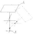
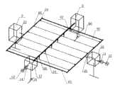
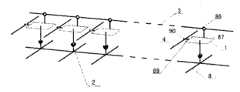
图1是本实用新型实施例一的3行×3列的跟踪太阳的机构的示意图 Fig. 1 is a schematic diagram of a mechanism for tracking the sun in 3 rows × 3 columns in
图2(a)是实施例一的单个太阳接收装置(反射镜)与立柱及行、列推拉杆等的连接示意图 Fig. 2 (a) is the connection schematic diagram of single solar receiving device (mirror) of embodiment one and column and row, column push-pull bar etc.
图2(b)是实施例一的单个太阳接收装置(反射镜)在列推拉杆推动下立柱和反射镜倾斜角度示意图 Fig. 2 (b) is a single solar receiving device (mirror) of embodiment one under the promotion of column push-pull rod and the schematic diagram of angle of inclination of reflector
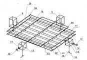
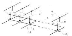
图3为实施例一的6行×7列的跟踪太阳的机构并将太阳光反射到位于框架阵列中央某处的接收塔上的接收器上的示意图 Fig. 3 is a schematic diagram of a 6-row x 7-column mechanism for tracking the sun in
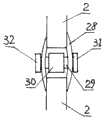
图4(a)为立柱与行、列方向的推拉杆的一种铰链结构示意图的正视图,图4(b)为侧面剖视图 Figure 4(a) is a front view of a hinge structure diagram of a column and push-pull rods in the row and column directions, and Figure 4(b) is a side sectional view
图5为3种一维转向支架的示意图,其中图5(a),图5(b),图5(c)分别为三种不同的一维转向支架的示意图 Figure 5 is a schematic diagram of three kinds of one-dimensional steering brackets, in which Figure 5(a), Figure 5(b), and Figure 5(c) are schematic diagrams of three different one-dimensional steering brackets
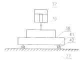
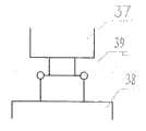
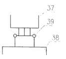
图6为推拉杆与基架联动装置的示意图,其中图6(a)为正视图,图6(b)为侧视图,图6(c)为另一种结构的侧视图,图6(d)为另一种结构的正视图,图6(e),图6(f),图6(g)分别为另外三种不同结构的正视图,图6(h)为连接轴与滑块相连接的结构示意图 Fig. 6 is the schematic diagram of push-pull rod and pedestal linkage, wherein Fig. 6 (a) is a front view, Fig. 6 (b) is a side view, Fig. 6 (c) is a side view of another structure, Fig. 6 (d ) is the front view of another structure, Figure 6(e), Figure 6(f), and Figure 6(g) are the front views of three other different structures, and Figure 6(h) is the connection between the shaft and the slider Schematic diagram of the connection
图7为基架与限制基架在高度方向上、下运动的限位套及沙袋或石块或类似物体的示意图,其中图7(a)为基架平面示意图,图7(b)为限位套的示意图,图7(c)为另一基架平面示意图 Fig. 7 is the sketch map of pedestal and the limit sleeve and sandbag or stone or similar object that limit pedestal in the height direction, wherein Fig. 7 (a) is the schematic plan view of pedestal, Fig. 7 (b) is the limiter The schematic diagram of the bit cover, Figure 7(c) is a schematic plan view of another base frame
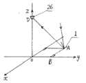
图8为确定反射镜初始角度的示意图 Figure 8 is a schematic diagram of determining the initial angle of the mirror
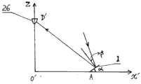
图9为图8中确定反射镜初始角度的坐标平移后的示意图 Fig. 9 is a schematic diagram after the coordinate translation of determining the initial angle of the reflector in Fig. 8
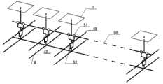
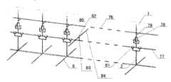
图10为实施例二的排成一行的多个太阳光接收装置的示意图 Fig. 10 is the schematic diagram of a plurality of solar light receiving devices lined up in embodiment two
图11为实施例二的跟踪太阳机构的示意图 Fig. 11 is the schematic diagram of the tracking sun mechanism of embodiment two
图12为实施例二的一排行转轴与列推拉杆及驱动器、联动机构的连结示意图 Figure 12 is a schematic diagram of the connection between a row of rotating shafts and a row of push-pull rods, drivers, and linkage mechanisms in
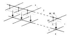
图13为实施例三的排成一行的多个太阳光接收装置示意图 Fig. 13 is a schematic diagram of a plurality of solar light receiving devices arranged in a row in embodiment three
图14为实施例三的跟踪太阳的机构示意图之一 Fig. 14 is one of the mechanism schematic diagrams of the tracking sun of embodiment three
图15为实施例三的跟踪太阳的机构示意图之二 Fig. 15 is the second of the mechanism schematic diagram of the tracking sun of embodiment three
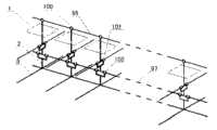
图16为实施例四的跟踪太阳的机构示意图,其中图16(a)为排成一行的多个太阳光接收装置示意图,图16(b)为多行太阳光接收装置的跟踪太阳机构的示意图 Fig. 16 is a schematic diagram of a mechanism for tracking the sun in
图17为实施例五的跟踪太阳机构示意图,其中图17(a)为排成一行的多个太阳光接收装置示意图,图17(b)和图17(c)分别为两种跟踪太阳的机构示意图 Figure 17 is a schematic diagram of the sun-tracking mechanism of
图18为实施例六的行、列推拉杆与太阳光接收装置等部件的连接和铰链结构示意图,其中图18(a),图18(b),图18(c),图18(d),图18(e),图18(f),图18(g),图18(h),图18(i),图18(j),图18(k)分别为11种不同的连接和铰链结构示意图 Figure 18 is a schematic diagram of the connection and hinge structure of the row and column push-pull rods and the solar light receiving device and other parts of embodiment six, wherein Figure 18 (a), Figure 18 (b), Figure 18 (c), Figure 18 (d) , Figure 18(e), Figure 18(f), Figure 18(g), Figure 18(h), Figure 18(i), Figure 18(j), Figure 18(k) are 11 different connections and Schematic diagram of hinge structure
图19为实施例七的行、列推拉杆与行、列转轴及其他部件等的连接和铰链结构示意图,其中图19(a),图19(b),图19(c),图19(d)分别为四种不同的连接和铰链结构示意图 Figure 19 is a schematic diagram of the connection and hinge structure of the row and column push-pull rods and the row and column shafts and other components of
图20为一种弧形滑槽的示意图 Figure 20 is a schematic diagram of an arc chute
具体实施方式Detailed ways
实施例一 Embodiment one
本实用新型的跟踪太阳的机构的实施例一的装置结构如图1所示,为了绘图简便及表达清楚,图1中只画出了3行×3列的框架阵列结构,图中的太阳光接收装置为反射镜,实际上行、列数量可以为任意个,接收装置可以为反射镜或透镜组件或反射镜与透镜的组合或太阳能光伏电池组件包括聚光电池组件或热能接收器等等,图1中装置包括9个太阳光接收装置1,9根支撑太阳光接收装置的分为两段的立柱2,3根相互平行的处于同一平面的行推拉杆3,3根相互平行位于同一平面的列推拉杆4,9个列推拉杆4与立柱2的铰链5,9个行推拉杆3与立柱2的铰链6,9个将立柱分为两段的万向节7,由3根与行推拉杆平行的杆和3根与列推拉杆平行的杆相互固定连结的基架8,立柱的下端固定连结在基架上,2个推拉杆与基架联动装置9,2根连结驱动器与行、列推拉杆框架的主轴10,2个安装在主轴10上的配重系统11,2个风速仪12,2个驱动器13,其轴线相交于框架阵列的相邻两边的中点,2个传感与控制系统14,2根连结驱动器底座与基架的杆15,4个转轴相互垂直的一维转向支架16,转向支架16的转轴至驱动器的驱动轴的距离与万向节转动接触点至太阳光接收装置的距离相等,可分别围绕相互垂直的两个转轴转动,行驱动器与对应的联动装置均安装在有相同转动方向的相同转向支架16上,同样的列驱动器与对应的联动装置也分别安装在有相同转动方向的相同转向支架16上,连结行推拉杆3的加宽加厚的承力杆17,连结列推拉杆4的加宽加厚的承力杆18,连结列推拉杆的连结杆19,连结行推拉杆的连结杆20,连结连接杆19与联动装置9的连结轴21,连结连接杆20与联动装置9的连结轴22,连接联动装置9的底 座与基架的连接杆23和24,图纸未画出限制基架运动的限位套和沙袋,将在后面单独说明。 The device structure of
图2(a)为单个太阳接收装置(反射镜)与立柱2及行推拉杆3,列推拉杆4,万向节7,基架8等的连接示意图,图2(b)为单个太阳接收装置(反射镜)在列推拉杆4推动下立柱2和反射镜倾斜角度示意图,反射镜与立柱及推拉杆的连接方式可以有许多种,后面将进一步给予说明。 Figure 2(a) is a schematic diagram of the connection of a single solar receiving device (reflector) with a
图3为6行×7列的装置,并将太阳光反射到位于框架阵列中央某处的接收塔25上的接收器26上的示意图,27为地面,图中为能看得清楚,只画出了部分立柱等,接收塔也可放置于框架阵列边沿某处,或将若干个框架阵列接收的太阳光反射到一个接收塔上的接收器上,接收器可以是任何一种太阳能利用装置,图中为了绘图简便只画出了6行×7列的装置示意图,实际上可以为任意行和任意列。 Fig. 3 is the device of 6 rows * 7 columns, and the schematic diagram that reflects sunlight to the
图4为立柱2与行、列方向的推拉杆3或4的一种铰链结构示意图,其中图4(a)为正视图,图4(b)为侧视图,图中28为连接两段立柱2的连接体,29为一圆轴,30为轴承,行推拉杆3固定连接在轴承30上,31和32为固定销,立柱与行、列推拉杆的铰链可以有许多种,如圆柱副等各种运动副,后面将再进一步予以说明。 Fig. 4 is a schematic diagram of a hinge structure of a
图5为三种一维转向支架的示意图,图5(a)中33为旋转轴,34为轴承,图5(b)中35为圆柱副,图5(c)中36为铰链(回转副),一维单轴转向支架也可以有许多种,限于篇幅,在此仅列举三种。 Fig. 5 is the schematic diagram of three kinds of one-dimensional steering brackets, 33 is a rotating shaft in Fig. 5 (a), 34 is a bearing, 35 is a cylinder pair in Fig. 5 (b), 36 is a hinge (revolving pair) in Fig. 5 (c) ), there can also be many kinds of one-dimensional single-axis steering brackets, and due to space limitations, only three are listed here. the
图6为推拉杆与基架联动装置9的示意图。其中图6(a)为联动装置9的侧视图,图中37为联动装置上面部分,是一有一圆弧形孔洞(侧面)和长方形(或其他形状)的开口(正面)的结构,联动装置的上半部分将由连接轴21(或22)带动做滑动并做转动运动,其转动半径与对应的驱动器在相应的一维转向支架上的转动半径相同,与行推拉杆相对应的联动装置的圆弧形孔洞的半径等于行推拉杆在与其平行方向的运动半径,与列推拉杆相对应的联动装置的圆弧形孔洞的半径等于列推拉杆在与其平行方向上的运动半径,长方形(或其他形状)的开口的长度(高度)与圆弧形孔洞相对应,一样高,宽度与连接轴21(或22)的宽度或直径一样,略大于也可,以连接轴21(或22)可以自由活动即可,38为联动装置9的底座,39为一维转向支架,40为一由两个与对应的联动装置的圆弧形孔洞的半径相同的圆弧段组成的滑块,其与连接轴21(或22)相连接,由于两者弧度相同,滑块40在圆弧形孔洞中紧贴其内壁滑动,其滑动行程由驱动器通过连接轴21(或22)控制,41为安装在联动装置底座上的滑轮,42为安装在地面或其他基座上的滑槽;图6(b)为联动装置9的正视图;图6(c)为装置9的另一种正视图,图6(b)与图6(c)两者的区别在于圆弧形孔洞的不同,前者的 圆弧形孔洞不是通孔,后者为通孔;图6(d)为另一种形状的联动装置,其中43为一维转向支架,44为连接联动装置上部与转向支架转轴的支撑杆,45为另一根支撑杆,其他与前述联动装置相似;图6(e),图6(f),图6(g)分别为三种一维转向支架;图6(h)为连接轴21(或22)与滑块40相连接的结构示意图。 FIG. 6 is a schematic diagram of the
图7为基架8与限制基架在高度方向上、下运动的限位套及沙袋或石块或类似物体的示意图,其中图7(a)为基架与限位套的示意图,图中46为限位套,限位套与地面或其他构件相连结;图7(b)为限位套示意图,限位套的作用是限制基架的上、下运动,基架可以在限位套中做前、后、左、右的移动,但其上、下运动限制在很小的范围,比如毫米量级或厘米量级,这只需使限位套的高度略大于基架的杆的厚度(高度)即可,47为将限位套与地面固定的桩或类似物;图7(c)为基架与限制基架运动的沙袋或石块或其他有一定重量的类似物体48的示意图,沙袋或石块或其他类似物48放在基架上面,限制基架的上、下运动,但基架可在前、后、左、右方向移动,用这种方法可不需要对基架进行土建安装,节省了土建安装材料和人工成本,特别是在土质疏松的地面,比如沙漠、草原、软土地带等地区可节省大量费用。 Fig. 7 is the schematic diagram of
本实施例的工作原理是:太阳相对于地球的入射角度通常用太阳的方位角和高度角来表示,也就是太阳在地球的经度方向和纬度方向的角度,这两个角度可将其投影分解到任意两个呈一定角度的方向,在本实施例中,这两个方向分别为行推拉杆方向和列推拉杆方向,它们的角度为相互垂直,即成90°夹角,将太阳的角度分解到行、列推拉杆的方向,若将行、列推拉杆分别放置在经度和纬度方向,则太阳投射到行、列推拉杆方向的角度分别为太阳相对于地球的经度方向和纬度方向的角度,也就是通常所说的方位角和高度角,为计算及控制角度方便,将行、列推拉杆放置于经度方向和纬度方向较好,虽然它们可放置于任意方向。本实施例的工作原理的具体实施办法是:通过驱动器13控制行、列推拉杆3和4的运动,行、列推拉杆3和4的运动使与推拉杆铰链的立柱2相对于地面发生角度变化,从而使位于立柱2上端的太阳接收装置1(在此处为反射镜)相对于地面发生角度变化,通过设定立柱和位于其上的太阳接收装置的初始角度及行、列推拉杆与立柱铰链位置至万向节7的距离,即可设定行、列推拉杆的行程和太阳接收装置的角度的变化关系,因此通过驱动器13控制行、列推拉杆的行程即可控制立柱2和位于立柱2上端的太阳接收装置的角度变化,而通过传感及控制系统14探测太阳的角度及其变化并输出控制信号控制驱动器13驱动行、列推拉杆3和4的行程即可控制位于立柱2上端的太阳接收装置1跟踪太阳。上述两个驱动器13互相拉动,一个驱动器运动,拉动另一个驱动器转动,转动角度与反射镜1(太阳光接收器)在相同方 向的转动角度相同。太阳接收装置的初始角度的确定:根据用途有不同的初始角度,如果为分散应用,太阳接收装置为平板光伏电池组件或聚光光伏电池组件或热能接收器等等,则需要将太阳接收装置自始自终对准太阳,因此这类应用时的初始角度必须正对太阳,初始角度的设定需根据当地地理位置即经度、纬度等确定,例如以某地某一日期的正午12点为设定基准,此时的初始角度为:经度方向的角度=0,纬度方向的角度=当地纬度+此日期此刻的太阳纬度偏移量,偏移量向南为负值,向北为正值,除计算外,也可现场校准;如果为集中应用,即将太阳接收装置如反射镜接收到的太阳光全部集中到位于框架阵列中的太阳光接收塔25上的接收器26上,则此时太阳接收装置1的初始位置(角度)应调整到能将太阳光集中到太阳光接收塔25上的接收器26上的角度,这一角度可根据太阳光接收塔25上的接收器26离地面的高度和某个太阳光接收装置1离接收塔25底部的距离计算出来,图8为确定反射镜初始角度的示意图,1为框架阵列中的某一太阳接收装置(反射镜),26为太阳光接收塔25上的接收器,以接收塔25与地面接触中心为坐标原点,做直角坐标,将x方向设定为纬度方向,y方向为经度方向,假设反射镜1处于A点,与坐标轴x、y的垂直距离为x0,y0,接收器26的离地面高度为h,以正午12点钟作为设定基准,此时反射镜1在经度方向(y方向)的初始角度为零(相对于垂直方向,下同),为方便计算在纬度方向的初始角度,可以将图8中的坐标做平移,将A点移动到x轴上,新坐标如图9所示,图中β为此地此时的太阳光在纬度方向的入射角与垂直方向的夹角,α假定为反射镜1在纬度方向与地面的夹角,此处O′D′=h,O′A=x0,根据平面镜反射原理和图中几何形状关系,不难得出:α=1/2[ctg-1h/x0-β],由此可见,此时此刻,反射镜1的初始角度相对于垂直方向分别为:在经度方向为零,在纬度方向为90°-α,即90°-1/2[ctg-1h/x0-β]。对分散应用即太阳接收装置1需要始终对准太阳的情况,行、列推拉杆的行程控制已如上述,对集中应用,即将所有的太阳接收装置1(反射镜)的光全部汇聚到太阳光接收塔25上的接收器26上的情况,此时由于平面镜的反射关系,反射镜的角度变化应等于太阳光的角度变化的二分之一,此时相应调整驱动器13驱动行、列推拉杆3和4的行程即可。 The working principle of this embodiment is: the sun’s incident angle relative to the earth is usually represented by the sun’s azimuth and altitude angle, that is, the angle of the sun in the longitude direction and latitude direction of the earth, and these two angles can decompose its projection To any two directions at a certain angle, in this embodiment, these two directions are respectively the direction of the row push-pull rod and the direction of the column push-pull rod, and their angles are perpendicular to each other, namely forming an included angle of 90°, and the angle of the sun Decomposed into the direction of the row and column push-pull rods, if the row and column push-pull rods are respectively placed in the longitude and latitude directions, then the angle projected by the sun to the direction of the row and column push-pull rods is the longitude direction and latitude direction of the sun relative to the earth. Angle, which is commonly referred to as azimuth and altitude, for the convenience of calculating and controlling the angle, it is better to place the row and column push-pull rods in the longitude direction and latitude direction, although they can be placed in any direction. The specific implementation method of the working principle of the present embodiment is: the movement of the row and column push-
本实施例的工作过程是:传感与控制系统14中的光电传感器(或其他方式)接收太阳光的入射角度信息,将此信息传递给14中的控制系统,14中的控制系统向驱动器13给出控制指令,控制驱动器13的动作,驱动器13的动作驱动行、列推拉杆3和4的运动,行、列推拉杆3和4的运动推拉立柱2改变角度,进而使立柱2上端的反射镜1改变角度,从而跟踪太阳的角度变化。 The working process of the present embodiment is: the photoelectric sensor (or other modes) in the sensing and
本实施例中,由于使用了如下设计而满足了实用新型的目的: In this embodiment, the purpose of the utility model is satisfied due to the use of the following design:
1、立柱用万向节分为两段,使得立柱的上部及安装于立柱上端的太阳光接收装置可绕相互垂直的两个方向(经纬度两个方向)的转轴转动; 1. The column is divided into two sections by universal joints, so that the upper part of the column and the solar light receiving device installed on the upper end of the column can rotate around the rotation axes in two directions perpendicular to each other (two directions of latitude and longitude);
2、行、列杆分别用三根杆平行放置且处于同一平面,行、列杆的一端分别用杆19和20连结,另一端用承力杆17或18连结,使其分别成为一整体,三根行杆和列杆分别都做相同的运动; 2. The row and row rods are respectively placed in parallel with three rods and are on the same plane. One end of the row and row rods is connected with
3、设计了加宽、加厚的承力杆17和18使得承力杆17和18不会因为驱动器的驱动而使杆件产生变形,从而影响到行和列杆的运动的统一性; 3. The widened and thickened load-
4、两个驱动器分别位于矩形框架阵列的相邻两边的中点,驱动器的驱动力轴线平分框架阵列,使得驱动器对框架阵列的驱动平衡对称; 4. The two drivers are respectively located at the midpoints of the adjacent two sides of the rectangular frame array, and the driving force axis of the driver bisects the frame array, so that the drive of the driver to the frame array is balanced and symmetrical;
5、两个驱动器分别安装在转轴相互垂直的一维转向支架上,且转向支架的转动轴至驱动器的驱动轴的距离与万向节转动接触点至太阳光接收装置的距离相等,两个驱动器中的任何一个的驱动将带动另一驱动器运动,并与立柱转动相同的角度,从而使两者协调运动,不会出现使行、列杆产生扭曲和各太阳光接收装置的转动角度的不一致的情况; 5. The two drivers are respectively installed on one-dimensional steering brackets whose rotation axes are perpendicular to each other, and the distance from the rotation axis of the steering bracket to the drive shaft of the driver is equal to the distance from the rotating contact point of the universal joint to the sunlight receiving device. The two drivers The drive of any one of them will drive the other driver to move and rotate at the same angle as the column, so that the two can move in harmony, and there will be no distortion of the row and column rods and the inconsistency of the rotation angle of each solar light receiving device. Condition;
6、由于有了基架8,使得连结与基架8的立柱2的下端与铰链于行、列杆3和4的立柱2的上端可随温差的变化而上下的位置做相同的变化,从而确保了各根立柱2的运动一致性和准确性,克服了温差对太阳光接收装置接收角度的影响; 6. Due to the
7、由于有了与两个驱动器对应的,也安装于相同或相似的一维转向支架的联动装置,从而使得行、列杆与基架在长度方向的变化同步进行,不仅消除了如上述的温差的影响,还消除了驱动器为对抗框架阵列自身重力和风压而施加的拉(压)应力使行、列杆的长度尺寸变化的影响,以及消除了由于行、列杆与立柱以及行、列杆之间铰链时的间隙误差,包括加工、安装等因素造成的误差,比如每个铰链处平均有一毫米的误差,则100个铰链就有可能产生10厘米的误差,从而确保了跟踪精度; 7. Due to the linkage device corresponding to the two drivers and also installed on the same or similar one-dimensional steering bracket, the changes in the length direction of the row, column rod and base frame are carried out synchronously, which not only eliminates the above-mentioned The influence of temperature difference also eliminates the influence of the driver to resist the tension (compression) stress imposed by the frame array's own gravity and wind pressure to make the length and size of the rows and columns change, and eliminates the influence of the row, column and column and the row and column. The gap error of the hinge between the rods, including the error caused by processing, installation and other factors. For example, if there is an average error of one millimeter at each hinge, then 100 hinges may produce an error of 10 cm, thus ensuring tracking accuracy;
8、由于有了基架8,不仅消除了如上述的温度、风压、自重产生的误差和加工、安装产生的误差,而且可实现工厂化的模块化生产及安装,及可将基架直接放在地面,在基架上放置若干沙袋石块或其他重物等限制基架的上、下运动,从而大量节省现有技术的框架阵列的现场安装费用,包括安装材料费用和人工费用,特别在土质较疏松的地区如沙漠、草原、软土地和风力较大地区等更能节省大量费用; 8. Thanks to the
本实施例中的配重系统11的作用是用一个配重块平衡框架阵列自身的重量,无论框架阵列处于何种状态,配重系统均可平衡掉框架阵列的重量,从而使驱动器不承担框架阵列的重力分力,减少驱动器的负荷,配重系统的原理就是杠杆原理,已有许多文献上记载有配重系 统,在此不再专门叙述。 The function of the
本实施例中的风速仪12将测得的风速数据输入传感与控制系统中,在风速小于某一设定的数值时,即风速不会对框架阵列的安全性造成破坏的风速上限值时,控制系统14不对驱动器13给出任何指令,当风速超过设定的数值时,控制系统14将对驱动器13给出指令使驱动器13驱动太阳光接收装置11的接收角成水平状态(对分散应用)或尽量成水平状态(对集中应用)。 The
实施例二 Example two
本实用新型的跟踪太阳的机构的实施例二的装置结构如图10和图11,图12所示,其中图10为排成一行的多个太阳光接收装置(此处为平面反射镜)的示意图,图10中49为行转轴,50为列转轴,51和52分别为轴承,排列方法与实施例一的一样,不同之处是,在实施例二中用转轴49和转轴50及轴承51和52代替了实施例一中的行推拉杆3和列推拉杆4,及行、列推拉杆与立柱2的铰链5和6,将若干个如图10所示的排成一行的太阳光接收装置组合起来,构成如图11所示的框架阵列,图12为一排行转轴49与列推拉杆54及驱动器,联动机构的连结示意图,图11中53为行推拉杆,连接驱动器13,和框架阵列的列转轴铰链及连接对应的转动机构9,与行推拉杆53相连结的驱动器和联动机构直接安装在地面上或其他与地面相连的构件上,54为连接驱动器13及和框架阵列中的行转轴50铰链及连接对应的联动机构9的列推拉杆,与列推拉杆54连接的驱动器和联动机构安装在一转轴与列推拉杆54垂直的一维转向支架上,55为连接行转轴49的摇杆,56为连接列转轴50的摇杆,57为摇杆55与行推拉杆53的铰链,58为摇杆56与列推拉杆54的铰链,为了绘画简便,图11中只画出了行、列转轴49、50与行、列推拉杆53、54及驱动器13等的互动关系,而没有画出其他构件,在上述图11中只画出了5行×5列的框架结构,实际上可以是任意行和列的数量,另外图11中只画出了一根行推拉杆53和一根列推拉杆54,实际上可分别用任意根,行、列推拉杆之间的连结方式如实施例一的一样。 The device structure of
本实施例的工作原理和过程是:传感和控制系统14接收太阳光的角度信息并向驱动器13发出控制指令,驱动器13根据指令驱动行、列推拉杆53、54运动,行、列推拉杆53、54分别通过摇杆55、56使列转轴50和行转轴49转动角度,从而带动立柱2做二维转动,立柱2的转动使位于其上端的太阳接收装置(反射镜)转动角度,适当设计驱动器13对推拉杆53、54的驱动行程及摇杆55,56的长度以及立柱2中行、列转轴49、50至反射镜的距离即可使反射镜按要求准确跟踪太阳,如同实施例一一样,本实施例中的太阳跟踪装置也可用于分散跟踪和集中跟踪,跟踪方法与实施例一类似,另外其他部件的工作原理如联动装置9,驱动 器13,基架8等等与实施例一是一样的,在此不再赘述。图11中推拉杆54可放在转轴50的下面,或用其它置放方法。 The working principle and process of this embodiment are: the sensing and
实施例三 Embodiment three
本实用新型的跟踪太阳的机构的实施例三的装置结构如图13和图14,图15所示,其中图13为排成一行的多个太阳光接收装置(此处为简便,画成平面反射镜)示意图,图14为多行如上述图13所示的接收装置用一根推拉杆驱动的示意图,图15为多行如上述图13所示的接收装置用三根推拉杆驱动的示意图。 The device structure of embodiment three of the mechanism for tracking the sun of the present utility model is shown in Fig. 13 and Fig. 14, as shown in Fig. 15, wherein Fig. 13 is a plurality of sunlight receiving devices arranged in a row (here is simple, drawn as a plane Reflector) schematic diagram, Fig. 14 is a schematic diagram of a multi-row receiving device driven by a push-pull rod as shown in Fig. 13 above, and Fig. 15 is a schematic diagram of a multi-row receiving device driven by three push-pull rods as shown in Fig. the
图13中61为转轴兼行推拉杆,62为推拉杆。 Among Fig. 13, 61 is a rotating shaft and a push-pull rod, and 62 is a push-pull rod. the
图14中59为圆柱副,63为连结杆,64为摇杆,与推拉杆62相连的驱动器和联动机构分别安装在一维转向支架上,其转轴与推拉杆62垂直,与转轴兼推拉杆61相连结的驱动器和联动机构直接安装在地面上或安装在地面的其他构件上,65为铰链,66为连结杆。 Among Fig. 14, 59 is a cylinder pair, 63 is a connecting rod, and 64 is a rocking bar. The driver and the linkage mechanism connected to each other with the push-
图15中67为连结杆,68为列推拉杆的加宽加厚的连接杆。 67 is connecting rod among Fig. 15, and 68 is the widening and thickening connecting rod of row push-pull rod. the
为了绘图简便和更清楚地表现主要问题,上述图14,图15没有画出太阳光接收器1,立柱2,基架8等等部件,驱动器及联动机构9也只用很简单的方框表示,实际上,本实施例中的上述零部件与实施例一中的是相同或相类似的,其工作原理和方法也相同或相类似,在此不再赘述。 In order to make the drawing simple and express the main problem more clearly, the above-mentioned Fig. 14 and Fig. 15 do not draw components such as the
本实施例的工作原理和过程是:传感和控制系统14接收太阳光角度信息并向驱动器13发出控制指令,驱动器13根据指令驱动转轴兼行推拉杆61运动,及驱动列推拉杆62运动,列推拉杆62的运动使转轴兼行推拉杆61转动,上述61的运动将带动立柱2做二维运动,从而使位于立柱2上的太阳光接收装置1做二维运动,即做二维角度转动,适当设计驱动器13对推拉杆兼转轴61,推拉杆62的驱动行程及摇杆64的长度,以及立柱2中转轴61和一维转向支架50,51的转轴至太阳光接收装置的距离即可使太阳光接收装置(比如反射镜)按要求准确跟踪太阳,如同实施例一一样,本实施例中的太阳跟踪装置也可用于分散跟踪和集中跟踪,跟踪方法与实施例一类似。 The working principle and process of this embodiment are: the sensing and
在图13,图14,图15中只画出了数量有限的行、列数,行、列推拉杆的数目也较少,实际上可以用任意数量的行、列数目及太阳光接收装置。 In Fig. 13, Fig. 14, in Fig. 15, have only drawn limited number of rows and columns, and the number of rows and columns push-pull rods is also less, in fact any number of rows, columns and sunlight receiving devices can be used. the
实施例四 Embodiment four
本实用新型的实施例四的装置结构如图16所示,其中图16(a)为排成一行的多个太阳光接收装置(反射镜)的示意图,图16(b)为多行如上述图16(a)所示的太阳光接收装置组合在一起的示意图。 The device structure of
图16(a)中69为行推拉杆,70为列推拉杆,71为摇杆,72为铰链,73为圆柱副,74为铰链,75为转轴与行推拉杆69垂直的一维转向支架。 In Fig. 16 (a), 69 is a row push-pull rod, 70 is a column push-pull rod, 71 is a rocker, 72 is a hinge, 73 is a cylinder pair, 74 is a hinge, and 75 is a one-dimensional steering bracket whose rotating shaft is perpendicular to the row push-
图16(b)中与列推拉杆70相连结的驱动器和联动机构分别安装在两个相同的转轴与列推拉杆70相垂直的一维转向支架上,与行推拉杆69相连结的驱动器和联动机构安装在地面也可安装在其它与地面相连结的构件上。 In Fig. 16 (b), the driver and the linkage mechanism connected with row push-
为了绘图简便,上述图16(b)没有画出其他部件,驱动器13和联动机构9也只用很简单的方框表示,本实施例中的其他部件与实施例一中的相同或相类似,其工作原理也相同或相似。 For ease of drawing, above-mentioned Fig. 16 (b) does not draw other parts, and
本实施例的工作原理和实施例一基本相同,不同之处是各有关参数不同,只需调整和设计有关参数即可使太阳光接收装置准确跟踪太阳,在此不再赘述。 The working principle of this embodiment is basically the same as that of
本实施例的用途与实施例一一样。 The purpose of this embodiment is the same as that of
本实施例的行、列数目也可以为任意数目。 The number of rows and columns in this embodiment can also be any number. the
实施例五 Embodiment five
本实用新型的实施例五的装置结构如图17所示,其中图17(a)为排成一行的多个太阳光接收装置(反射镜)的示意图,图17(b)为多行上述图17(a)所示的太阳光接收装置组合在一起的示意图,其中用一根列推拉杆84,图17(c)为多行上述图17(a)所示的装置组合在一起的用多根列推拉杆84驱动的示意图。 The device structure of
图17(a)中76为行推拉杆,77为转轴,78为圆柱副,79为铰链,80为摇杆,81为圆柱副, Among Fig. 17 (a), 76 is a row push-pull rod, 77 is a rotating shaft, 78 is a cylinder pair, 79 is a hinge, 80 is a rocking bar, and 81 is a cylinder pair,
82为铰链,83为摇杆,84为列推拉杆。 82 is a hinge, 83 is a rocking bar, and 84 is a row push-pull bar. the
图17(b)中与行推拉杆76相连结的驱动器和联动机构分别安装在两个相同的转轴与行推拉杆76相垂直的一维转向支架上,此两个转向支架安装在地面或其他与地面相连结的构件上,与列推拉杆84相连结的驱动器和联动机构安装在地面或其他与地面相连结的构件上。 In Fig. 17 (b), the driver and the linkage mechanism connected with the push-
为了绘图简便,上述图17(b)和图17(c)没有画出其他部件,驱动器13和联动机构9也只用简单的方框表示,本实施例中的其他部件与实施例一中的相同或相类似,其工作原理也相同或相类似。 For ease of drawing, above-mentioned Fig. 17 (b) and Fig. 17 (c) do not draw other parts, and
本实施例的工作原理与实施例三相似,不同之处是各有关参数不同,只需设计和调整有关参数即可使太阳光接收装置准确跟踪太阳,在此不再赘述。 The working principle of this embodiment is similar to the third embodiment, the difference is that the relevant parameters are different, only need to design and adjust the relevant parameters to enable the sunlight receiving device to accurately track the sun, which will not be repeated here. the
本实施例的用途与上述实施例一,实施例二,实施例三,实施例四一样。 The purpose of this embodiment is the same as that of the first embodiment, the second embodiment, the third embodiment and the fourth embodiment. the
本实施例的行推拉杆和转轴及列推拉杆的数目也可以为任意数目。 The number of row push-pull rods and rotating shafts and column push-pull rods in this embodiment can also be any number. the
实施例六 Embodiment six
本实用新型的实施例六的装置结构如图18及如图1所示。其中图18(a)至图18(g)为行、列推拉杆3、4在太阳光接收装置1(反射镜)的上部或与其在同一平面的排成一行的多个太阳光接收装置1(反射镜)的七种方式的示意图;图18(h)为将太阳光接收装置1(反射镜)用支撑架悬挂起来,行、列推拉杆3和4在反射镜1的下方的示意图;图18(i)至图18(k)为行、列推拉杆3和4一个在反射镜1的上方,一个在反射镜1的下方的三种方式的示意图。 The device structure of
图18(a)中1为反射镜,2为立柱,3为行推拉杆,4为列推拉杆,5为铰链,6为铰链,7为万向节,8为基架,这些与前述的实施例的标号均相同。 In Fig. 18 (a), 1 is a reflector, 2 is a column, 3 is a row push-pull rod, 4 is a column push-pull rod, 5 is a hinge, 6 is a hinge, 7 is a universal joint, and 8 is a base frame. These are the same as the aforementioned The reference numerals of the embodiments are all the same. the
图18(b)中85为行、列推拉杆3和4的铰链。 85 is the hinge of row and column push-
图18(c)中86为摇杆87与行推拉杆3的铰链,87为摇杆。 86 is the hinge of rocking
图18(d)中88为列推拉杆4与摇杆87的铰链。 88 is the hinge of row push-
图18(f)中89为列推拉杆4与反射镜1的连接杆,90为连接杆89与列推拉杆4的铰链。 Among Fig. 18 (f), 89 is the connecting rod of row push-
图18(h)中91为与行推拉杆3平行的支架,92为与列推拉杆4平行的支架,93为竖直支撑杆,94为万向节。 In Fig. 18 (h), 91 is a support parallel to row push-
上述图18(a)至图18(k)中的万向节7和94均可分别用两个转轴相互垂直且与行、列推拉杆3、4相互平行的一维转向支架或圆柱副或其他类似构件代替。 The
将多行如上述图18(a)至图18(k)的排成一行的多个太阳光接收装置(反射镜)组合成一如实施例一中的图1所示的框架阵列,即可使上述的多行×多列的太阳光接收装置(反射镜)准确跟踪太阳,不同之处是参数不同,只需设计和调整有关参数即可,这些参数的设计只是初等数学问题,一般工程技术人员可轻易做到,本实施例与上述实施例一的框架阵列的工作原理和方法及用途完全一样,只是有关参数不同,在此不再赘述。 Combining a plurality of rows of sunlight receiving devices (mirrors) arranged in a row such as the above-mentioned Fig. 18(a) to Fig. 18(k) into a frame array as shown in Fig. 1 in
图18中只列举了有限的几种方式,还有更多的类似方式,由于篇幅关系在此不再详述。 FIG. 18 only lists several limited methods, and there are more similar methods, which will not be described in detail here due to space constraints. the
实施例七 Embodiment seven
本实用新型的实施例七的装置结构如图19及如实施例五的示意图17(b),图17(c)所示,其中图19(a)和图19(b)均为列用推拉杆,行用转轴加推拉杆的方式,均位于太阳光接收装置的下方的两种方式。 The device structure of
图19(c)为列用推拉杆,行用转轴加推拉杆的方式,其中前者放在太阳光接收装置的上方,后者放在下方。 Fig. 19(c) is a column with a push-pull rod, and a row with a rotating shaft plus a push-pull rod, wherein the former is placed above the solar light receiving device, and the latter is placed below. the
图19(d)也是列用推拉杆,行用转轴加推拉杆的方式,不同之处是太阳光接收装置被用支架悬空吊起,转轴加推拉杆放在接收装置的上方,列推拉杆放在下方。 Fig. 19(d) also uses push-pull rods for columns, and the mode of adding push-pull rods for rows. below. the
图19(a)至图19(c)中95为列推拉杆,96为行推拉杆,97为转轴,98为摇杆,99为铰链,100为铰链,101为一维转向支架,102和103为圆柱副或轴承。 In Fig. 19(a) to Fig. 19(c), 95 is a column push-pull rod, 96 is a row push-pull rod, 97 is a rotating shaft, 98 is a rocker, 99 is a hinge, 100 is a hinge, 101 is a one-dimensional steering bracket, 102 and 103 is a cylinder pair or a bearing. the
图19(d)中104为万向节,105和106为平行推拉杆96和转轴97的水平支撑杆,107为竖直支撑杆,107安装在基架8上。 104 is a universal joint among Fig. 19 (d), 105 and 106 are horizontal support rods of parallel push-
分别将多行如上述图19(a)至图19(d)的排成一行的多个太阳光接收装置组合成类似如实施例五中的图17(b)或图17(c)所示的框架阵列,即可使上述的多行×多列的太阳光接收装置准确跟踪太阳,只不过上述图19(a)至图19(d)中各相关参数各不相同,且与实施例五中的图17(b)至图17(c)中所示装置的参数不同,设计和调整相关的参数即可,本实施例与上述实施例五的框架阵列的工作原理和方法及用途完全一样,在此不再赘述。 Respectively combine a plurality of rows of sunlight receiving devices arranged in a row as shown in Fig. 19(a) to Fig. 19(d) above into a structure similar to that shown in Fig. 17(b) or Fig. 17(c) in
图19中只列举了4种方式,还有更多的类似方式,由于篇幅关系在此不再详述。 Only 4 methods are listed in FIG. 19 , and there are more similar methods, which will not be described in detail here due to space constraints. the
上述实施例中的驱动器13安装在一维转向支架上,实际上不仅如此,还可安装在圆柱副转动轴上和弧形滑槽内以及其他任何一种能使驱动器绕某一轴向转动的构件上。 The
图20给出了一种弧形滑槽的示意图,图中108为弧形滑槽,此弧形滑槽为圆柱形的一段弧面,此圆柱的半径等于或近似等于对应的用一维转向支架16时的转向支架的转轴中心线至驱动主轴10的垂直距离,驱动器安装在圆弧滑槽内,在圆弧滑槽内沿滑槽做圆弧运动,其运动如同安装在一维支架上一样,是由另一边的驱动器的驱动行为牵引的,另外其自身也驱动主轴10运动。 Figure 20 shows a schematic diagram of an arc-shaped chute. 108 in the figure is an arc-shaped chute. The vertical distance from the center line of the rotating shaft of the steering bracket to the
上述实施例中的万向节均可分别用两个转轴相互垂直且与行、列推拉杆相互平行的一维转向支架或圆柱副或其他能使立柱在两个相互垂直的方向上转动的构件代替。 The universal joints in the above-mentioned embodiments can be used respectively with two rotating shafts perpendicular to each other and one-dimensional steering brackets or cylinder pairs or other components that can make the columns rotate in two mutually perpendicular directions. replace. the
上述实施例二至实施例七中的一维转向支架和铰链方式及其它部件如实施例一的一样,可以有许多种,为节省篇幅,上述实施例中只列出了一种。 The one-dimensional steering brackets, hinges and other components in the above-mentioned
以上七个实施例仅仅是本实用新型的多种实施例的一部分,限于篇幅,还有许多种实施例不再在此叙述。 The above seven embodiments are only a part of various embodiments of the present utility model, and due to space limitation, there are many other embodiments that will not be described here. the
Claims (3)
Translated fromChinesePriority Applications (1)
| Application Number | Priority Date | Filing Date | Title |
|---|---|---|---|
| CN2010205932705UCN202166897U (en) | 2010-10-19 | 2010-10-19 | Mechanism, pedestal and linkage device for tracking the sun |
Applications Claiming Priority (1)
| Application Number | Priority Date | Filing Date | Title |
|---|---|---|---|
| CN2010205932705UCN202166897U (en) | 2010-10-19 | 2010-10-19 | Mechanism, pedestal and linkage device for tracking the sun |
Publications (1)
| Publication Number | Publication Date |
|---|---|
| CN202166897Utrue CN202166897U (en) | 2012-03-14 |
Family
ID=45802713
Family Applications (1)
| Application Number | Title | Priority Date | Filing Date |
|---|---|---|---|
| CN2010205932705UExpired - Fee RelatedCN202166897U (en) | 2010-10-19 | 2010-10-19 | Mechanism, pedestal and linkage device for tracking the sun |
Country Status (1)
| Country | Link |
|---|---|
| CN (1) | CN202166897U (en) |
Cited By (9)
| Publication number | Priority date | Publication date | Assignee | Title |
|---|---|---|---|---|
| CN103956960A (en)* | 2014-05-15 | 2014-07-30 | 无锡同春新能源科技有限公司 | Solar photovoltaic power station increasing generating capacity through sun tracing energy-saving reflection boards |
| CN105099359A (en)* | 2015-08-11 | 2015-11-25 | 中国科学技术大学先进技术研究院 | Distributed light-gathering light-splitting solar energy comprehensive utilization system |
| CN107491103A (en)* | 2017-09-28 | 2017-12-19 | 合肥棠凯科技有限公司 | A kind of solar energy power generating plate bracing frame |
| CN109871037A (en)* | 2017-12-04 | 2019-06-11 | 亚太兆业有限公司 | Concentrator |
| CN112448664A (en)* | 2019-09-02 | 2021-03-05 | 南京工程学院 | Tracking type photovoltaic power generation system based on temperature change |
| EP3783413A4 (en)* | 2018-04-19 | 2022-01-12 | Asia Pacific Mega Trade Limited | ENERGY COLLECTION APPARATUS |
| CN114900113A (en)* | 2022-04-29 | 2022-08-12 | 北京玻锐特科技有限公司 | Photovoltaic power station traction daily system |
| CN115913077A (en)* | 2022-12-25 | 2023-04-04 | 连云港佳恩特能源科技有限公司 | Angle-adjustable photovoltaic support and installation and adjustment method thereof |
| CN120016920A (en)* | 2025-04-09 | 2025-05-16 | 特锐豪(陕西)新能源装备有限公司 | A connection structure for quick connection of photovoltaic panels |
- 2010
- 2010-10-19CNCN2010205932705Upatent/CN202166897U/ennot_activeExpired - Fee Related
Cited By (11)
| Publication number | Priority date | Publication date | Assignee | Title |
|---|---|---|---|---|
| CN103956960A (en)* | 2014-05-15 | 2014-07-30 | 无锡同春新能源科技有限公司 | Solar photovoltaic power station increasing generating capacity through sun tracing energy-saving reflection boards |
| CN105099359A (en)* | 2015-08-11 | 2015-11-25 | 中国科学技术大学先进技术研究院 | Distributed light-gathering light-splitting solar energy comprehensive utilization system |
| CN107491103A (en)* | 2017-09-28 | 2017-12-19 | 合肥棠凯科技有限公司 | A kind of solar energy power generating plate bracing frame |
| CN109871037A (en)* | 2017-12-04 | 2019-06-11 | 亚太兆业有限公司 | Concentrator |
| CN109871037B (en)* | 2017-12-04 | 2021-10-26 | 亚太兆业有限公司 | Light-gathering device |
| EP3783413A4 (en)* | 2018-04-19 | 2022-01-12 | Asia Pacific Mega Trade Limited | ENERGY COLLECTION APPARATUS |
| CN112448664A (en)* | 2019-09-02 | 2021-03-05 | 南京工程学院 | Tracking type photovoltaic power generation system based on temperature change |
| CN114900113A (en)* | 2022-04-29 | 2022-08-12 | 北京玻锐特科技有限公司 | Photovoltaic power station traction daily system |
| CN115913077A (en)* | 2022-12-25 | 2023-04-04 | 连云港佳恩特能源科技有限公司 | Angle-adjustable photovoltaic support and installation and adjustment method thereof |
| CN115913077B (en)* | 2022-12-25 | 2023-09-26 | 连云港佳恩特能源科技有限公司 | Angle-adjustable photovoltaic bracket and installation and adjustment method thereof |
| CN120016920A (en)* | 2025-04-09 | 2025-05-16 | 特锐豪(陕西)新能源装备有限公司 | A connection structure for quick connection of photovoltaic panels |
Similar Documents
| Publication | Publication Date | Title |
|---|---|---|
| CN202166897U (en) | Mechanism, pedestal and linkage device for tracking the sun | |
| CN102707729B (en) | A kind of mechanism following the tracks of the sun | |
| CN103324204B (en) | A kind of tracking support with double shafts | |
| US10326401B2 (en) | Tracking control systems for photovoltaic modules | |
| CN101663544A (en) | Double-shaft solar tracker | |
| JP4527803B1 (en) | Lightweight and thin solar concentrator that can be easily expanded in a plane | |
| CN102193560A (en) | Sun tracking mechanism and application thereof | |
| KR100922238B1 (en) | Solar power generation device | |
| KR20120123101A (en) | Automatic sunlight-tracking device | |
| CN208459859U (en) | A kind of large-sized photovoltaic square matrix numerical control rail mounted device day by day | |
| CN101173826A (en) | Sun tracing apparatus | |
| CN206077312U (en) | Array coordinated type solar energy two degrees of freedom tracking system | |
| WO2012119545A1 (en) | Heliostat device and corresponding heliostat system | |
| CN101976971A (en) | Vertical-horizontal linkage type solar clino-axis tracker mounting mechanism | |
| CN202014208U (en) | Linkage inclined shaft tracking mechanism with worm gear and worm arrays for solar utilization | |
| CN101976976A (en) | Steel cable type array linkage solar utilization diagonal axis tracking mechanism | |
| CN107565895A (en) | Water photovoltaic power station, water photovoltaic power generation system and its photovoltaic support | |
| CN110138326A (en) | A kind of novel biaxial photovoltaic tracking device | |
| CN106230366A (en) | Array coordinated type solar energy two degrees of freedom follows the tracks of system | |
| CN106094894A (en) | Solar energy tracking mutual ter axle twin columns robot | |
| CN204761380U (en) | Array biax linkage sun tracking means | |
| CN102087400B (en) | Heliostat and interlocking heliostat array device | |
| CN208226950U (en) | The swinging arm device of large span photovoltaic array tracking bracket | |
| CN107525284B (en) | Heliostat device | |
| CN112234923B (en) | Light-receiving support for tracking sun |
Legal Events
| Date | Code | Title | Description |
|---|---|---|---|
| C14 | Grant of patent or utility model | ||
| GR01 | Patent grant | ||
| CF01 | Termination of patent right due to non-payment of annual fee | Granted publication date:20120314 Termination date:20151019 | |
| EXPY | Termination of patent right or utility model |