CN202100152U - Door sill - Google Patents
Door sillDownload PDFInfo
- Publication number
- CN202100152U CN202100152UCN2011201004552UCN201120100455UCN202100152UCN 202100152 UCN202100152 UCN 202100152UCN 2011201004552 UCN2011201004552 UCN 2011201004552UCN 201120100455 UCN201120100455 UCN 201120100455UCN 202100152 UCN202100152 UCN 202100152U
- Authority
- CN
- China
- Prior art keywords
- door
- bolt
- gate
- fence
- side frame
- Prior art date
- Legal status (The legal status is an assumption and is not a legal conclusion. Google has not performed a legal analysis and makes no representation as to the accuracy of the status listed.)
- Expired - Fee Related
Links
- 230000000903blocking effectEffects0.000claimsdescription6
- 238000006073displacement reactionMethods0.000claims1
- 230000000694effectsEffects0.000description4
- 238000010586diagramMethods0.000description2
- 238000012986modificationMethods0.000description2
- 230000004048modificationEffects0.000description2
- 238000000034methodMethods0.000description1
Images


Classifications
- E—FIXED CONSTRUCTIONS
- E05—LOCKS; KEYS; WINDOW OR DOOR FITTINGS; SAFES
- E05B—LOCKS; ACCESSORIES THEREFOR; HANDCUFFS
- E05B65/00—Locks or fastenings for special use
- E05B65/0007—Locks or fastenings for special use for gates
- E—FIXED CONSTRUCTIONS
- E05—LOCKS; KEYS; WINDOW OR DOOR FITTINGS; SAFES
- E05C—BOLTS OR FASTENING DEVICES FOR WINGS, SPECIALLY FOR DOORS OR WINDOWS
- E05C1/00—Fastening devices with bolts moving rectilinearly
- E05C1/02—Fastening devices with bolts moving rectilinearly without latching action
- E05C1/06—Fastening devices with bolts moving rectilinearly without latching action with operating handle or equivalent member moving otherwise than rigidly with the bolt
- E—FIXED CONSTRUCTIONS
- E05—LOCKS; KEYS; WINDOW OR DOOR FITTINGS; SAFES
- E05C—BOLTS OR FASTENING DEVICES FOR WINGS, SPECIALLY FOR DOORS OR WINDOWS
- E05C19/00—Other devices specially designed for securing wings, e.g. with suction cups
- E05C19/16—Devices holding the wing by magnetic or electromagnetic attraction
- E—FIXED CONSTRUCTIONS
- E06—DOORS, WINDOWS, SHUTTERS, OR ROLLER BLINDS IN GENERAL; LADDERS
- E06B—FIXED OR MOVABLE CLOSURES FOR OPENINGS IN BUILDINGS, VEHICLES, FENCES OR LIKE ENCLOSURES IN GENERAL, e.g. DOORS, WINDOWS, BLINDS, GATES
- E06B9/00—Screening or protective devices for wall or similar openings, with or without operating or securing mechanisms; Closures of similar construction
- E06B9/02—Shutters, movable grilles, or other safety closing devices, e.g. against burglary
- E06B9/04—Shutters, movable grilles, or other safety closing devices, e.g. against burglary of wing type, e.g. revolving or sliding
- E—FIXED CONSTRUCTIONS
- E06—DOORS, WINDOWS, SHUTTERS, OR ROLLER BLINDS IN GENERAL; LADDERS
- E06B—FIXED OR MOVABLE CLOSURES FOR OPENINGS IN BUILDINGS, VEHICLES, FENCES OR LIKE ENCLOSURES IN GENERAL, e.g. DOORS, WINDOWS, BLINDS, GATES
- E06B9/00—Screening or protective devices for wall or similar openings, with or without operating or securing mechanisms; Closures of similar construction
- E06B2009/002—Safety guards or gates
Landscapes
- Engineering & Computer Science (AREA)
- Mechanical Engineering (AREA)
- Structural Engineering (AREA)
- Architecture (AREA)
- Civil Engineering (AREA)
- Physics & Mathematics (AREA)
- Electromagnetism (AREA)
- Gates (AREA)
- Extensible Doors And Revolving Doors (AREA)
- Securing Of Glass Panes Or The Like (AREA)
Abstract
Description
Translated fromChinese技术领域technical field
本实用新型涉及一种门栏,尤指一种具有磁铁可协助门栏定位的门栏。 The utility model relates to a gate fence, in particular to a gate fence with magnets which can assist the gate fence to be positioned. the
背景技术Background technique
一般家庭中,如果欲防范婴幼儿进入家中比较危险的区域,例如:厨房、浴室或阳台等,会利用安全门栏限制婴幼儿活动的范围,该安全门栏可以装设于连通至厨房等限制区域的出入口处,然为避免家长一时疏忽而未将该安全门栏仔细扣合锁上,造成婴幼儿仍自未关好的门栏缝隙推开走出,进入到危险性较高的区域,因此申请人于中国所申请申请号ZL201020139726「具有警示功能的门栏锁定装置」中,于门栏锁定装置上设有警示色板,当门栏确实闭锁时,警示色板会呈现一种颜色;当门栏未关好时,警示色板会呈现另一种颜色以警告使用者门栏并未确实关好。 In general families, if you want to prevent infants and young children from entering dangerous areas of the home, such as the kitchen, bathroom or balcony, etc., you will use the safety gate to limit the range of activities of infants and young children. At the entrance and exit, in order to prevent the parents from being negligent for a moment, they did not carefully fasten and lock the safety gate, causing infants and young children to push out from the gap of the unclosed gate and enter the dangerous area. Therefore, the applicant In China's application number ZL201020139726 "door locking device with warning function", a warning color plate is provided on the door locking device. When the door is really locked, the warning color plate will present a color; When closed, the warning color plate will show another color to warn the user that the door is not closed properly. the
但,若使用者推拉门栏的力量过大时,使用者可能会因一时疏忽认为门栏的警示色板已经呈现相对应的颜色代表门栏已经关好,却因为开关的冲力过大,尔后门栏的门锁又再次解除锁定,造成婴幼儿的安全仍有所虑,有鉴于此,现有门栏结构实有待进一步检讨,并谋求可行的解决方案。 However, if the force of the user pushing and pulling the door rail is too large, the user may think that the warning color plate of the door rail has shown the corresponding color to indicate that the door rail has been closed due to negligence. The door lock of the rear gate is unlocked again, causing the safety of infants and young children to still be considered. In view of this, the existing gate structure needs further review and seeks a feasible solution. the
实用新型内容Utility model content
本实用新型所要解决的主要技术问题在于,克服现有门栏结构有着定位性不足,造成门栏锁定性较差等缺点,而提供一种门栏,本实用新型的两磁铁分别设置于第一扣部以及第一栓部中,借由两磁铁之间的吸引力可协助该第一扣部与该第一栓部相互扣合锁定,避免因为开门或关门的力量过大造成该门锁装置没有确实锁定,本实用新型的枢纽部可提供一回复力协助该门栅回复至该门框的间,有助于该门锁装置锁定,本实用新型的挡块,可提高该门挡装置的挡片限制单一方向开启门栅的功 效,亦可借此降低门栅因开关的力量过大造成该门锁装置无确实锁定的机会。 The main technical problem to be solved by the utility model is to overcome the shortcomings of the existing gate structure, such as insufficient positioning and poor lockability of the gate, and provide a gate. The two magnets of the utility model are respectively arranged on the first In the buckle part and the first bolt part, the attractive force between the two magnets can assist the first buckle part and the first bolt part to snap and lock each other, so as to prevent the door lock device from being damaged due to the excessive force of opening or closing the door. If it is not locked, the hinge part of the utility model can provide a restoring force to assist the gate grid to return to the gap between the door frame, which is helpful for locking the door lock device. The stop block of the utility model can improve the stopper of the door stop device. The chip restricts the effect of opening the door grid in one direction, and can also reduce the chance of the door lock device not being locked due to excessive force of the switch. the
本实用新型解决其技术问题所采用的技术方案是: The technical scheme that the utility model solves its technical problem adopts is:
本实用新型提供一种门栏,其包含一门框、一门栅以及一门锁装置; The utility model provides a door fence, which includes a door frame, a door fence and a door lock device;
该门框,其包含一底座、一第一侧框以及一第二侧框,该底座两端分别地结合该第一侧框与该第二侧框,并令该第一侧框与该第二侧框垂直于该底座的长轴方向直立设置,该底座上设有一挡块; The door frame includes a base, a first side frame and a second side frame, the two ends of the base are respectively combined with the first side frame and the second side frame, and the first side frame and the second side frame The side frame is vertically arranged perpendicular to the long axis of the base, and a stopper is provided on the base;
该门栅,其设置于该门框上并与该门框相匹配,该门栅具有一第一端以及一第二端,该第一端与该第一侧框相对,该第二端与该第二侧框相对,该门栅的一侧以一枢纽部与该门框相互枢设地结合; The gate grid is arranged on the door frame and matched with the door frame, the gate grid has a first end and a second end, the first end is opposite to the first side frame, and the second end is opposite to the first side frame The two side frames are opposite to each other, and one side of the door grid is pivotally combined with the door frame by a hinge;
该门锁装置,其包含有至少一栓扣组合,各栓扣组合设置于门框的第一侧框与该门栅的第一端之间,并包含有一第一扣部以及一第一栓部,该第一扣部与该第一栓部为相对应扣合锁定,该第一扣部与第一栓部分别具有一磁铁,且该第一扣部的磁铁与该第一栓部的磁铁的设置位置为相对应且相互吸引。 The door lock device includes at least one bolt assembly, each bolt assembly is arranged between the first side frame of the door frame and the first end of the door grid, and includes a first buckle portion and a first bolt portion , the first buckle portion and the first bolt portion are engaged and locked correspondingly, the first buckle portion and the first bolt portion respectively have a magnet, and the magnet of the first buckle portion and the magnet of the first bolt portion The setting positions of are corresponding and attract each other. the
较佳的,该第一栓部具有一可弹复突伸的栓杆,该第一扣部具有一扣槽,该扣槽于垂直方向两端分别形成一斜面。 Preferably, the first bolt portion has a resiliently protruding bolt rod, the first buckle portion has a buckle groove, and the two ends of the buckle groove in the vertical direction respectively form a slope. the
较佳的,该枢纽部内部包含一弹性组件可提供一回复力令该门栅回复至位于该门框之间,且令该门栅有限度地作上、下方向的位移。 Preferably, an elastic component is included inside the hinge portion to provide a restoring force to return the gate grid to be located between the door frames, and to make the gate grid move up and down to a limited extent. the
较佳的,该门锁装置进一步设有一第二栓部以及一第二扣部,该第二栓部设置于该门栅第一端的底端以及该第二扣部设置于该门框底端相对应该第二栓部处,该第二栓部以及该第二扣部为相对应扣合。 Preferably, the door lock device is further provided with a second bolt and a second buckle, the second bolt is arranged at the bottom of the first end of the gate grid and the second buckle is arranged at the bottom of the door frame Corresponding to the second bolt portion, the second bolt portion and the second buckle portion are correspondingly fastened together. the
较佳的,进一步地设有一门栏装置,该门栏装置设置于该门栅上并与该挡块相对应,该门栏装置包含有两挡片,该两挡片可旋动至与该门框的底座以及挡块相互抵顶。 Preferably, a gate fence device is further provided, the gate fence device is arranged on the gate fence and corresponds to the stopper, the gate fence device includes two catch pieces, and the two catch pieces can be rotated to match the stopper. The base of the door frame and the stopper are against each other. the
借由本实用新型的门栏所提供的技术手段,可以达到下列优点及功效: With the technical means provided by the gate rail of the present utility model, the following advantages and effects can be achieved:
1.本实用新型的两磁铁分别设置于第一扣部以及第一栓部中,借由两磁铁之间的吸引力可协助该第一扣部与该第一栓部相互扣合锁定,避免因为开门或关门的力量过大造成该门锁装置没有确实锁定。 1. The two magnets of the present utility model are respectively arranged in the first buckle and the first bolt, and the attractive force between the two magnets can assist the first buckle and the first bolt to be locked together to avoid Because the force of opening or closing the door is too large, the door lock device is not locked properly. the
2.本实用新型的枢纽部可提供一回复力协助该门栅回复至该门框的间,有助于该门锁装置锁定。 2. The hinge part of the present invention can provide a restoring force to assist the gate grille to return to the space between the door frame and help the door lock device to lock. the
3.本实用新型的挡块,可提高该门挡装置的挡片限制单一方向开启门栅的功效,亦可借此降低门栅因开关的力量过大造成该门锁装置无确实锁定的机会。 3. The stopper of the present utility model can improve the effect of the stopper of the doorstop device to limit the opening of the gate grid in one direction, and can also reduce the chance of the door lock device not being locked due to excessive force of the switch. . the
附图说明Description of drawings
下面结合附图和实施例对本实用新型进一步说明。 Below in conjunction with accompanying drawing and embodiment the utility model is further described. the
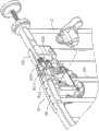
图1为本实用新型的门栏的立体外观示意图。 Fig. 1 is a schematic diagram of the three-dimensional appearance of the gate rail of the present invention. the
图2为本实用新型的门栏使用状态参考图。 Fig. 2 is a reference diagram of the use state of the gate fence of the present invention. the
图3为本实用新型的门锁装置的立体分解示意图。 Fig. 3 is a three-dimensional exploded schematic view of the door lock device of the present invention. the
图4为本实用新型的门锁装置的剖视图。 Fig. 4 is a sectional view of the door lock device of the present invention. the
图5为本实用新型的门锁装置及门挡装置的平面图。 Fig. 5 is a plan view of the door lock device and the door stopper device of the present invention. the
图6为本实用新型的门挡装置的立体外观示意图。 Fig. 6 is a schematic perspective view of the three-dimensional appearance of the doorstop device of the present invention. the
图中标号说明: Explanation of symbols in the figure:

具体实施方式Detailed ways
本实用新型是有关于一种门栏,请参见图1所示,其包含一门框10、一门栅20、一门锁装置30以及一门挡装置40。 The utility model relates to a door fence, as shown in FIG. 1 , which includes a
该门框10,其包含一底座11、一第一侧框12以及一第二侧框13, 该底座11两端分别与该第一侧框12以及该第二侧框13相互结合,并令该第一侧框12以及该第二侧框13垂直于该底座11的长轴方向设置,该底座11内侧设有一挡块112;该第一侧框12与该第二侧框13外侧分别设有至少一个以上的固定件111,该等固定件111可令该门框10固设定位于欲固设处,例如:通往厨房等较危险区域的出入口。 The
该门栅20,请参见图2所示,其与该门框10相匹配并且可活动的设置于该门框10的该第一侧框12、该第二侧框13与该底座10所围成的区域之间,且该门栅20的底端相对于门栅的底座11,该门栅20具有一第一端201、一第二端202以及间隔设置于该第一端201与第二端202之间的数杆体,该第一端201与该第一侧框12相对,该第二端202与该第二侧框13相对,该门栅20借由一枢纽部21与该第二侧框13相互枢设地结合,该枢纽部21可提供一回复力令该门栅20回复至该门框10之间,并且可令该门栅20有限度地作上、下方向的位移。 The
该门锁装置30,请参见图3至图5所示,其包含有至少一栓扣组合,在一较佳的具体实施例中,包含有二栓扣组合,各栓扣组合设置于门框10的第一侧框12与门栅20的第一端201之间,并包含一第一扣部301、一第一栓部302、一第二栓部303以及一第二扣部304,其中该第一扣部301与该第一栓部302为相对应设置,该第一栓部302设置于该第一侧框12顶端且相对应于该门栅20,该第一栓部302具有一可突伸于该第一栓部302外侧并复位至该第一栓部302内侧的栓杆3021以及一磁铁3022;该第一扣部301设置于该门栅20顶端相对应该第一栓部302处,该第一扣部301具有一扣槽3011以及一磁铁3012,该扣槽3011可令该栓杆3021卡固于其中,该扣槽3011为一呈凹陷状的槽体,该槽体于垂直方向的底端形成一斜面3013,借由该门栅20作相对于该门框10的上方位移,可令扣合于该扣槽3011的栓杆3021沿着该斜面3013滑出该扣槽3011中而解除锁定,该第一扣部301的磁铁3012的设置位置与该第一栓部302的磁铁3022相对应,借由该等磁铁3012、3022之间的吸引力,可协助该门栅20回复定位于该门框10之间;该第二栓部303设置于该门栅20底端相对于该第一侧框12处,其具有一可弹复突伸于该第二栓部303外侧的栓杆3031,该第二扣部304设置于该第一侧框12底端相对应于该第 二栓部303处,其具有一扣槽3041可令该第二栓部303的栓杆3031卡合于其中,该扣槽3041为一呈凹陷状的槽体,且于垂直方向的顶端形成为一斜面3042,借由该门栅20作相对于该门框10的上方位移,可令扣合于该扣槽3041的栓杆3031沿着其斜面3042滑出该扣槽中而解除锁定,当使用者手持该门栅20做相对于该门框10朝向上方位移时,可令该第一栓部302的栓杆3021脱离该第一扣部301的扣槽3011以及该第二栓部303的栓杆3031脱离该第二扣部304的扣槽,以解除该门锁装置30的锁定态样。 The
该门挡装置40,请参见图5及图6所示,其设置于该门栅20底端相对于该门框10的挡块112处,可限制该门栅20单向开启,该门挡装置40包含有两挡片401,该两挡片401分别地设置于该门栅20两侧面,该两挡片401可枢纽地朝向该底座11方向旋动,令一挡片401旋动至与该底座11以及该挡块112相互抵顶,可限制该门栅20以单一方向开启,且该挡块112可提高与该门栅20之间的摩擦力,有助于令该门栅20定位于该门框10之间。 The
以上所述仅是本实用新型的较佳实施例,并非对本实用新型作任何形式上的限制,虽然本实用新型已以较佳实施例揭露如上,然而并非用以限定本实用新型,任何熟悉本专业的技术人员,在不脱离本实用新型技术方案的范围内,当可利用上述揭示的技术内容作些许更动或修饰为等同变化的等效实施例,但凡是未脱离本实用新型的技术方案内容,依据本实用新型的技术实质对以上实施例作的任何简单修改、等同变化与修饰,均仍属于本实用新型技术方案的范围内。 The above descriptions are only preferred embodiments of the present utility model, and do not limit the utility model in any form. Although the utility model has been disclosed as above with preferred embodiments, it is not intended to limit the utility model. Anyone familiar with the utility model Professional technicians, without departing from the scope of the technical solution of the present utility model, can use the technical content disclosed above to make some changes or modify equivalent embodiments with equivalent changes, but all without departing from the technical solution of the present utility model Content, any simple modifications, equivalent changes and modifications made to the above embodiments according to the technical essence of the present utility model still belong to the scope of the technical solution of the utility model. the
Claims (5)
Translated fromChinesePriority Applications (2)
| Application Number | Priority Date | Filing Date | Title |
|---|---|---|---|
| CN2011201004552UCN202100152U (en) | 2011-04-08 | 2011-04-08 | Door sill |
| US13/166,642US20120255234A1 (en) | 2011-04-08 | 2011-06-22 | Safety gate |
Applications Claiming Priority (1)
| Application Number | Priority Date | Filing Date | Title |
|---|---|---|---|
| CN2011201004552UCN202100152U (en) | 2011-04-08 | 2011-04-08 | Door sill |
Publications (1)
| Publication Number | Publication Date |
|---|---|
| CN202100152Utrue CN202100152U (en) | 2012-01-04 |
Family
ID=45386169
Family Applications (1)
| Application Number | Title | Priority Date | Filing Date |
|---|---|---|---|
| CN2011201004552UExpired - Fee RelatedCN202100152U (en) | 2011-04-08 | 2011-04-08 | Door sill |
Country Status (2)
| Country | Link |
|---|---|
| US (1) | US20120255234A1 (en) |
| CN (1) | CN202100152U (en) |
Cited By (6)
| Publication number | Priority date | Publication date | Assignee | Title |
|---|---|---|---|---|
| CN103485700A (en)* | 2013-08-29 | 2014-01-01 | 浙江爱婴博士科技有限公司 | Adjustable safety door sill |
| CN104213787A (en)* | 2014-08-28 | 2014-12-17 | 浙江鑫博婴童用品有限公司 | Lower revolving shaft part for single doorsill |
| CN104790732A (en)* | 2015-02-12 | 2015-07-22 | 浙江鑫博婴童用品有限公司 | Door sill lock shell of door sill capable of being closed automatically |
| CN105178829A (en)* | 2015-09-30 | 2015-12-23 | 浙江丽童家居有限公司 | Automatic safe door sill |
| CN109025479A (en)* | 2018-08-06 | 2018-12-18 | 安徽澄小光智能科技有限公司 | Intelligent electronic fence system |
| US11585132B2 (en) | 2016-09-30 | 2023-02-21 | Barrette Outdoor Living, Inc. | Magnetic safety gate latch |
Families Citing this family (22)
| Publication number | Priority date | Publication date | Assignee | Title |
|---|---|---|---|---|
| US8607502B2 (en) | 2011-12-27 | 2013-12-17 | Carlson Pet Products, Inc. | Gate apparatus with springless automatic return gate |
| GB201211885D0 (en)* | 2012-07-04 | 2012-08-15 | Team Excel Dev Ltd | Securing means for a barrier and method of use thereof |
| US9637959B2 (en)* | 2013-10-11 | 2017-05-02 | Dorel Juvenile Group, Inc. | Security gate latch system |
| US10024080B2 (en)* | 2015-09-02 | 2018-07-17 | Elbee Pty Ltd. | Safety gate |
| CN205805369U (en)* | 2016-05-20 | 2016-12-14 | 奇立科技有限公司 | gate fence |
| US10458152B2 (en)* | 2016-06-06 | 2019-10-29 | Proofed, Inc. | Gate assembly employing a dual actuator latching mechanism |
| US10665048B1 (en)* | 2017-04-26 | 2020-05-26 | Jerome S. Heisler, Jr. | Apparatus and method for a balcony access status alert system |
| US10083557B1 (en)* | 2017-04-26 | 2018-09-25 | Jerome S. Heisler, Jr. | Apparatus and method for a balcony access status alert system |
| US11162300B1 (en) | 2017-08-02 | 2021-11-02 | Regalo International, Llc | Keeper apparatus to maintain gate in plane with frame |
| US11041340B1 (en)* | 2018-03-13 | 2021-06-22 | Regalo International, Llc | Gated barrier with one hand latch apparatus |
| CN108477928A (en)* | 2018-03-23 | 2018-09-04 | 段效钦 | A kind of fence for baby door |
| US11371264B2 (en)* | 2019-08-27 | 2022-06-28 | Ningbo Eudemon Child Protective Equipment Co., Ltd. | Fence gate limiting mechanism, fence gate assembly and fence gate limiting method |
| US11466512B2 (en)* | 2020-08-31 | 2022-10-11 | Beth Morris | Modular safety gate |
| CN215485407U (en)* | 2021-06-15 | 2022-01-11 | 中山市依家优品日用制品有限公司 | Coupling assembling and door guardrail, rail |
| USD987216S1 (en)* | 2021-06-16 | 2023-05-23 | Xianyi Zhao | Safety gate for pet |
| US11578529B1 (en)* | 2021-11-02 | 2023-02-14 | Regalo International, Llc | Gated barrier with lift lock |
| USD1008566S1 (en)* | 2023-04-10 | 2023-12-19 | Xianyi Zhao | Pet gate |
| USD1019005S1 (en)* | 2023-06-06 | 2024-03-19 | Shenzhen Yipinqu e-commerce Co., Ltd. | Expandable pet gate |
| USD1083147S1 (en)* | 2023-09-05 | 2025-07-08 | Zhongshan Yizhong Printing Co., Ltd. | Safety gate |
| USD1072278S1 (en)* | 2023-09-29 | 2025-04-22 | Zhongshan Yizhong Printing Co., Ltd. | Safety gate |
| USD1074072S1 (en)* | 2024-01-31 | 2025-05-06 | Jiarong Yang | Pet gate |
| USD1089711S1 (en)* | 2024-05-14 | 2025-08-19 | Zhongshan Ekar Uping Houseware Co., Ltd | Safety gate |
Family Cites Families (16)
| Publication number | Priority date | Publication date | Assignee | Title |
|---|---|---|---|---|
| US2293042A (en)* | 1941-05-22 | 1942-08-18 | Stone E Bush | Swinging door latch |
| US5362116A (en)* | 1990-08-13 | 1994-11-08 | David Doyle | Self latching magnetic latching device |
| GB9420715D0 (en)* | 1994-10-14 | 1994-11-30 | Beldray Ltd | Improvements relating to nursery gates |
| GB0030540D0 (en)* | 2000-12-14 | 2001-01-31 | Hicks Robert J | Safety barrier |
| US6666435B2 (en)* | 2001-01-23 | 2003-12-23 | Ivar V. Blosfelds | Self-closing gate for fence enclosures |
| US6588811B1 (en)* | 2002-12-03 | 2003-07-08 | Edward B. Ferguson | Reversible magnetic door stop/latch |
| ATE451534T1 (en)* | 2003-09-11 | 2009-12-15 | Baby Dan As | SAFETY BARRIER FOR CHILDREN WITH LOCKING DEVICE |
| CN1661189B (en)* | 2004-02-24 | 2010-12-15 | D&D集团有限公司 | Self-locking magnetic latching mechanism |
| US7322153B2 (en)* | 2004-08-27 | 2008-01-29 | Nitz Allen S | Baby gate |
| US7234739B2 (en)* | 2005-02-10 | 2007-06-26 | Washin Optical Co., Ltd. | Magnetic latch assembly |
| US7152372B2 (en)* | 2005-03-16 | 2006-12-26 | Shu-Chen Cheng | Gate |
| US7396056B2 (en)* | 2005-10-18 | 2008-07-08 | Shu-Chen Cheng | Childproof gate lock |
| US8136302B2 (en)* | 2006-08-25 | 2012-03-20 | James Trujillo | Safety gate |
| US7950184B2 (en)* | 2007-04-27 | 2011-05-31 | Carlson Pet Products, Inc. | Two-action gate requiring two steps to open |
| US7975431B2 (en)* | 2008-05-31 | 2011-07-12 | Carlson Pet Products, Inc. | Multiple piece gated pressurized barrier |
| US20110225890A1 (en)* | 2010-03-17 | 2011-09-22 | Mark Greenwood | Gate with foot-operated latching mechanism |
- 2011
- 2011-04-08CNCN2011201004552Upatent/CN202100152U/ennot_activeExpired - Fee Related
- 2011-06-22USUS13/166,642patent/US20120255234A1/ennot_activeAbandoned
Cited By (8)
| Publication number | Priority date | Publication date | Assignee | Title |
|---|---|---|---|---|
| CN103485700A (en)* | 2013-08-29 | 2014-01-01 | 浙江爱婴博士科技有限公司 | Adjustable safety door sill |
| CN104213787A (en)* | 2014-08-28 | 2014-12-17 | 浙江鑫博婴童用品有限公司 | Lower revolving shaft part for single doorsill |
| CN104790732A (en)* | 2015-02-12 | 2015-07-22 | 浙江鑫博婴童用品有限公司 | Door sill lock shell of door sill capable of being closed automatically |
| CN105178829A (en)* | 2015-09-30 | 2015-12-23 | 浙江丽童家居有限公司 | Automatic safe door sill |
| CN105178829B (en)* | 2015-09-30 | 2017-02-01 | 浙江丽童家居有限公司 | Automatic safe door sill |
| US11585132B2 (en) | 2016-09-30 | 2023-02-21 | Barrette Outdoor Living, Inc. | Magnetic safety gate latch |
| US12291904B2 (en) | 2016-09-30 | 2025-05-06 | Barrette Outdoor Living, Inc. | Magnetic safety gate latch |
| CN109025479A (en)* | 2018-08-06 | 2018-12-18 | 安徽澄小光智能科技有限公司 | Intelligent electronic fence system |
Also Published As
| Publication number | Publication date |
|---|---|
| US20120255234A1 (en) | 2012-10-11 |
Similar Documents
| Publication | Publication Date | Title |
|---|---|---|
| CN202100152U (en) | Door sill | |
| US8615928B2 (en) | Safety gate | |
| US8210127B2 (en) | Two-way door pet restriction device | |
| US9097050B2 (en) | Gate assembly | |
| CN201730511U (en) | A kind of infant protection door fence | |
| US20140318018A1 (en) | Mechanical swing gate | |
| CN101871311A (en) | Protective door fence for infants | |
| CN205349035U (en) | Stop device is opened to window | |
| KR100943543B1 (en) | Safe type door lock device | |
| CN203891734U (en) | gate fence | |
| US7396056B2 (en) | Childproof gate lock | |
| CN202090735U (en) | Push-to-Lock Aluminum Door and Window Stopper | |
| JP6853548B2 (en) | Doors and door devices | |
| CN111997456B (en) | Flat-open window clearance ventilation part | |
| CN212376481U (en) | A casement window clearance ventilation component | |
| KR200456204Y1 (en) | Lock on the safety window | |
| CN203669688U (en) | Automatic-reset safety door sill | |
| KR20120121506A (en) | A window fixing device | |
| CN217632180U (en) | Novel safety door sill | |
| CN203000003U (en) | Two-way drawer locker | |
| CN212225070U (en) | Novel door guardrail | |
| KR200450979Y1 (en) | Door handle | |
| CN203234335U (en) | Locking and positioning device for bidirectional drawer cabinet | |
| CN201133179Y (en) | Door sill opening and closing structure | |
| CN201771307U (en) | Aluminum door and window lock type opening limiter |
Legal Events
| Date | Code | Title | Description |
|---|---|---|---|
| C14 | Grant of patent or utility model | ||
| GR01 | Patent grant | ||
| CF01 | Termination of patent right due to non-payment of annual fee | ||
| CF01 | Termination of patent right due to non-payment of annual fee | Granted publication date:20120104 Termination date:20160408 |