CN202064367U - Insulating base for power tower - Google Patents
Insulating base for power towerDownload PDFInfo
- Publication number
- CN202064367U CN202064367UCN2010206902196UCN201020690219UCN202064367UCN 202064367 UCN202064367 UCN 202064367UCN 2010206902196 UCN2010206902196 UCN 2010206902196UCN 201020690219 UCN201020690219 UCN 201020690219UCN 202064367 UCN202064367 UCN 202064367U
- Authority
- CN
- China
- Prior art keywords
- foundation
- basis
- anode
- sacrificial anode
- sacrificial
- Prior art date
- Legal status (The legal status is an assumption and is not a legal conclusion. Google has not performed a legal analysis and makes no representation as to the accuracy of the status listed.)
- Expired - Lifetime
Links
Images


Landscapes
- Prevention Of Electric Corrosion (AREA)
Abstract
Translated fromChineseDescription
Translated fromChinese技术领域technical field
本实用新型涉及一种电力塔的绝缘基础,更具体地,涉及一种交流特高压同塔双回路绝缘基础型式中的牺牲阳极保护。The utility model relates to an insulation foundation of a power tower, in particular to a sacrificial anode protection in an AC UHV same-tower double-circuit insulation foundation type.
背景技术Background technique
在现有技术中,一般的工程基础型式都不考虑绝缘。然而,接地极址在故障、检修或单极运行时,会产生较大的地电流,在接地极址附近的杆塔基础由于长期受到接地极址附近地电流的影响,基础内部钢筋会被腐蚀。随着使用时间的增长,基础有可能会被破坏,最终导致立于基础之上的铁塔受到破坏,以至于破坏整条输电线路安全运行。In the prior art, insulation is not considered in general engineering foundation types. However, when the grounding pole is in fault, overhaul or single-pole operation, a large ground current will be generated. The tower foundation near the grounding pole will be affected by the ground current near the grounding pole for a long time, and the internal steel bars of the foundation will be corroded. As the use time increases, the foundation may be damaged, which will eventually lead to the destruction of the iron tower on the foundation, so as to destroy the safe operation of the entire transmission line.
当直流接地极距离高压输电线路较近时,会对附近的高压输电线路的基础中的钢筋有腐蚀作用。然而,由于以往输电线路均距离接地极址较远,故都未采取绝缘措施。当交流1000kV输电线路距离直流接地极址距离较近时,需要对该极址周围2km范围内的交流1000kV输电线路杆塔的基础采取绝缘措施。When the DC grounding electrode is close to the high-voltage transmission line, it will corrode the steel bars in the foundation of the nearby high-voltage transmission line. However, since the transmission lines were far away from the grounding poles in the past, no insulation measures were taken. When the distance between the AC 1000kV transmission line and the DC grounding pole is relatively close, it is necessary to take insulation measures for the foundation of the AC 1000kV transmission line tower within 2km around the pole.
实用新型内容Utility model content
如上所述,需要一种能够对输电线路塔的基础进行绝缘的装置,保护输电线路塔的基础免于受到地电流的腐蚀。As noted above, there is a need for a device capable of insulating the foundations of transmission line towers to protect the foundations of transmission line towers from corrosion by ground currents.
绝缘基础是在原有的基础形式上加装了阴极保护措施,把基础中的钢筋作为阴极,加装特殊材料制成阳极。当产生较大地电流时,先腐蚀基础之外的阳极,从而起到保护基础内部钢筋(阴极)的作用。进而保护整个杆塔基础。The insulation foundation is to add cathodic protection measures to the original foundation form. The steel bars in the foundation are used as cathodes, and special materials are added to make anodes. When a large ground current is generated, the anode outside the foundation is corroded first, so as to protect the internal reinforcement (cathode) of the foundation. And then protect the entire tower foundation.
根据本实用新型的一方面,提供了一种电力塔的绝缘基础,其特征在于,包括:从所述基础引出的引出连接,所述引出连接埋置于地下;接合到所述引出连接的牺牲阳极,所述牺牲阳极被埋置于地下,并被布置在所述基础的周围。According to one aspect of the present invention, there is provided an insulating foundation of a power tower, which is characterized in that it includes: an outgoing connection drawn from the foundation, the outgoing connection buried underground; a sacrificial connection connected to the outgoing connection An anode, the sacrificial anode is buried underground and arranged around the foundation.
根据本实用新型的一方面,所述牺牲阳极均匀地布置在所述基础的四周。According to one aspect of the present invention, the sacrificial anodes are evenly arranged around the foundation.
根据本实用新型的一方面,所述牺牲阳极在所述基础的每一侧的数量取决于电力塔的尺寸、电力塔的位置、基础中钢筋的数目、该塔所在位置的土壤电阻率以及可能的地电流的方向。According to an aspect of the invention, the number of said sacrificial anodes on each side of said foundation depends on the size of the power tower, the location of the power tower, the number of steel bars in the foundation, the resistivity of the soil where the tower is located and possibly the direction of the ground current.
根据本实用新型的一方面,所述牺牲阳极在所述基础的每一侧的数量为4-8个。According to an aspect of the present utility model, the number of sacrificial anodes on each side of the foundation is 4-8.
根据本实用新型的一方面,所述牺牲阳极与所述基础边缘的距离为0.5-1米。According to one aspect of the present utility model, the distance between the sacrificial anode and the edge of the foundation is 0.5-1 meter.
根据本实用新型的一方面,所述牺牲阳极是由比所述基础的材料更活泼的金属合金构成的。According to an aspect of the invention, the sacrificial anode is composed of a metal alloy that is more reactive than the material of the base.
根据本实用新型的一方面,所述牺牲阳极是镁合金牺牲阳极。According to an aspect of the utility model, the sacrificial anode is a magnesium alloy sacrificial anode.
根据本实用新型的一方面,所述牺牲阳极包括:布袋;置于所述布袋中的镁合金牺牲阳极;填充所述布袋的填充料;与所述镁合金牺牲阳极连接的密封接头;以及从所述密封接头引出的阳极电缆,所述阳极电缆接合到所述基础的引出连接。According to an aspect of the present utility model, the sacrificial anode includes: a cloth bag; a magnesium alloy sacrificial anode placed in the cloth bag; a filler to fill the cloth bag; a sealing joint connected with the magnesium alloy sacrificial anode; An anode cable exiting the sealing joint, the anode cable spliced to an exit connection of the foundation.
根据本实用新型的一方面,所述牺牲阳极是立式埋置于地下的。According to one aspect of the present utility model, the sacrificial anode is vertically buried underground.
如上所述,本实用新型的发明人创造性地提出了一种绝缘基础型式,其能够保护基础型式的钢筋免受电流的腐蚀,从而提高整个电力输送系统的安全性。As mentioned above, the inventors of the present utility model have creatively proposed an insulating foundation type, which can protect the steel bars of the foundation type from being corroded by electric current, thereby improving the safety of the entire power transmission system.
附图说明Description of drawings
以下将参考附图描述本实用新型,然而,应当理解,所附的附图仅仅是示意性的,附图中的各个部件并非一定是按比例绘制的。在附图中相同的附图标记表示相同的部件,其中:The present invention will be described below with reference to the accompanying drawings, however, it should be understood that the accompanying drawings are only schematic, and each component in the drawings is not necessarily drawn to scale. Like reference numerals refer to like parts in the drawings, wherein:
图1示意性地示出了根据本实用新型的一个实施例的电力塔基础与牺牲阳极的布置;Fig. 1 schematically shows the arrangement of a power tower foundation and a sacrificial anode according to an embodiment of the present invention;
图2示意性地示出了根据本实用新型的一个实施例的电力塔基础与牺牲阳极的布置的透视俯视图;以及Fig. 2 schematically shows a perspective top view of the arrangement of the power tower foundation and the sacrificial anode according to an embodiment of the present invention; and
图3示意性地示出了根据本实用新型的一个实施例的牺牲阳极的结构;Fig. 3 schematically shows the structure of a sacrificial anode according to an embodiment of the present invention;
图4示意性地示出了根据本实用新型的一个实施例的牺牲阳极与电力塔基础引出连接的接合的局部放大图。Fig. 4 schematically shows a partial enlarged view of the joint of the sacrificial anode and the outlet connection of the power tower foundation according to an embodiment of the present invention.
具体实施方式Detailed ways
在此将描述本实用新型的优选实施例,请参考随附的图示。于本实用新型所附的图示中,相同的参考标号即表示相同的结构元素。A preferred embodiment of the present invention will be described here, please refer to the accompanying drawings. In the drawings attached to the present utility model, the same reference numerals represent the same structural elements.
本实用新型提出了一种牺牲阳极的保护装置。借助该牺牲阳极,当在输电线路塔的基础附近产生较大的地电流时,该地电流将首先腐蚀该阳极,由此保护了作为阴极的输电线路塔基础。The utility model provides a sacrificial anode protection device. By means of the sacrificial anode, when a large ground current is generated near the foundation of the power transmission line tower, the ground current will first corrode the anode, thereby protecting the foundation of the power transmission line tower as the cathode.
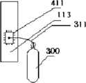
如图1所示,附图标记110表示地,附图标记111表示测试桩,附图标记112表示阴极电缆,附图标记113表示阳极电缆,附图标记114表示牺牲阳极,附图标记115表示填料,附图标记116表示接地网。As shown in FIG. 1 ,
如图1所示的实施例中,牺牲阳极采用的是镁合金阳极114,其立式埋设于地下。在一个实施例中,牺牲阳极埋置的深度为低于地平面至少1米,且距离接地网116不小于0.5米。每个基桩具有来自主筋基础的阳极引出连接113。每个牺牲阳极接合到该阳极引出连接113上。在一个实施例中,该引出连接113的材料可以采用热镀锌扁钢,例如采用-50×5热镀锌扁钢。阴极电缆112连接到接地网116。使用填料115包围牺牲阳极114防止物理流失和化学腐蚀。将填料和牺牲阳极置于地下。应当理解,对于此处的牺牲阳极与阴极保护引入点的接合可以采用各种方式,例如焊接。在焊接的情况下,需要确保焊接点被打磨干净、平整,露出金属色泽。按照放热焊接步骤进行上述焊接。连接点采用防腐涂料作防腐处理(如环氧树脂、石油沥青等)。在使用一段时间之后,可以通过测试桩111来测试牺牲阳极114的使用情况。In the embodiment shown in FIG. 1 , the sacrificial anode is a
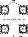
附图2示出了绝缘基础型式的透视俯视图。如图2所示,附图标记210表示电力塔基础。如图所示,各个牺牲阳极114通过引出连接布置在电力塔基础210的周围。在一个实施例中,牺牲阳极与电力塔基础边缘的距离为0.5-1米。然而,应当理解,上述距离范围不是必要的。只要能够使得牺牲阳极围绕电力塔基础,阻挡地电流腐蚀基础本身,则任何适当的距离都是可以采用。如图2所示,优选地,牺牲阳极114均匀地布置在电力塔基础210周围。然而,上述均匀布置并非是必要的,可以非均匀地布置牺牲阳极。例如,在地电流强度更大的一侧采用更密集的牺牲阳极布置,而在其他侧采用通常的布置。可以根据电力塔的尺寸、电力塔的位置、基础中钢筋的数目、该塔所在位置的土壤电阻率以及可能的地电流的方向来决定电力塔基础的每一侧上的牺牲阳极的数量的数目。例如,在皖电东送交流1000kV输电线路的电力塔基础中,在每一侧使用4-8个牺牲阳极。考虑地电流的大小、周围环境等其他因素,本领域技术人员结合本实用新型的教导完全可以根据其具体应用采用不同的牺牲阳极数量。应当理解,在基础的每一侧上也并不一定需要完全均匀的牺牲阳极布置。Figure 2 shows a perspective top view of an insulating foundation type. As shown in FIG. 2,
附图3示出了牺牲阳极的具体结构。如图3所示,附图标记310表示,附图标记311表示阳极电缆,附图标记312表示密封接头,附图标记313表示镁合金阳极,附图标记314表示布袋,附图标记315表示填料。在一个实施例中,牺牲阳极为镁合金阳极,形状为长条形。铸造镁合金阳极不应翘曲,其表面无毛刺,裂纹,气孔,夹杂物和附着物,缩孔,冷隔深度应不小于镁阳极厚度的10%。镁合金的成分还可以包括适量的铝、锰。Figure 3 shows the specific structure of the sacrificial anode. As shown in Figure 3, reference numeral 310 indicates,
尽管在本文中使用镁合金作为牺牲阳极的材料,然而应当理解,可以使用比基础的材料(通常为铁)更活泼的金属及其合金作为牺牲阳极,这样,在发生电流腐蚀时,将会首先腐蚀该电化学性质更活泼的牺牲阳极从而实现本实用新型的目的。例如,也可以使用锌合金。Although magnesium alloy is used as the sacrificial anode material in this paper, it should be understood that metals and alloys thereof that are more active than the base material (usually iron) can be used as sacrificial anodes, so that when galvanic corrosion occurs, the first The sacrificial anode with more active electrochemical properties is corroded to achieve the purpose of the utility model. For example, zinc alloys may also be used.
如图3所示,镁合金阳极313置于布袋314中,使用填料315填充布袋。使用密封接头312与镁合金阳极313连接,并从密封接头312引出阳极电缆311。如附图4所示,阳极电缆311将接合到电力塔基础的引出连接113上的接合区域411。As shown in FIG. 3 , a magnesium alloy anode 313 is placed in a cloth bag 314 , and a filler 315 is used to fill the cloth bag. The sealing joint 312 is used to connect with the magnesium alloy anode 313 , and the
如上所述,根据本实用新型的绝缘基础是在原有的基础形式上加装了阴极保护措施,把基础中的钢筋作为阴极,加装特殊材料制成了阳极。当较大地电流产生时,先腐蚀基础之外的阳极,从而起到保护基础内部钢筋(阴极)的作用。进而保护整个杆塔基础。As mentioned above, according to the insulation foundation of the utility model, cathodic protection measures are installed on the original foundation form, the steel bar in the foundation is used as the cathode, and the anode is made by adding special materials. When a large ground current is generated, the anode outside the foundation is corroded first, so as to protect the internal reinforcement (cathode) of the foundation. And then protect the entire tower foundation.
尽管已经参考特定实施例描述了本实用新型,应该理解实施例是示例性的,并且本实用新型的范围不局限于这些实施例。对上述实施例的多种变型、修改、附加以及改进都是可能的。应该预期这些变型、修改、附加以及改进落在如下面权利要求具体描述的本实用新型的范围内。Although the invention has been described with reference to specific embodiments, it should be understood that the embodiments are exemplary and that the scope of the invention is not limited to these embodiments. Various variations, modifications, additions and improvements to the above-described embodiments are possible. It is intended that such variations, modifications, additions and improvements fall within the scope of the invention as specifically described in the following claims.
Claims (9)
Priority Applications (1)
| Application Number | Priority Date | Filing Date | Title |
|---|---|---|---|
| CN2010206902196UCN202064367U (en) | 2010-12-30 | 2010-12-30 | Insulating base for power tower |
Applications Claiming Priority (1)
| Application Number | Priority Date | Filing Date | Title |
|---|---|---|---|
| CN2010206902196UCN202064367U (en) | 2010-12-30 | 2010-12-30 | Insulating base for power tower |
Publications (1)
| Publication Number | Publication Date |
|---|---|
| CN202064367Utrue CN202064367U (en) | 2011-12-07 |
Family
ID=45058233
Family Applications (1)
| Application Number | Title | Priority Date | Filing Date |
|---|---|---|---|
| CN2010206902196UExpired - LifetimeCN202064367U (en) | 2010-12-30 | 2010-12-30 | Insulating base for power tower |
Country Status (1)
| Country | Link |
|---|---|
| CN (1) | CN202064367U (en) |
Cited By (2)
| Publication number | Priority date | Publication date | Assignee | Title |
|---|---|---|---|---|
| CN107904602A (en)* | 2017-10-13 | 2018-04-13 | 西安理工大学 | A kind of device for preventing stray current corrosion underground utilities |
| CN110965065A (en)* | 2019-12-30 | 2020-04-07 | 苏州电力设计研究院有限公司 | Substation Grounding System |
- 2010
- 2010-12-30CNCN2010206902196Upatent/CN202064367U/ennot_activeExpired - Lifetime
Cited By (3)
| Publication number | Priority date | Publication date | Assignee | Title |
|---|---|---|---|---|
| CN107904602A (en)* | 2017-10-13 | 2018-04-13 | 西安理工大学 | A kind of device for preventing stray current corrosion underground utilities |
| CN107904602B (en)* | 2017-10-13 | 2019-09-27 | 西安理工大学 | A device for preventing stray current from corroding underground pipelines |
| CN110965065A (en)* | 2019-12-30 | 2020-04-07 | 苏州电力设计研究院有限公司 | Substation Grounding System |
Similar Documents
| Publication | Publication Date | Title |
|---|---|---|
| CN102808185B (en) | An anode assembly for an impressed current cathodic protection system | |
| CN101914773B (en) | Method and device for protecting power facility grounding net | |
| CN109136938B (en) | Anti-corrosion method for cathodic protection of underground pipelines | |
| CN106760870B (en) | A kind of anti-corrosion method of power transmission tower base | |
| CN106245039A (en) | A kind of cathodic protection ground connection based on sacrificial anode protection quota method | |
| CN201148467Y (en) | Combined anode and cathode protection apparatus | |
| CN202064367U (en) | Insulating base for power tower | |
| CN103668221A (en) | Transformer substation grounding grid corrosion prevention protection construction method | |
| CN208087751U (en) | A kind of sacrificial anode inbuilt steel buried pipeline anti-corrosive apparatus in groups | |
| CN203947161U (en) | Cathode protection structure of buried pipeline with heat-insulating layer | |
| CN205039503U (en) | Anticorrosive device of communication pipe | |
| CN202272956U (en) | Novel anti-corrosive grounding body with cathode protecting function | |
| CN207877869U (en) | A kind of underground oil and gas pipeline cathode protection device | |
| CN207483850U (en) | A kind of pipe cathode antiseptic project | |
| CN216808964U (en) | Electric anti-corrosion protection system for underground steel structure of power plant | |
| CN109957804A (en) | A Drainage Method for Buried Metal Pipes Near DC Grounding Electrodes | |
| CN111641096B (en) | Construction process of conductive polymer material grounding grid | |
| CN108963481A (en) | A kind of mounting process of deep foundation pit type electric power line pole tower earthing or grounding means | |
| CN104184015A (en) | Installation construction process for grounding device | |
| CN206654955U (en) | A kind of cathodic protection structure of cable-stayed bridge saddle anchoring section | |
| KR101480781B1 (en) | pole type protective potential test box for gas pipe | |
| CN107937921B (en) | A protective method for preventing direct current into the ground from corroding metal pipelines | |
| CN203625474U (en) | Power tower foundation protecting device | |
| CN223105654U (en) | A kind of anti-corrosion structure of gas pipeline under non-motor vehicle lane | |
| CN202989283U (en) | Pipeline anticorrosion device |
Legal Events
| Date | Code | Title | Description |
|---|---|---|---|
| C14 | Grant of patent or utility model | ||
| GR01 | Patent grant | ||
| C56 | Change in the name or address of the patentee | ||
| CP01 | Change in the name or title of a patent holder | Address after:100031 Xicheng District West Chang'an Avenue, No. 86, Beijing Patentee after:State Grid Corporation of China Patentee after:Co., Ltd of Huabei Power Design Inst., China Power Engineering Consulting Group Address before:100031 Xicheng District West Chang'an Avenue, No. 86, Beijing Patentee before:State Grid Corporation of China Patentee before:Huabei Power Design Inst., China Power Engineering Consulting Group | |
| CX01 | Expiry of patent term | ||
| CX01 | Expiry of patent term | Granted publication date:20111207 |