CN202057345U - Measuring and monitoring display - Google Patents
Measuring and monitoring displayDownload PDFInfo
- Publication number
- CN202057345U CN202057345UCN201120003337XUCN201120003337UCN202057345UCN 202057345 UCN202057345 UCN 202057345UCN 201120003337X UCN201120003337X UCN 201120003337XUCN 201120003337 UCN201120003337 UCN 201120003337UCN 202057345 UCN202057345 UCN 202057345U
- Authority
- CN
- China
- Prior art keywords
- circuit
- data
- sensor
- mmd
- input
- Prior art date
- Legal status (The legal status is an assumption and is not a legal conclusion. Google has not performed a legal analysis and makes no representation as to the accuracy of the status listed.)
- Expired - Fee Related
Links
- 238000012544monitoring processMethods0.000titleclaimsabstractdescription9
- 238000005259measurementMethods0.000claimsabstractdescription9
- 238000012545processingMethods0.000claimsabstractdescription3
- 238000010586diagramMethods0.000description18
- 244000261422Lysimachia clethroidesSpecies0.000description9
- 238000012360testing methodMethods0.000description8
- 230000006870functionEffects0.000description2
- 239000011521glassSubstances0.000description2
- 230000005484gravityEffects0.000description2
- 238000000034methodMethods0.000description2
- 239000008186active pharmaceutical agentSubstances0.000description1
- 238000009413insulationMethods0.000description1
- 238000012423maintenanceMethods0.000description1
- 230000004297night visionEffects0.000description1
- 238000012552reviewMethods0.000description1
Images


Landscapes
- Testing Or Calibration Of Command Recording Devices (AREA)
Abstract
Description
Translated fromChinese技术领域technical field
本实用新型涉及用于测量电的变量(electric variables)的仪器,具体地涉及配备有微处理器的所述仪器,该微处理器可以操纵所有连接的用于得到整个结合的最大效果的电路系统(circuitries)。(G06F 3/147)The utility model relates to an instrument for measuring electric variables, in particular to said instrument equipped with a microprocessor capable of manipulating all connected circuits for obtaining the maximum effect of the overall combination (circuits). (G06F 3/147)
背景技术Background technique
微处理器现在与一切结合,特别是与仪器结合。微型化的组件现在便宜且受欢迎。所以,新设计和生产的仪器像是有魔力的武器。因为很多组件/电路系统可以封装在有限的空间里,并且按微处理器的指令(instruction)运作,所以这将促使从前不可能的事情成为可能。Microprocessors are now integrated into everything, especially instruments. Miniaturized components are now cheap and popular. Therefore, the newly designed and produced instruments are like magic weapons. This will enable things that were not possible before as many components/circuitry systems can be packed in a limited space and operate under the instructions of a microprocessor.
过去,工人和仪器都构成旧式的(old-time)组织和实践。带着简易仪器的工人总是被派到工作点,例如,以检查建筑的配线。操作中,没人可以知道环境是什么样以及正在发生什么。并且结果必须由工人在他完成他的工作时报告。除他的口头报告之外没有记录可以保存。而现在,工人通常组织成团队。工作总是由整个团队完成。操作中,团队的领导必须知道他的团队中的每个工人在哪里,以及每个工作点的情况是什么样。还有,每个工作点正在发生什么?当然,团队中的每个工人也都必须知道他的邻近工作点正在发生什么。所以,旧式仪器不能满足该要求。In the past, both workers and instruments constituted old-time (old-time) organizations and practices. Workers with improvised instruments are always sent to the job site, for example, to check the wiring of a building. In operation, no one can know what the environment looks like and what is happening. And the results must be reported by the worker when he completes his work. No records are kept other than his oral report. Now, workers are often organized into teams. Work is always done by the whole team. In operation, the team leader must know where every worker on his team is and what the situation is like at each work point. Also, what is happening at each work point? Of course, each worker in the team must also know what is happening at his neighboring work sites. Therefore, legacy instruments cannot meet this requirement.
现在,建筑变得越来越大。配线变得更加复杂。在常规维护中,也应该考虑配线的环境。检查后,所有信息都应该保存以供以后参照。因此,本申请的发明人认为应该生产被称为测量及监控显示器(MMD)的新仪器。Now, buildings are getting bigger and bigger. Wiring becomes more complicated. During routine maintenance, the wiring environment should also be considered. After review, all information should be saved for future reference. Therefore, the inventors of the present application thought that a new instrument called a measurement and monitoring display (MMD) should be produced.
实用新型内容Utility model content
本实用新型的目的是提供一种计算机化的仪器,本仪器包括用于团队工人的足够微型化的组件。本仪器被命名为测量及监控显示器(MMD),本仪器具有以下功能:The object of the present invention is to provide a computerized instrument comprising sufficiently miniaturized components for team workers. This instrument is named Measuring and Monitoring Display (MMD), and this instrument has the following functions:
1.传送或接收通信;通过1. To transmit or receive communications; via
1)射频(RF);2)红外线(IR);3)蓝牙;4)激光;5)无线保真(WI-FI);6)互联网访问;7)接地或地线(ground)回路连接装置(MS-78WT系列)。1) Radio Frequency (RF); 2) Infrared (IR); 3) Bluetooth; 4) Laser; 5) Wireless Fidelity (WI-FI); 6) Internet access; 7) Ground or ground loop connection device (MS-78WT series).
2.显示;2. Display;
1)单色或彩色LCD;2)OLED;3)LED;4)投影;5)视频输出。1) Monochrome or color LCD; 2) OLED; 3) LED; 4) projection; 5) video output.
3.选择键;3. Select key;
1)触摸屏;2)按钮;3)感应键。1) Touch screen; 2) Button; 3) Sensor key.
4.存储器(可外扩的);4. Memory (expandable);
1)SD卡;2)记忆棒(Memory Stick)。1) SD card; 2) Memory Stick (Memory Stick).
5.内置传感器;(任一个或一些)5. Built-in sensor; (any one or some)
1)AC或DC电压;2)AC或DC电流;3)电阻;4)温度;5)湿度(humidity);6)水分(moisture);7)图像;8)角度;9)气体;10)红外温度。1) AC or DC voltage; 2) AC or DC current; 3) resistance; 4) temperature; 5) humidity; 6) moisture; 7) image; 8) angle; 9) gas; 10) Infrared temperature.
7.通信;与7. Correspondence; with
1)MEET系列产品,即DMMD;DMD;DS系列;1) MEET series products, namely DMMD; DMD; DS series;
2)移动电话(通过蓝牙);2) Mobile phone (via Bluetooth);
3)笔记本或台式计算机(通过蓝牙)。3) Laptop or desktop computer (via Bluetooth).
8.照片捕捉;8. Photo capture;
1)即时的单个照片;2)影片。1) Instant single photo; 2) Video.
9.具有音频声音的记录系统;9. Recording system with audio sound;
1)具有日期;日子;时间;地点(输入信息);测量或测试结果的独立的单个快拍。1) Independent single snapshot with date; day; time; location (input information); measurement or test result.
2)具有日期;日子;时间;地点(输入信息);测量或测试结果;可听见声音的影片。2) Movie with date; day; time; location (input information); measurement or test result; audible sound.
10.可听见声音;10. Audible sound;
1)预记录的;2)即时效果;3)对讲机。1) pre-recorded; 2) instant effects; 3) walkie-talkie.
11.数据或信号I/O端口;11. Data or signal I/O port;
1)感测类型;2)直接接触;3)USB端口;4)I/O端口;1) Sensing type; 2) Direct contact; 3) USB port; 4) I/O port;
5)RF或IR或蓝牙端口。5) RF or IR or Bluetooth port.
12.G(重力)传感器;12. G (gravity) sensor;
1)照片旋转;2)翻动照片;3)角度测量;4)数据呈报或发送。1) Photo rotation; 2) Flip photos; 3) Angle measurement; 4) Data reporting or sending.
为实现上述目的,本实用新型的MMD包括用于处理所有通过写入的程序检测到的信息的MCU,所述MCU进一步包括或连接以下电路系统:具有天线的RF或RFID或IR或蓝牙模块;具有闪光灯的照相机模块,连接到所述RF或RFID或IR或蓝牙模块;数据或信号输入电路,连接到所述RF或RFID或IR或蓝牙模块和所述照相机模块;经其传送或接收数据或信号的接地或地线(ground)回路连接装置(MS-78WT系列);多传感器输入信号数据电路,其连接接触或非接触型传感器;DMM或DMMD电路,其进一步连接所述多传感器输入信号数据电路;直接数据或信号输入电路,其进一步连接所述DMD或DMMD电路;LCD或LED或OLED显示电路;触摸屏或按钮或感应键输入选择电路,其进一步连接所述LCD或LED或OLED显示;图像处理器,其连接视频输入或输出电路、G传感器、快照电路、短片快照电路、外部存储器电路、以及数据或信号输入电路;声频或声音发生器;振动指令电路;USB端口;I/O端口;电源电路。In order to achieve the above object, the MMD of the present utility model includes an MCU for processing all information detected by the written program, and the MCU further includes or connects the following circuit systems: an RF or RFID or IR or bluetooth module with an antenna; A camera module with a flash connected to said RF or RFID or IR or Bluetooth module; a data or signal input circuit connected to said RF or RFID or IR or Bluetooth module and said camera module; transmitting or receiving data therethrough or Signal grounding or ground (ground) loop connection device (MS-78WT series); multi-sensor input signal data circuit, which connects contact or non-contact type sensors; DMM or DMMD circuit, which further connects the multi-sensor input signal data Circuit; direct data or signal input circuit, which is further connected to the DMD or DMMD circuit; LCD or LED or OLED display circuit; touch screen or button or sensor key input selection circuit, which is further connected to the LCD or LED or OLED display; image Processor, which is connected to video input or output circuit, G sensor, snapshot circuit, video snapshot circuit, external memory circuit, and data or signal input circuit; audio frequency or sound generator; vibration command circuit; USB port; I/O port; power circuit.
附图说明Description of drawings
图1(a)-图1(k)是用于示出主要部件的本实用新型的MMD的第一实施例的投影图和透视图。Figures 1(a)-1(k) are projected and perspective views of a first embodiment of the MMD of the present invention for illustrating main components.
图2是图1(a)-图1(k)所示的MMD的框图。Figure 2 is a block diagram of the MMD shown in Figures 1(a)-1(k).
图3(a)-图3(i)是图1(a)-图1(k)所示的具有夹持(clamp-on)装置的MMD的投影图和透视图。Figures 3(a)-3(i) are projected and perspective views of the MMD with the clamp-on device shown in Figures 1(a)-1(k).
图4(a)-图4(i)是图1(a)-图1(k)所示的具有系带(tie-band)装置的MMD的投影图和透视图。4(a)-4(i) are projected and perspective views of the MMD with the tie-band device shown in FIGS. 1(a)-1(k).
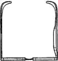
图5(a)-图5(i)是图1(a)-图1(k)所示的具有眼镜(spectacle)装置的MMD的投影图和透视图。Figures 5(a)-5(i) are projected and perspective views of the MMD with the spectacle device shown in Figures 1(a)-1(k).
图6是本实用新型的MMD的第二实施例的框图。Fig. 6 is a block diagram of a second embodiment of the MMD of the present invention.
图7(a)-图7(i)是安装在接着有伸缩杆(telescopic rod)的鹅颈管(gooseneck)上的第二实施例的MMD的一种形式。Figures 7(a)-7(i) are a version of the MMD of the second embodiment mounted on a gooseneck followed by a telescopic rod.
图8(a)-图8(j)是安装在接着有伸缩杆的鹅颈管上的第二实施例的MMD的另一种形式。Figures 8(a)-8(j) are another version of the MMD of the second embodiment mounted on a gooseneck followed by a telescoping rod.
图9(a)-图9(i)与图7(a)-图7(i)相似,除鹅颈管换成可延伸结构之外。Fig. 9(a) - Fig. 9(i) are similar to Fig. 7(a) - Fig. 7(i), except that the gooseneck is replaced with an extendable structure.
图10(a)-图10(j)是安装在折尺(folding rule)上的图9(a)-图9(i)所示的MMD。Figure 10(a)-Figure 10(j) is the MMD shown in Figure 9(a)-Figure 9(i) installed on a folding rule.
图11(a)-图11(j)是安装在鹅颈管上的图9(a)-图9(i)所示的MMD。Figures 11(a)-11(j) are the MMD shown in Figures 9(a)-9(i) mounted on a gooseneck.
图12是本实用新型的MMD的第三实施例的框图。Fig. 12 is a block diagram of a third embodiment of the MMD of the present invention.
图13(a)-图13(d)是根据图12的框图的MMD的一种形式。13(a)-13(d) are one form of MMD according to the block diagram of FIG.
图14是根据图12的框图的MMD的另一种形式。FIG. 14 is another form of MMD according to the block diagram of FIG. 12 .
图15是根据图12的框图的MMD的另一种形式。FIG. 15 is another form of MMD according to the block diagram of FIG. 12 .
图16是根据图12的框图的MMD的另一种形式。FIG. 16 is another form of MMD according to the block diagram of FIG. 12 .
图17是根据图12的框图的MMD的另一种形式。FIG. 17 is another form of MMD according to the block diagram of FIG. 12 .
具体实施方式Detailed ways
下面参照图1;图1是用于示出主要部件的本实用新型的MMD的第一实施例的投影图和透视图。本实用新型的MMD为万用表的形式。其中,10是具有/没有触摸屏的LCD/OLED。11是功能选择键。12是产生音频声音的扬声器。13是测试线(test leads)。14是照相机。15是闪光灯。16是传感器。17是投影镜头。18是IR模块。19是USB端口。20是I/O端口。21是SD存储插孔。22是DC输入插孔。G(重力)传感器安装在壳体中并且不能从外部看到。该重力传感器用于测量倾角,并且也用于照片旋转、翻动照片和数据呈报/发送。Referring now to FIG. 1 ; FIG. 1 is a perspective view and a perspective view of a first embodiment of the MMD of the present invention for illustrating main components. The MMD of the utility model is in the form of a multimeter. Among them, 10 is LCD/OLED with/without touch screen. 11 is a function selection key. 12 is a speaker for producing audio sound. 13 is a test line (test leads). 14 is a camera. 15 is a flashing light. 16 is a sensor. 17 is projection lens. 18 is an IR module. 19 is a USB port. 20 is an I/O port. 21 is an SD storage jack. 22 is a DC input jack. The G (gravity) sensor is installed in the housing and cannot be seen from the outside. The G-sensor is used to measure tilt and is also used for photo rotation, photo flipping and data presentation/sending.
参照图2;图2是图1所示的MMD的框图。图2中示出了MCU。该MCU是本实用新型的MMD的核心。该MCU的型号为No.MS-MMD 100,并由香港的MEET有限公司制造。该MCU用于处理所有通过写入的程序检测到的信息,所述MCU进一步包括/连接以下电路系统:具有天线的RF/RFID/IR/蓝牙模块;具有闪光灯的照相机模块,连接到所述RF/RFID/IR/蓝牙模块;数据/信号输入电路,连接到所述RF/RFID/IR/蓝牙模块和所述照相机模块;经其传送/接收数据/信号的接地/地线回路连接装置(MS-78WT系列);多传感器输入信号数据电路,其连接接触/非接触型传感器;DMD/DMMD电路,其进一步连接所述多传感器输入信号数据电路;直接数据/信号输入电路,其进一步连接所述DMD/DMMD电路;LCD/LED/OLED显示电路;触摸屏/按钮/感应键输入选择电路,其进一步连接所述LCD/LED/OLED显示;图像处理器,其连接视频输入/输出电路、G传感器、快照电路、短片快照电路、外部存储器电路、以及数据/信号输入电路;声频/声音发生器;振动指令电路;USB端口;I/O端口;电源电路。Referring to FIG. 2 ; FIG. 2 is a block diagram of the MMD shown in FIG. 1 . The MCU is shown in FIG. 2 . This MCU is the core of the MMD of the utility model. The model number of this MCU is No.MS-
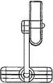
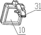
图3是图1所示的具有夹持装置的MMD的投影图和透视图。31是夹具或夹子。因此,该MMD可以夹在帽檐上或别处。现在用户的双手自由了。Figure 3 is a projected and perspective view of the MMD shown in Figure 1 with a clamping device. 31 is a jig or clip. Thus, the MMD can be clipped to the bill of the hat or elsewhere. Now the user's hands are free.
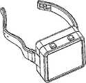
图4是图1所示的具有系带装置的MMD的投影图和透视图。32是系带。所以该MMD可以像腕表一样固定在人的胳膊上。FIG. 4 is a projected and perspective view of the MMD with the strap device shown in FIG. 1 . 32 is a tie. So the MMD can be fixed on a person's arm like a watch.
图5是图1所示的具有眼镜装置的MMD的投影图和透视图。33是眼镜的框架。屏幕10可以设计成作为整个镜片或镜片的一部分。FIG. 5 is a projected view and a perspective view of the MMD with the glasses device shown in FIG. 1 . 33 is the frame of glasses. The
操作中,例如,总共4人的电工团队全部配备有该MMD,他们中的任一人去地下室检查损坏的配线。其他三人在一层、二层和三层工作。他们中的每个人都可以看到其他人所看到的。当第一人到达地下室时,那里黑暗且潮湿。配线铺设在腐烂的墙板上。然后,其他三人可以知道所述木板的湿度、而且知道配线的温度、以及绝缘材料的电阻等等。他们中的一个可以容易地将该信息存储到插在他自己的MMD中的记忆棒里。或者可以将该信息传送到三层中的计算机中。在他们中的一个面对难题(例如复杂的电路)时,其他三人可以看到该电路并给予建议。所以,该MMD促使整个团队总是共同工作。工作效率将提高到非常高的水平。In operation, for example, a total of 4 electrician teams are all equipped with the MMD, and any one of them goes to the basement to check for damaged wiring. The other three worked on the first, second and third floors. Each of them can see what the others see. When the first person reached the basement, it was dark and damp. Wiring was laid on rotting siding. The other three can then know the humidity of the board, but also the temperature of the wiring, and the resistance of the insulation, and so on. One of them can easily store this information on a memory stick inserted in his own MMD. Or the information can be passed to a computer in the third tier. When one of them faces a difficult problem, such as a complex circuit, the other three can see the circuit and give advice. So, the MMD pushes the whole team to always work together. Work efficiency will increase to a very high level.
图6是本实用新型的MMD的第二实施例的框图。该框图与图2所示的框图相似,除由于经济原因,组件少于第一实施例,并且因此成本是第一实施例的一半之外。Fig. 6 is a block diagram of a second embodiment of the MMD of the present invention. The block diagram is similar to that shown in Figure 2, except that for economical reasons there are fewer components than the first embodiment, and therefore the cost is half that of the first embodiment.
图7是安装在接着有伸缩杆的鹅颈管上的第二实施例的MMD的一种形式。该图中,41是鹅颈管,42是伸缩杆,43是非接触温度传感器,44是气体/湿度传感器,45是白色LED,并且46是用于热成像(thermographic)/夜视的CCD照相机。18’是IR LED。Figure 7 is a version of the MMD of the second embodiment mounted on a gooseneck followed by a telescoping rod. In this figure, 41 is a gooseneck, 42 is a telescoping rod, 43 is a non-contact temperature sensor, 44 is a gas/humidity sensor, 45 is a white LED, and 46 is a CCD camera for thermographic/night vision. 18' is the IR LED.
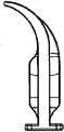
图8是安装在接着有伸缩杆的鹅颈管上的第二实施例的MMD的另一种形式。该图中,51是用于水分测量的测试触针(test pin)。Figure 8 is an alternative version of the MMD of the second embodiment mounted on a gooseneck followed by a telescoping rod. In this figure, 51 is a test pin (test pin) for moisture measurement.
图9与图7相似,除鹅颈管换成可延伸结构之外。Figure 9 is similar to Figure 7, except that the gooseneck is replaced with an extendable structure.
图10是安装在折尺上的图9所示的MMD。该图中,60是折尺。Figure 10 is the MMD shown in Figure 9 mounted on a folding rule. In this figure, 60 is a folding rule.
图11是安装在鹅颈管上的图9所示的MMD。该图中,61是把手。Figure 11 is the MMD shown in Figure 9 mounted on a gooseneck. In this figure, 61 is a handle.
图12是本实用新型的MMD的第三实施例的框图。该框图与图2和图6所示的框图相似,除由于经济原因,组件少于第一实施例和第二实施例,并且因此成本是第二实施例的一半之外。Fig. 12 is a block diagram of a third embodiment of the MMD of the present invention. The block diagram is similar to that shown in Figures 2 and 6, except that for economical reasons there are fewer components than the first and second embodiments, and therefore the cost is half that of the second embodiment.
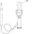
图13是根据图12的框图的MMD的一种形式。该图中,一支表笔13是固定触针的形式。FIG. 13 is a form of MMD according to the block diagram of FIG. 12 . In this figure, a
图14是根据图12的框图的MMD的另一种形式。该图中,图13的固定触针由空速传感器70替代。FIG. 14 is another form of MMD according to the block diagram of FIG. 12 . In this figure, the fixed stylus of FIG. 13 is replaced by an
图15是根据图12的框图的MMD的另一种形式。该图中,图13的固定触针由用于测试电流的夹具80替代。FIG. 15 is another form of MMD according to the block diagram of FIG. 12 . In this figure, the fixed contact pin of Fig. 13 is replaced by a
图16是根据图12的框图的MMD的另一种形式。该图中,图13的固定触针由温度传感器90替代。FIG. 16 is another form of MMD according to the block diagram of FIG. 12 . In this figure, the fixed contact pin of FIG. 13 is replaced by a
图17是根据图12的框图的MMD的另一种形式。该图中,图13的固定触针由气体传感器91替代。FIG. 17 is another form of MMD according to the block diagram of FIG. 12 . In this figure, the fixed contact pin of FIG. 13 is replaced by a
Claims (4)
Translated fromChinesePriority Applications (1)
| Application Number | Priority Date | Filing Date | Title |
|---|---|---|---|
| CN201120003337XUCN202057345U (en) | 2011-01-06 | 2011-01-06 | Measuring and monitoring display |
Applications Claiming Priority (1)
| Application Number | Priority Date | Filing Date | Title |
|---|---|---|---|
| CN201120003337XUCN202057345U (en) | 2011-01-06 | 2011-01-06 | Measuring and monitoring display |
Publications (1)
| Publication Number | Publication Date |
|---|---|
| CN202057345Utrue CN202057345U (en) | 2011-11-30 |
Family
ID=45017316
Family Applications (1)
| Application Number | Title | Priority Date | Filing Date |
|---|---|---|---|
| CN201120003337XUExpired - Fee RelatedCN202057345U (en) | 2011-01-06 | 2011-01-06 | Measuring and monitoring display |
Country Status (1)
| Country | Link |
|---|---|
| CN (1) | CN202057345U (en) |
Cited By (4)
| Publication number | Priority date | Publication date | Assignee | Title |
|---|---|---|---|---|
| US20170060510A1 (en)* | 2015-08-30 | 2017-03-02 | Gaylord Yu | User Interface Based on Device-State Information |
| US20170255434A1 (en)* | 2015-08-30 | 2017-09-07 | EVA Automation, Inc. | User Interface Based on Device-State Information |
| US20170255435A1 (en)* | 2015-08-30 | 2017-09-07 | EVA Automation, Inc. | User Interface Based on Device-State Information |
| US20170255436A1 (en)* | 2015-08-30 | 2017-09-07 | EVA Automation, Inc. | User Interface Based on System-State Information |
- 2011
- 2011-01-06CNCN201120003337XUpatent/CN202057345U/ennot_activeExpired - Fee Related
Cited By (10)
| Publication number | Priority date | Publication date | Assignee | Title |
|---|---|---|---|---|
| US20170060510A1 (en)* | 2015-08-30 | 2017-03-02 | Gaylord Yu | User Interface Based on Device-State Information |
| US20170255434A1 (en)* | 2015-08-30 | 2017-09-07 | EVA Automation, Inc. | User Interface Based on Device-State Information |
| US20170255435A1 (en)* | 2015-08-30 | 2017-09-07 | EVA Automation, Inc. | User Interface Based on Device-State Information |
| US20170255436A1 (en)* | 2015-08-30 | 2017-09-07 | EVA Automation, Inc. | User Interface Based on System-State Information |
| US20170262021A1 (en)* | 2015-08-30 | 2017-09-14 | EVA Automation, Inc. | User Interface Based on Device-State Information |
| US10387094B2 (en)* | 2015-08-30 | 2019-08-20 | EVA Automation, Inc. | User interface based on device-state information |
| US10390080B2 (en)* | 2015-08-30 | 2019-08-20 | EVA Automation, Inc. | User interface based on device-state information |
| US10448091B2 (en)* | 2015-08-30 | 2019-10-15 | EVA Automation, Inc. | User interface based on device-state information |
| US10452332B2 (en)* | 2015-08-30 | 2019-10-22 | EVA Automation, Inc. | User interface based on device-state information |
| US10521177B2 (en)* | 2015-08-30 | 2019-12-31 | EVA Automation, Inc. | User interface based on system-state information |
Similar Documents
| Publication | Publication Date | Title |
|---|---|---|
| US10073668B2 (en) | Method for measuring angles between displays and electronic device using the same | |
| US20250240610A1 (en) | Mobile information terminal, information presentation system and information presentation method | |
| US9551597B2 (en) | Measurement system with image capture capabilities | |
| WO2013119366A1 (en) | Method for managing screen orientation of a portable electronic device | |
| CN202057345U (en) | Measuring and monitoring display | |
| CN108351201A (en) | Object detection device and object detection method | |
| US10816808B2 (en) | Head-mounted display apparatus, information processing device, system, and method for controlling use of captured images from head-mounted display apparatus | |
| CN105674897B (en) | Measure the method and device of object height | |
| CN112256320A (en) | Version number generation method, device, terminal and storage medium | |
| CN113467663A (en) | Interface configuration method and device, computer equipment and medium | |
| CN110765182A (en) | Data statistical method and device, electronic equipment and storage medium | |
| CN107431752B (en) | Processing method and portable electronic equipment | |
| JP2004120223A (en) | Photographing system | |
| CN110673214B (en) | Method and device for predicting depths of inlet target point and end point of horizontal well | |
| CN112529871A (en) | Method and device for evaluating image and computer storage medium | |
| CN201986025U (en) | Telescopic multifunctional camera | |
| CN201854354U (en) | Multi-measure monitoring camera | |
| JP5896018B2 (en) | Photometric device and measurement control program | |
| CN108761033B (en) | Method and device for determining total content of shale loss gas and storage medium | |
| CN114046768B (en) | Laser ranging method, device, laser ranging equipment and storage medium | |
| CN110008671B (en) | Data verification method and device | |
| CN110569064A (en) | interface identifier generation method, device, equipment and storage medium | |
| CN113342645B (en) | Method, device, equipment and storage medium for testing business function | |
| CN104296663B (en) | Object size measuring system and method thereof | |
| CN114706741A (en) | Performance test method, performance test device, computer equipment and medium |
Legal Events
| Date | Code | Title | Description |
|---|---|---|---|
| C14 | Grant of patent or utility model | ||
| GR01 | Patent grant | ||
| CF01 | Termination of patent right due to non-payment of annual fee | Granted publication date:20111130 Termination date:20180106 | |
| CF01 | Termination of patent right due to non-payment of annual fee |