CN202004219U - Electric connector and electric connector terminal - Google Patents
Electric connector and electric connector terminalDownload PDFInfo
- Publication number
- CN202004219U CN202004219UCN2010206773797UCN201020677379UCN202004219UCN 202004219 UCN202004219 UCN 202004219UCN 2010206773797 UCN2010206773797 UCN 2010206773797UCN 201020677379 UCN201020677379 UCN 201020677379UCN 202004219 UCN202004219 UCN 202004219U
- Authority
- CN
- China
- Prior art keywords
- electrical connector
- main body
- terminal
- edge
- insulator
- Prior art date
- Legal status (The legal status is an assumption and is not a legal conclusion. Google has not performed a legal analysis and makes no representation as to the accuracy of the status listed.)
- Expired - Fee Related
Links
Images


Classifications
- H—ELECTRICITY
- H01—ELECTRIC ELEMENTS
- H01R—ELECTRICALLY-CONDUCTIVE CONNECTIONS; STRUCTURAL ASSOCIATIONS OF A PLURALITY OF MUTUALLY-INSULATED ELECTRICAL CONNECTING ELEMENTS; COUPLING DEVICES; CURRENT COLLECTORS
- H01R13/00—Details of coupling devices of the kinds covered by groups H01R12/70 or H01R24/00 - H01R33/00
- H01R13/02—Contact members
- H01R13/10—Sockets for co-operation with pins or blades
- H01R13/11—Resilient sockets
- H—ELECTRICITY
- H01—ELECTRIC ELEMENTS
- H01R—ELECTRICALLY-CONDUCTIVE CONNECTIONS; STRUCTURAL ASSOCIATIONS OF A PLURALITY OF MUTUALLY-INSULATED ELECTRICAL CONNECTING ELEMENTS; COUPLING DEVICES; CURRENT COLLECTORS
- H01R24/00—Two-part coupling devices, or either of their cooperating parts, characterised by their overall structure
- H01R24/38—Two-part coupling devices, or either of their cooperating parts, characterised by their overall structure having concentrically or coaxially arranged contacts
- H01R24/40—Two-part coupling devices, or either of their cooperating parts, characterised by their overall structure having concentrically or coaxially arranged contacts specially adapted for high frequency
- H—ELECTRICITY
- H01—ELECTRIC ELEMENTS
- H01R—ELECTRICALLY-CONDUCTIVE CONNECTIONS; STRUCTURAL ASSOCIATIONS OF A PLURALITY OF MUTUALLY-INSULATED ELECTRICAL CONNECTING ELEMENTS; COUPLING DEVICES; CURRENT COLLECTORS
- H01R43/00—Apparatus or processes specially adapted for manufacturing, assembling, maintaining, or repairing of line connectors or current collectors or for joining electric conductors
- H01R43/16—Apparatus or processes specially adapted for manufacturing, assembling, maintaining, or repairing of line connectors or current collectors or for joining electric conductors for manufacturing contact members, e.g. by punching and by bending
Landscapes
- Connector Housings Or Holding Contact Members (AREA)
Abstract
Translated fromChinese
Description
Translated fromChinese【技术领域】【Technical field】
本实用新型涉及一种电连接器端子及具有所述电连接器端子的电连接器,尤其是关于该电连接器端子边缘的配合结构。The utility model relates to an electrical connector terminal and an electrical connector with the electrical connector terminal, in particular to a matching structure of the edge of the electrical connector terminal.
【背景技术】【Background technique】
台湾专利公告第M340583揭示一种电连接器,该电连接器为射频连接器,其包括一电连接器端子,该电连接器端子设有主体部,主体部由具有相反的第一边缘和第二边缘的料带冲压卷折而成,第一边缘和第二边缘靠拢设置但不连接,即第一边缘和第二边缘无配合即有间隙。所述电连接器端子因第一边缘与第二边缘因卷曲相互靠拢形成封闭的筒状侧壁,所述筒状侧臂围成一中空的空腔,所述侧壁被冲切形成接触臂,所述接触臂的末端延伸入空腔以与一对接连接器之柱状端子接触配合。但是,由于电连接器端子的第一边缘和第二边缘靠拢不连接,对接连接器端子多次插拔后,由于对接连接器端子对连接器端子接触臂产生的正向力,通过接触臂传送给侧壁,导致第一边缘和第二边缘之间的间隙变大,使得接触臂的末端对对接连接器端子的夹持力变小而最终导致接触失效。因此,需要对现有技术进行改进以满足电连接器端子在多次插拔后能够保持较好的保持力。Taiwan Patent Publication No. M340583 discloses an electrical connector, the electrical connector is a radio frequency connector, which includes an electrical connector terminal, the electrical connector terminal is provided with a main body, the main body has opposite first edges and second The material strips at the two edges are punched and folded, and the first edge and the second edge are set close to each other but not connected, that is, there is a gap between the first edge and the second edge without cooperation. The first edge and the second edge of the electrical connector terminal close together to form a closed cylindrical side wall due to curling, and the cylindrical side arm encloses a hollow cavity, and the side wall is punched to form a contact arm , the end of the contact arm extends into the cavity so as to contact and fit with the columnar terminal of a mating connector. However, since the first edge and the second edge of the electrical connector terminal are close together and are not connected, after the butt connector terminal is plugged and pulled out for many times, due to the positive force generated by the butt connector terminal to the contact arm of the connector terminal, the force transmitted through the contact arm For the side wall, the gap between the first edge and the second edge becomes larger, so that the clamping force of the end of the contact arm on the terminal of the mating connector becomes smaller, which eventually leads to contact failure. Therefore, it is necessary to improve the prior art so that the terminals of the electrical connector can maintain a better holding force after multiple insertions and extractions.
【实用新型内容】【Content of utility model】
本实用新型的目的在于提供一种电连接器端子,该电连接器端子在与对接连接器配合时具有较好的接触保持力。The purpose of the utility model is to provide an electrical connector terminal, which has better contact holding force when mated with a butt connector.
为解决上述问题,本实用新型提供一种电连接器端子,其设有主体部,所述主体部由具有相反的第一边缘与第二边缘的料带卷曲形成,所述第一边缘与第二边缘因卷曲相互靠拢形成封闭的筒状侧壁,且所述侧壁被冲切形成向内凸伸的接触臂,主体部上端形成开口,可供一对接连接器之柱状端子插入主体部内,进而与接触臂接触配合,所述第一边缘处于右侧并设有向右侧凹陷的槽口,所述第二边缘处于左侧并设有向右侧凸伸嵌入槽口的凸片。In order to solve the above problems, the utility model provides an electrical connector terminal, which is provided with a main body, and the main body is formed by crimping a material strip with opposite first and second edges, and the first and second edges are The two edges are curled together to form a closed cylindrical side wall, and the side wall is punched to form an inwardly protruding contact arm, and an opening is formed at the upper end of the main body, which can be inserted into the main body by a cylindrical terminal of a mating connector. Further, it is in contact with the contact arm, the first edge is on the right side and is provided with a notch recessed to the right side, and the second edge is on the left side and is provided with a tab protruding to the right side and embedded in the notch.
本实用新型的目的在于提供一种电连接器,所述电连接器之电连接器端子在与对接连接器配合时具有较好的接触保持力。The purpose of the utility model is to provide an electrical connector, the electrical connector terminal of the electrical connector has better contact holding force when mated with a butt connector.
为解决上述问题,本实用新型提供一种电连接器,其包括设有收容空间的外导体、收容于外导体内的绝缘体及收容于绝缘体内的电连接器端子,所述电连接器端子设有主体部,所述主体部由具有相反的第一边缘与第二边缘的料带卷曲形成,所述第一边缘与第二边缘因卷曲相互靠拢形成封闭的筒状侧壁,且所述侧壁被冲切形成向内凸伸的接触臂,主体部上端形成开口,可供一对接连接器之柱状端子插入主体部内,进而与接触臂接触配合,所述第一边缘处于右侧并设有向右侧凹陷的槽口,所述第二边缘处于左侧并设有向右侧凸伸嵌入槽口的凸片。In order to solve the above problems, the utility model provides an electrical connector, which includes an outer conductor with a receiving space, an insulator accommodated in the outer conductor, and an electrical connector terminal accommodated in the insulator. There is a main body part, and the main body part is formed by curling a strip having opposite first and second edges, and the first edge and the second edge are closed to each other due to curling to form a closed cylindrical side wall, and the side wall The wall is punched to form an inwardly protruding contact arm, and an opening is formed at the upper end of the main body, allowing the columnar terminal of a mating connector to be inserted into the main body, and then to contact and cooperate with the contact arm. The first edge is on the right side and has a The notch is recessed to the right, and the second edge is on the left side and is provided with a tab protruding to the right and embedded in the notch.
相对于现有技术,本实用新型之电连接器端子在料带卷曲成型时,通过将成型的料带之第一边缘和第二边缘设置相互配合之槽口和凸片,使得第一边缘和第二边缘通过槽口和凸片的扣合而稳定配合在一起,结构稳定,对接连接器的对接端子插入后,对接端子对接触臂产生的正压力传送至其配合位置时,第一边缘和第二边缘的配合稳定,不会分离,从而使得电连接器端子与对接连接器配合时具有较好的接触保持力。Compared with the prior art, when the electrical connector terminal of the present invention is crimped and formed, the first edge and the second edge of the formed material strip are provided with notches and protruding pieces that cooperate with each other, so that the first edge and the second edge The second edge is stably fitted together through the fastening of the notch and the tab, and the structure is stable. After the butt terminal of the butt connector is inserted, when the positive pressure generated by the butt terminal on the contact arm is transmitted to its mating position, the first edge and The mating of the second edge is stable and will not be separated, so that the electrical connector terminal has better contact holding force when mated with the butt connector.
【附图说明】【Description of drawings】
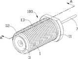
图1为符合本实用新型的电连接器的组装立体图;Fig. 1 is an assembled perspective view of an electrical connector according to the present invention;
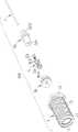
图2为图1所示电连接器的分解图;Fig. 2 is an exploded view of the electrical connector shown in Fig. 1;
图3为图2所示电连接器的电连接器端子的立体图;Fig. 3 is a perspective view of an electrical connector terminal of the electrical connector shown in Fig. 2;
图4为图1所示电连接器沿A-A方向的剖视图。FIG. 4 is a cross-sectional view along the direction A-A of the electrical connector shown in FIG. 1 .
【主要元件符号说明】[Description of main component symbols]
电连接器 100 外导体 1
绝缘体 3 电连接器端子 5
中心端子 7 收容空间 10Center Terminal 7 Containment Space 10
安装端 11 配合端 12
螺纹 13 第一绝缘体 31
第二绝缘体 32 主体部 51
连接部 53 大直径部 101Connecting
小直径部 102 凸缘 103
前端孔 321 后端孔 322
凸肋 323 第一边缘 511Convex Rib 323 First Edge 511
第二边缘 512 筒状侧壁 513
第一侧壁 513a 第二侧壁 513b
第三侧壁 513c 第四侧壁 513d
对接空间 514 接触臂 515
上端 516 开口 517
槽口 518 凸片 519Notch 518
凸块 520 侧臂 521Lug 520 Sidearm 521
卡臂 522 收容孔 531Arm 522 Storage Hole 531
【具体实施方式】【Detailed ways】
请参阅图1至4所示为符合本实用新型的电连接器100,其包括设有收容空间10的外导体1、收容于外导体1内的绝缘体3及收容于绝缘体3内的电连接器端子5、中心端子7。1 to 4 show an
请参阅图2,所述外导体1呈前后延伸的圆柱体,其具有安装至一外部设备的安装端11及与对接连接器(未图示)配合连接的配合端12,所述配合端12在其外侧面设有与对接连接器(未图示)配合的螺纹13。所述收容空间10沿圆柱体中轴线贯穿外导体1的两端,该收容空间10包括大直径部101及小直径部102,所述大、小直径部101、102前后贯通,且小直径部102靠近外导体1的后端向收容空间10内设有凸缘103。Please refer to Fig. 2, the
所述绝缘体3包括安装至外导体1之配合端12的第一绝缘体31及安装至安装端11的第二绝缘体32。所述第一绝缘体31用于将电连接器端子5固定于外导体1的收容空间10内,该第一绝缘体31呈圆柱状,其设有收容电连接器端子5的方形孔(未图示)。所述第二绝缘体32呈圆柱状,且该第二绝缘体32沿其中心轴线依次设有收容部分电连接器端子5的前端孔321和收容中心端子7的后端孔322,所述前端孔321和后端孔322前后贯通。前端孔321用于收容电连接器端子5,而后端孔322则用于收容中心端子7。所述第二绝缘体32在其外表面涂设有一凸肋323,所述凸肋323与外导体1的凸缘103配合将第二绝缘体32及中心端子7稳定收容在外导体1的小直径部102。The
请参阅图2和图3所示,电连接器端子5设有主体部51及连接于主体部51的连接部53,所述主体部51由具有相反的第一边缘511与第二边缘512的料带卷曲形成,所述第一边缘511与第二边缘512因卷曲相互靠拢形成封闭的筒状侧壁513,所述筒状侧壁513具有相互连接的四个侧壁,其中第一至第三侧壁513a-513c为完整的料带卷曲形成,第四侧壁513d则由设有第一边缘511和设有第二边缘512的部分料带连接而成,所述四个侧壁围设形成可供一对接连接器(未图示)之柱状端子插入的对接空间514。所述第二侧壁513b和第四侧壁513d平行相对设置,第一侧壁513a和第三侧壁513c亦平行相对设置且分别连接第二侧壁513b和第四侧壁513d而形成完整的筒状侧壁513。所述第一侧壁513a和第三侧壁513c被冲切形成向内即向对接空间514凸伸的接触臂515。2 and 3, the
主体部51设有上端516,该上端516形成开口517,该开口517可供一对接连接器(未图示)之柱状端子插入主体部51内,进而与接触臂515接触配合,所述第一边缘511处于右侧并设有向右侧凹陷的槽口518,所述第二边缘处512于左侧并设有向右侧凸伸嵌入槽口518的凸片519。所述凸片519的上侧向上延伸形成凸块520,槽口518的上侧形成向左延伸的侧臂521,侧臂521的延伸末端向下延伸形成卡臂522,所述卡臂522可抵靠于凸块520的右侧,且所述槽口518与凸片519最后通过铆压连接。所述连接部53自主体部51下端延伸形成,连接部53设有收容中心端子7的收容孔531。所述主体部51呈方形柱状设置,该主体部51收容在第一绝缘体31的方形孔内,连接部53收容在第二绝缘体32的前端孔321内。所述主体部51的方形形状与第一绝缘体31的方形孔相互配合将电连接器端子5固定在第一绝缘体31内,且方形的结构能够防止电连接器端子5在第一绝缘体31内绕轴向转动。The
电连接器端子5在料带卷曲成型时,通过将成型的料带之第一边缘511和第二边缘512设置相互配合之槽口518和凸片519,使得第一边缘511和第二边缘512通过槽口518和凸片519的扣合而稳定配合在一起,结构稳定,对接连接器的对接端子插入后,对接端子对接触臂515产生的正压力传送至其配合位置时,第一边缘511和第二边缘512的配合稳定,不会分离,从而使得电连接器端子5与对接连接器配合时具有较好的接触保持力。When the
中心端子7为一直的圆柱形端子,该中心端子7的一端收容在电连接器端子5的连接部53的收容孔531内,并与电连接器端子5的连接部53固定收容在第二绝缘体32的前端孔321内,中间部分则收容在第二绝缘体32的后端孔322内,部分则延伸出外导体1用于连接至一外部电路板或其它设备(未图示)。The central terminal 7 is a straight cylindrical terminal, and one end of the central terminal 7 is accommodated in the receiving
Claims (7)
Translated fromChinesePriority Applications (2)
| Application Number | Priority Date | Filing Date | Title |
|---|---|---|---|
| CN2010206773797UCN202004219U (en) | 2010-12-23 | 2010-12-23 | Electric connector and electric connector terminal |
| US13/336,456US8454395B2 (en) | 2010-12-23 | 2011-12-23 | Electrical connector having improved contact member |
Applications Claiming Priority (1)
| Application Number | Priority Date | Filing Date | Title |
|---|---|---|---|
| CN2010206773797UCN202004219U (en) | 2010-12-23 | 2010-12-23 | Electric connector and electric connector terminal |
Publications (1)
| Publication Number | Publication Date |
|---|---|
| CN202004219Utrue CN202004219U (en) | 2011-10-05 |
Family
ID=44706946
Family Applications (1)
| Application Number | Title | Priority Date | Filing Date |
|---|---|---|---|
| CN2010206773797UExpired - Fee RelatedCN202004219U (en) | 2010-12-23 | 2010-12-23 | Electric connector and electric connector terminal |
Country Status (2)
| Country | Link |
|---|---|
| US (1) | US8454395B2 (en) |
| CN (1) | CN202004219U (en) |
Cited By (2)
| Publication number | Priority date | Publication date | Assignee | Title |
|---|---|---|---|---|
| CN108123248A (en)* | 2016-11-30 | 2018-06-05 | 李尔公司 | Female electric terminal |
| CN110829105A (en)* | 2019-10-30 | 2020-02-21 | 广东林一新能源科技有限公司 | A waterproof structure for interlocking terminals |
Families Citing this family (11)
| Publication number | Priority date | Publication date | Assignee | Title |
|---|---|---|---|---|
| US8758050B2 (en)* | 2011-06-10 | 2014-06-24 | Hiscock & Barclay LLP | Connector having a coupling member for locking onto a port and maintaining electrical continuity |
| US9004931B2 (en) | 2011-06-10 | 2015-04-14 | Ppc Broadband, Inc. | Coaxial interface port accessory and port facilitating slide-on attachment and rotational detachment of cable connectors |
| US9178317B2 (en)* | 2012-04-04 | 2015-11-03 | Holland Electronics, Llc | Coaxial connector with ingress reduction shield |
| US9246275B2 (en)* | 2012-04-04 | 2016-01-26 | Holland Electronics, Llc | Coaxial connector with ingress reduction shielding |
| US9960542B2 (en) | 2012-04-04 | 2018-05-01 | Holland Electronics, Llc | Coaxial connector with ingress reduction shielding |
| US9711919B2 (en) | 2012-04-04 | 2017-07-18 | Holland Electronics, Llc | Coaxial connector with ingress reduction shielding |
| US10630032B2 (en) | 2012-04-04 | 2020-04-21 | Holland Electronics, Llc | Coaxial connector with ingress reduction shielding |
| JP5367121B2 (en)* | 2012-05-09 | 2013-12-11 | 日本航空電子工業株式会社 | connector |
| US9106035B2 (en) | 2012-06-25 | 2015-08-11 | Dish Network L.L.C. | RF connector with push-on connection |
| US9762007B2 (en)* | 2016-02-10 | 2017-09-12 | Dish Network L.L.C. | Push on connector |
| JP7472828B2 (en)* | 2021-03-10 | 2024-04-23 | 住友電装株式会社 | Terminals |
Family Cites Families (16)
| Publication number | Priority date | Publication date | Assignee | Title |
|---|---|---|---|---|
| US2704357A (en)* | 1952-11-14 | 1955-03-15 | Johnson Co E F | Electrical jack |
| US3054083A (en)* | 1957-09-24 | 1962-09-11 | Aymar Julian Robert | Electrical contact devices |
| US3525973A (en)* | 1968-06-17 | 1970-08-25 | Hyman J Kipnes | Electrical connectors |
| US3611271A (en)* | 1969-04-07 | 1971-10-05 | Gold Line Connector Inc | Connector for coaxial transmission lines |
| US3678444A (en)* | 1971-01-15 | 1972-07-18 | Bendix Corp | Connector with isolated ground |
| US4035045A (en)* | 1974-01-24 | 1977-07-12 | Daniel Woodhead, Inc. | Grounding jack |
| US5033982A (en)* | 1990-05-31 | 1991-07-23 | Sun Microstamping, Inc. | Electrical connector |
| US5011440A (en)* | 1990-09-10 | 1991-04-30 | Lee Chun Te | Wire connector |
| US5971770A (en)* | 1997-11-05 | 1999-10-26 | Labinal Components And Systems, Inc. | Coaxial connector with bellows spring portion or raised bump |
| US5980326A (en)* | 1998-06-04 | 1999-11-09 | The Whitaker Corporation | Sealed bulkhead coaxial jack and related method |
| JP3678145B2 (en)* | 2000-12-22 | 2005-08-03 | 住友電装株式会社 | connector |
| US7553187B2 (en)* | 2006-01-31 | 2009-06-30 | 3M Innovative Properties Company | Electrical connector assembly |
| JP2007280850A (en)* | 2006-04-10 | 2007-10-25 | Sumitomo Wiring Syst Ltd | Terminal metal fitting |
| US7510436B2 (en)* | 2007-06-01 | 2009-03-31 | Ftime Technology Industrial Co., Ltd. | Multi-connector set for signal testing |
| CN201142405Y (en) | 2007-12-11 | 2008-10-29 | 富士康(昆山)电脑接插件有限公司 | electrical connector |
| US8172617B2 (en)* | 2010-04-02 | 2012-05-08 | F Time Technology Industrial Co., Ltd. | RF connector |
- 2010
- 2010-12-23CNCN2010206773797Upatent/CN202004219U/ennot_activeExpired - Fee Related
- 2011
- 2011-12-23USUS13/336,456patent/US8454395B2/ennot_activeExpired - Fee Related
Cited By (2)
| Publication number | Priority date | Publication date | Assignee | Title |
|---|---|---|---|---|
| CN108123248A (en)* | 2016-11-30 | 2018-06-05 | 李尔公司 | Female electric terminal |
| CN110829105A (en)* | 2019-10-30 | 2020-02-21 | 广东林一新能源科技有限公司 | A waterproof structure for interlocking terminals |
Also Published As
| Publication number | Publication date |
|---|---|
| US8454395B2 (en) | 2013-06-04 |
| US20120164862A1 (en) | 2012-06-28 |
Similar Documents
| Publication | Publication Date | Title |
|---|---|---|
| CN202004219U (en) | Electric connector and electric connector terminal | |
| JP5766848B1 (en) | connector | |
| US8851920B2 (en) | Plug-in wire connection terminal structure | |
| US7717755B2 (en) | Electrical connector with improved contacts | |
| WO2015025571A1 (en) | Coaxial connector and connecting part | |
| US8562374B2 (en) | Harness connector | |
| WO2014038617A1 (en) | Terminal | |
| US8491332B1 (en) | Slim C5/C6 coupler | |
| US7604518B2 (en) | Electrical contact with retention latch | |
| CN202749625U (en) | Improved structure of audio-video connector | |
| US10811803B2 (en) | Connection terminal | |
| JP2013118102A (en) | Female terminal structure | |
| CN204966724U (en) | IDC male connector | |
| JP6681655B2 (en) | Coaxial connector | |
| CN209804966U (en) | Straight connector jack | |
| CN201741875U (en) | Socket conducting strip and power adapter with same | |
| CN202167642U (en) | electrical connector | |
| CN223109264U (en) | Stamping terminals, high voltage connector contacts and high voltage connectors | |
| CN204905510U (en) | Wire end connector | |
| TWI253785B (en) | Power connector | |
| US20240162631A1 (en) | Connector Terminal, Connector Housing and Connector | |
| CN201594646U (en) | electrical connector | |
| CN208444974U (en) | Electric connector | |
| US20130078863A1 (en) | Electrical connector | |
| WO2015099180A1 (en) | Connector |
Legal Events
| Date | Code | Title | Description |
|---|---|---|---|
| C14 | Grant of patent or utility model | ||
| GR01 | Patent grant | ||
| CF01 | Termination of patent right due to non-payment of annual fee | ||
| CF01 | Termination of patent right due to non-payment of annual fee | Granted publication date:20111005 Termination date:20171223 |