CN202004179U - Electric connector - Google Patents
Electric connectorDownload PDFInfo
- Publication number
- CN202004179U CN202004179UCN2010206437743UCN201020643774UCN202004179UCN 202004179 UCN202004179 UCN 202004179UCN 2010206437743 UCN2010206437743 UCN 2010206437743UCN 201020643774 UCN201020643774 UCN 201020643774UCN 202004179 UCN202004179 UCN 202004179U
- Authority
- CN
- China
- Prior art keywords
- electric connector
- insulating body
- conducting terminal
- installation portion
- locating piece
- Prior art date
- Legal status (The legal status is an assumption and is not a legal conclusion. Google has not performed a legal analysis and makes no representation as to the accuracy of the status listed.)
- Expired - Fee Related
Links
Images


Landscapes
- Multi-Conductor Connections (AREA)
- Coupling Device And Connection With Printed Circuit (AREA)
Abstract
Description
Translated fromChinese【技术领域】【Technical field】
本实用新型涉及一种电连接器,尤其是指一种用以表面安装于电路板上的电连接器。The utility model relates to an electric connector, in particular to an electric connector used for surface mounting on a circuit board.
【背景技术】【Background technique】
电连接器及电连接器组件在通信领域应用非常广泛,常焊接于电路板上。电连接器与电路板的连接方法分为表面安装方式和通孔焊接两种。目前随着笔记本电脑的蓬勃发展,表面安装技术(SMT)日益得到广泛运用,为了保证端子共面度,提升产品自动化制造能力迫在眉睫。Electrical connectors and electrical connector components are widely used in the communication field, and are often soldered on circuit boards. The connection method between the electrical connector and the circuit board is divided into two types: surface mounting method and through-hole welding. At present, with the vigorous development of notebook computers, surface mount technology (SMT) is increasingly widely used. In order to ensure the coplanarity of terminals, it is imminent to improve the automatic manufacturing capabilities of products.
与本实用新型电连接器相关的现有技术可参阅2002年4月9日公告的第6,042,420号美国专利。该专利揭示了一种电连接器,包括绝缘本体及收容于绝缘本体内的导电端子。绝缘本体设有相对设置的对接壁和底壁,对接壁向内凹设有有一定深度的收容腔。导电端子包括延伸入收容腔的接触部、用于表面安装于电路板上的安装部及连接安装部与接触部的连接部。其中安装部自连接部水平延伸超出后壁。如此设置,若导电端子的安装部较长,很难保证安装部的共面度。从而,导电端子的安装部通过表面安装技术(SMT)焊接于电路板时,可能由于安装部的共面度不够,而造成虚焊。For the prior art related to the electrical connector of the present invention, please refer to US Patent No. 6,042,420 published on April 9, 2002. This patent discloses an electrical connector, which includes an insulating body and conductive terminals accommodated in the insulating body. The insulating body is provided with a butt wall and a bottom wall which are oppositely arranged, and the abutment wall is concavely provided with a receiving cavity with a certain depth. The conductive terminal includes a contact portion extending into the receiving cavity, a mounting portion for surface mounting on a circuit board, and a connecting portion connecting the mounting portion and the contact portion. Wherein the installation part extends horizontally from the connection part beyond the rear wall. In such an arrangement, if the mounting portion of the conductive terminal is long, it is difficult to ensure the coplanarity of the mounting portion. Therefore, when the mounting portion of the conductive terminal is soldered to the circuit board by surface mount technology (SMT), the coplanarity of the mounting portion may be insufficient, resulting in false soldering.
【实用新型内容】【Content of utility model】
本实用新型要解决的技术问题是:提供一种可保持导电端子的安装部高共面度的电连接器。The technical problem to be solved by the utility model is to provide an electrical connector capable of maintaining high coplanarity of the installation part of the conductive terminal.
为了解决上述问题,本实用新型提供一种电连接器,其包括绝缘本体及若干导电端子,所述导电端子设有用于固定于绝缘本体内的固定部及自固定部弯折延伸出的安装部,安装部用于表面安装于电路板上,所述电连接器还包括安装于绝缘本体且抵压安装部的定位块,所述安装部受定位块抵压而处于同一平面上。In order to solve the above problems, the utility model provides an electrical connector, which includes an insulating body and a plurality of conductive terminals, and the conductive terminals are provided with a fixing part for fixing in the insulating body and a mounting part bent and extended from the fixing part The mounting part is used for surface mounting on the circuit board, and the electrical connector further includes a positioning block mounted on the insulating body and pressing against the mounting part, and the mounting part is pressed by the positioning block to be on the same plane.
与现有技术相比,本实用新型的电连接器通过在绝缘本体上安装定位块,定位块对导电端子的安装部重新定位,从而确保安装部的高共面度。Compared with the prior art, the electrical connector of the utility model installs the positioning block on the insulating body, and the positioning block repositions the mounting portion of the conductive terminal, thereby ensuring high coplanarity of the mounting portion.
【附图说明】【Description of drawings】
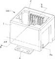
图1是本实用新型电连接器的立体图。Fig. 1 is a perspective view of the electrical connector of the present invention.
图2是图1所示电连接器的另一视角的立体图。FIG. 2 is a perspective view from another perspective of the electrical connector shown in FIG. 1 .
图3是图1所示电连接器的爆炸图。FIG. 3 is an exploded view of the electrical connector shown in FIG. 1 .
图4是图1所示电连接器的另一视角的爆炸图。FIG. 4 is an exploded view from another perspective of the electrical connector shown in FIG. 1 .
图5是图1所示电连接器的部分拆解图。FIG. 5 is a partially disassembled view of the electrical connector shown in FIG. 1 .
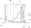
图6是图1所示电连接器沿A-A线的剖视图。FIG. 6 is a cross-sectional view of the electrical connector shown in FIG. 1 along line A-A.
图7是图1所示电连接器沿B-B线的剖视图。FIG. 7 is a cross-sectional view of the electrical connector shown in FIG. 1 along line B-B.
【主要元件符号说明】[Description of main component symbols]
电连接器 100 绝缘本体 1
后壁 11 侧壁 12
对接壁 13 底壁 14
收容腔 15 上凸肋 16
上固定槽 161 下凸肋 17
下固定槽 171 定位槽 18
收容槽 19 导电端子 2
接触部 21 固定部 22Contact
上凸块 221 下凸块 222
安装部 23 定位块 3
主体部 31 主体部顶面 311
底面 312 扣持臂 32Bottom 312 Catch
扣持臂顶面 321 扣钩 33Clasp arm
倒角部 34 固定板 4Chamfering
水平部 41 底孔 411
垂直部 42 扣孔 421
【具体实施方式】【Detailed ways】
请参照图1至图3所示,本实用新型电连接器100,用于表面安装到电路板(未图示)上,其包括绝缘本体1、收容于绝缘本体1内的若干导电端子2、安装于绝缘本体1并抵压导电端子2的定位块3及固定于绝缘本体1的固定板4。Please refer to Figures 1 to 3, the utility model
附图所示为一种可以与对接插头连接器相配合的Modular Jack连接器。然而,本实用新型不止限于Modular Jack连接器,而应该被理解为,包括所有基于本发明定位块抵压导电端子的其他各类电连接器。The attached figure shows a Modular Jack connector that can be mated with a mating plug connector. However, the present invention is not limited to the Modular Jack connector, but should be understood as including all other types of electrical connectors in which the positioning block presses the conductive terminals based on the present invention.
请参照图3至图6所示,绝缘本体1设有用于固定导电端子2的后壁11、两侧壁12、对接壁13、与对接壁13相对设置的底壁14、以及收容腔15,其中收容腔15自对接壁13向内凹陷形成,以供对接连接器插入配合(未图示)。后壁11设有若干凸肋,所述凸肋包括一排上凸肋16及一排下凸肋17,相邻的两个上凸肋16之间形成上固定槽161,相邻的两个下凸肋17之间形成下固定槽171,导电端子2收容于上固定槽161及下固定槽171内。后壁11的底部设有贯穿底壁14的定位槽18,以及向收容腔15方向内陷形成的收容槽19,且定位槽18与收容槽19相贯通。所述收容槽19内部设有向侧壁12外侧凹陷形成的扣持槽191,且扣持槽191贯穿侧壁12(如图6所示)。3 to 6, the
导电端子2设有接触部21、固定部22及自固定部22弯折延伸出的安装部23,其中固定部22位于安装部23与接触部21之间用以电性连接安装部23与接触部21。固定部22设有向外突出的凸块,所述凸块包括上凸块221及下凸块222,上凸块221用以与上凸肋16干涉配合,下凸块222用以与下凸肋17干涉配合。所述接触部21自固定部22弯折延伸入收容腔15内用以与对接连接器(未图示)导电配合。所述安装部23自固定部22向外延伸超出后壁11,用以表面安装于电路板(未图示)上。The
定位块3包括主体部31、自主体部31的顶端垂直于主体部31方向延伸出的两扣持臂32,且两扣持臂32分隔设置于主体部31两端。主体部31设有位于主体部31底部的底面312及与底面312相对设置的主体部顶面311。底面312处于同一水平面上且抵压导电端子2的安装部23。扣持臂32也设有扣持臂顶面321,且扣持臂顶面321高于主体部顶面311。扣持臂32的自由端设有侧向突出形成的扣钩33,且扣钩33成楔形状。扣持臂32设有位于扣钩33前端的倒角部34,设置倒角部34可以导引扣持臂32更轻易地安装到收容槽19内。The
如图6所示,所述扣持臂32收容于前述绝缘本体1的收容槽19内。所述扣钩33扣持于前述绝缘本体1的扣持槽191内。所述主体部31收容于前述绝缘本体1的定位槽18内。如图2和图7所示,定位块3的主体部31与绝缘本体1的下凸肋17相抵压,设置下凸肋17能保证定位块3的安装稳定。所述主体部31的底面312抵压导电端子2的安装部23,以确保安装部23处于同一平面上。As shown in FIG. 6 , the
请参照图3至图4所示,固定板4包括水平部41及与水平部41相垂直的垂直部42。其中水平部41用于表面焊接到电路板(未图示)上,且水平部41与导电端子2的安装部23平齐(如图7所示)。所述水平部41设有两底孔411,以利于水平部41焊接到电路板(未图示)上的散热及焊接均匀。垂直部42设有用于与绝缘本体1相扣合的扣孔421,以确保绝缘本体1更牢固的固定到电路板(未图示)上。Referring to FIGS. 3 to 4 , the fixing
在安装时,首先将导电端子2的接触部21从后壁11插入到绝缘本体1的收容腔15内。然后,将导电端子2的固定部22安装到后壁11的上固定槽161及下固定槽171内,以达成稳定的干涉配合。并将导电端子2的安装部23预弯折,安装部23与固定部22的预弯折角小于90度。最后,将定位块3安装到绝缘本体1上,导电端子2的安装部23受定位块3的底面312抵压回弹而处于同一平面上。以此来保证导电端子2的安装部23的高共面度,并满足表面安装技术的要求。When installing, firstly insert the
Claims (10)
Priority Applications (1)
| Application Number | Priority Date | Filing Date | Title |
|---|---|---|---|
| CN2010206437743UCN202004179U (en) | 2010-12-07 | 2010-12-07 | Electric connector |
Applications Claiming Priority (1)
| Application Number | Priority Date | Filing Date | Title |
|---|---|---|---|
| CN2010206437743UCN202004179U (en) | 2010-12-07 | 2010-12-07 | Electric connector |
Publications (1)
| Publication Number | Publication Date |
|---|---|
| CN202004179Utrue CN202004179U (en) | 2011-10-05 |
Family
ID=44706906
Family Applications (1)
| Application Number | Title | Priority Date | Filing Date |
|---|---|---|---|
| CN2010206437743UExpired - Fee RelatedCN202004179U (en) | 2010-12-07 | 2010-12-07 | Electric connector |
Country Status (1)
| Country | Link |
|---|---|
| CN (1) | CN202004179U (en) |
Cited By (2)
| Publication number | Priority date | Publication date | Assignee | Title |
|---|---|---|---|---|
| CN105449417A (en)* | 2015-08-12 | 2016-03-30 | 凡甲电子(苏州)有限公司 | Electric connector |
| CN111490383A (en)* | 2020-04-10 | 2020-08-04 | 宁波市富来电子科技有限公司 | Structure for improving deformation of contact pin in L ED module of car lamp |
- 2010
- 2010-12-07CNCN2010206437743Upatent/CN202004179U/ennot_activeExpired - Fee Related
Cited By (3)
| Publication number | Priority date | Publication date | Assignee | Title |
|---|---|---|---|---|
| CN105449417A (en)* | 2015-08-12 | 2016-03-30 | 凡甲电子(苏州)有限公司 | Electric connector |
| CN105449417B (en)* | 2015-08-12 | 2017-12-12 | 凡甲电子(苏州)有限公司 | Electric connector |
| CN111490383A (en)* | 2020-04-10 | 2020-08-04 | 宁波市富来电子科技有限公司 | Structure for improving deformation of contact pin in L ED module of car lamp |
Similar Documents
| Publication | Publication Date | Title |
|---|---|---|
| CN201638995U (en) | Connector | |
| CN201060978Y (en) | Board-to-board connector | |
| CN201355730Y (en) | electrical connector | |
| US9853403B1 (en) | Board to board connector assembly, female connector and male connector | |
| CN201355711Y (en) | electrical connector | |
| CN201112846Y (en) | electrical connector | |
| CN202004179U (en) | Electric connector | |
| CN100429832C (en) | Electrical Connector Assembly | |
| CN2809973Y (en) | Power supply connector | |
| CN101997212A (en) | Electric connector | |
| CN201562777U (en) | Electric connector with locking mechanism | |
| CN201430229Y (en) | Electric connector | |
| CN111628317B (en) | A board-to-board connector | |
| CN201285955Y (en) | Electric connector | |
| CN201639027U (en) | Electric connector | |
| CN201690033U (en) | electrical connector | |
| CN201498653U (en) | Electrical connector | |
| CN2850024Y (en) | Electric connector | |
| CN216289300U (en) | Electric connector | |
| CN202602014U (en) | Metal housing of electrical connector, electrical connector and assembly of electrical connector and circuit board | |
| CN201112619Y (en) | electrical connector | |
| CN201608387U (en) | Pick and place device and electrical connector assembly | |
| CN201667429U (en) | Electric connector | |
| CN201927736U (en) | Electric connector | |
| CN201352618Y (en) | Board-to-Board Connector |
Legal Events
| Date | Code | Title | Description |
|---|---|---|---|
| C14 | Grant of patent or utility model | ||
| GR01 | Patent grant | ||
| C17 | Cessation of patent right | ||
| CF01 | Termination of patent right due to non-payment of annual fee | Granted publication date:20111005 Termination date:20111207 |