CN202004173U - Sinking plate connector - Google Patents
Sinking plate connectorDownload PDFInfo
- Publication number
- CN202004173U CN202004173UCN2010206476061UCN201020647606UCN202004173UCN 202004173 UCN202004173 UCN 202004173UCN 2010206476061 UCN2010206476061 UCN 2010206476061UCN 201020647606 UCN201020647606 UCN 201020647606UCN 202004173 UCN202004173 UCN 202004173U
- Authority
- CN
- China
- Prior art keywords
- extendible flake
- type connector
- sidewall
- plate type
- extending
- Prior art date
- Legal status (The legal status is an assumption and is not a legal conclusion. Google has not performed a legal analysis and makes no representation as to the accuracy of the status listed.)
- Expired - Lifetime
Links
Images


Classifications
- H—ELECTRICITY
- H01—ELECTRIC ELEMENTS
- H01R—ELECTRICALLY-CONDUCTIVE CONNECTIONS; STRUCTURAL ASSOCIATIONS OF A PLURALITY OF MUTUALLY-INSULATED ELECTRICAL CONNECTING ELEMENTS; COUPLING DEVICES; CURRENT COLLECTORS
- H01R12/00—Structural associations of a plurality of mutually-insulated electrical connecting elements, specially adapted for printed circuits, e.g. printed circuit boards [PCB], flat or ribbon cables, or like generally planar structures, e.g. terminal strips, terminal blocks; Coupling devices specially adapted for printed circuits, flat or ribbon cables, or like generally planar structures; Terminals specially adapted for contact with, or insertion into, printed circuits, flat or ribbon cables, or like generally planar structures
- H01R12/70—Coupling devices
- H01R12/7005—Guiding, mounting, polarizing or locking means; Extractors
- H01R12/7011—Locking or fixing a connector to a PCB
- H01R12/7052—Locking or fixing a connector to a PCB characterised by the locating members
- G—PHYSICS
- G02—OPTICS
- G02B—OPTICAL ELEMENTS, SYSTEMS OR APPARATUS
- G02B6/00—Light guides; Structural details of arrangements comprising light guides and other optical elements, e.g. couplings
- G02B6/24—Coupling light guides
- G02B6/36—Mechanical coupling means
- G02B6/38—Mechanical coupling means having fibre to fibre mating means
- G02B6/3807—Dismountable connectors, i.e. comprising plugs
- G02B6/381—Dismountable connectors, i.e. comprising plugs of the ferrule type, e.g. fibre ends embedded in ferrules, connecting a pair of fibres
- G02B6/3817—Dismountable connectors, i.e. comprising plugs of the ferrule type, e.g. fibre ends embedded in ferrules, connecting a pair of fibres containing optical and electrical conductors
- G—PHYSICS
- G02—OPTICS
- G02B—OPTICAL ELEMENTS, SYSTEMS OR APPARATUS
- G02B6/00—Light guides; Structural details of arrangements comprising light guides and other optical elements, e.g. couplings
- G02B6/24—Coupling light guides
- G02B6/42—Coupling light guides with opto-electronic elements
- G02B6/4292—Coupling light guides with opto-electronic elements the light guide being disconnectable from the opto-electronic element, e.g. mutually self aligning arrangements
- H—ELECTRICITY
- H01—ELECTRIC ELEMENTS
- H01R—ELECTRICALLY-CONDUCTIVE CONNECTIONS; STRUCTURAL ASSOCIATIONS OF A PLURALITY OF MUTUALLY-INSULATED ELECTRICAL CONNECTING ELEMENTS; COUPLING DEVICES; CURRENT COLLECTORS
- H01R13/00—Details of coupling devices of the kinds covered by groups H01R12/70 or H01R24/00 - H01R33/00
- H01R13/648—Protective earth or shield arrangements on coupling devices, e.g. anti-static shielding
- H01R13/658—High frequency shielding arrangements, e.g. against EMI [Electro-Magnetic Interference] or EMP [Electro-Magnetic Pulse]
- H01R13/6591—Specific features or arrangements of connection of shield to conductive members
- H01R13/6594—Specific features or arrangements of connection of shield to conductive members the shield being mounted on a PCB and connected to conductive members
- G—PHYSICS
- G02—OPTICS
- G02B—OPTICAL ELEMENTS, SYSTEMS OR APPARATUS
- G02B6/00—Light guides; Structural details of arrangements comprising light guides and other optical elements, e.g. couplings
- G02B6/24—Coupling light guides
- G02B6/26—Optical coupling means
- G02B6/32—Optical coupling means having lens focusing means positioned between opposed fibre ends
- G—PHYSICS
- G02—OPTICS
- G02B—OPTICAL ELEMENTS, SYSTEMS OR APPARATUS
- G02B6/00—Light guides; Structural details of arrangements comprising light guides and other optical elements, e.g. couplings
- G02B6/24—Coupling light guides
- G02B6/36—Mechanical coupling means
- G02B6/38—Mechanical coupling means having fibre to fibre mating means
- G02B6/3807—Dismountable connectors, i.e. comprising plugs
- G02B6/3833—Details of mounting fibres in ferrules; Assembly methods; Manufacture
- G02B6/3853—Lens inside the ferrule
- G—PHYSICS
- G02—OPTICS
- G02B—OPTICAL ELEMENTS, SYSTEMS OR APPARATUS
- G02B6/00—Light guides; Structural details of arrangements comprising light guides and other optical elements, e.g. couplings
- G02B6/24—Coupling light guides
- G02B6/36—Mechanical coupling means
- G02B6/38—Mechanical coupling means having fibre to fibre mating means
- G02B6/3807—Dismountable connectors, i.e. comprising plugs
- G02B6/3873—Connectors using guide surfaces for aligning ferrule ends, e.g. tubes, sleeves, V-grooves, rods, pins, balls
- G02B6/3885—Multicore or multichannel optical connectors, i.e. one single ferrule containing more than one fibre, e.g. ribbon type
Landscapes
- Physics & Mathematics (AREA)
- General Physics & Mathematics (AREA)
- Optics & Photonics (AREA)
- Coupling Device And Connection With Printed Circuit (AREA)
- Connector Housings Or Holding Contact Members (AREA)
Abstract
Translated fromChinese
Description
Translated fromChinese【技术领域】【Technical field】
本实用新型涉及一种沉板型连接器,尤其涉及一种具有金属遮蔽壳体的沉板型连接器。The utility model relates to a sinker type connector, in particular to a sinker type connector with a metal shielding shell.
【背景技术】【Background technique】
与本实用新型相关的现有技术可以参考中国实用新型专利公告第201199582号揭示的一种电连接器,该电连接器包括金属壳体、装设在金属壳体内的绝缘座体及若干插设在绝缘座体内的导电端子。金属壳体包括顶壁、底壁、两侧壁及分别自两侧壁向外侧延伸的固定片。固定片包括自侧壁前缘向外侧垂直弯折延伸的第一延伸片、自第一延伸片向后垂直弯折延伸的第二延伸片及自第二延伸片竖直向下延伸的固定脚,第一延伸片垂直于侧壁,第二延伸片平行于侧壁,固定脚用以固定于电路板安装孔内。当该电连接器安装在电路板后,若受到左右方向的作用力,或电连接器相对电路板左右晃动时,第二延伸片容易向内侧弯折变形,导致固定脚会左右松动或脱离电路板安装孔,影响了电连接器在电路板上的固定效果。The prior art related to the utility model can refer to an electrical connector disclosed in Chinese Utility Model Patent Announcement No. 201199582. The electrical connector includes a metal shell, an insulating seat installed in the Conductive terminals within an insulating housing. The metal shell includes a top wall, a bottom wall, two side walls and fixing pieces respectively extending outward from the two side walls. The fixing piece includes a first extension piece vertically bent and extended from the front edge of the side wall to the outside, a second extension piece vertically bent and extended backward from the first extension piece, and a fixing foot vertically extended downward from the second extension piece , the first extension piece is perpendicular to the side wall, the second extension piece is parallel to the side wall, and the fixing feet are used for fixing in the installation hole of the circuit board. When the electrical connector is installed on the circuit board, if it is subjected to force in the left and right directions, or the electrical connector shakes from side to side relative to the circuit board, the second extension piece will easily bend and deform inward, causing the fixing feet to loosen left or right or fall off. The mounting hole of the circuit board affects the fixing effect of the electrical connector on the circuit board.
因此,有必要提供一种具有改良结构的电连接器,以克服上述缺陷。Therefore, it is necessary to provide an electrical connector with an improved structure to overcome the above-mentioned defects.
【实用新型内容】【Content of utility model】
本实用新型的目的在于提供一种具有改善固定效果的沉板型连接器。The purpose of the utility model is to provide a sinker type connector with improved fixing effect.
为实现上述目的,本实用新型采用如下技术方案:一种沉板型连接器,设有用以收容对接插头的插接孔,其包括绝缘本体、收容于绝缘本体内的若干导电端子及包覆绝缘本体的金属遮蔽壳体,导电端子具有延伸入插接孔内的接触部及延伸出绝缘本体的焊接脚,遮蔽壳体包括顶壁、与顶壁相对的底壁、分别连接在顶壁与底壁之间的两相对侧壁及自侧壁向外侧延伸的固定片,固定片包括自侧壁向外侧延伸的第一延伸片、自第一延伸部沿插接方向弯折延伸的第二延伸片及自第二延伸片延伸用以将沉板连接器固定的固定脚,所述固定片还包括自第二延伸片朝向侧壁弯折延伸的第三延伸片。In order to achieve the above purpose, the utility model adopts the following technical solutions: a sunken board type connector, which is provided with an insertion hole for accommodating a butt plug, which includes an insulating body, a number of conductive terminals accommodated in the insulating body and a coating insulation The metal shielding shell of the main body, the conductive terminal has a contact portion extending into the insertion hole and a welding foot extending out of the insulating body, the shielding shell includes a top wall, a bottom wall opposite to the top wall, connected to the top wall and the bottom wall respectively Two opposite side walls between the walls and a fixing piece extending outward from the side wall, the fixing piece includes a first extending piece extending from the side wall outward, a second extending piece bent and extending from the first extending portion along the insertion direction A piece and a fixing foot extending from the second extension piece for fixing the sinker connector, the fixing piece also includes a third extension piece bent and extended from the second extension piece toward the side wall.
所述遮蔽壳体的顶壁、底壁及两相对侧壁分别围设在插接孔的外侧,第一延伸片是自侧壁的前缘或后缘向外侧弯折延伸而成,第三延伸片的末端接近或抵靠侧壁,用以在固定片晃动时抵靠该侧壁。The top wall, bottom wall and two opposite side walls of the shielding shell are respectively arranged on the outside of the insertion hole. The first extension piece is formed by bending and extending outward from the front or rear edge of the side wall. The ends of the three extension pieces are close to or lean against the side wall, and are used for leaning against the side wall when the fixing piece shakes.
所述侧壁设有延伸入插接孔内的弹片,在弹片的变形方向上,第三延伸片与弹片相对设置。The side wall is provided with an elastic piece extending into the insertion hole, and in the deformation direction of the elastic piece, the third extension piece is arranged opposite to the elastic piece.
所述第三延伸片具有位于弹片外侧的凹口,用以提供弹片的变形空间。The third extension piece has a notch on the outside of the elastic piece to provide a deformation space for the elastic piece.
所述固定脚是自第二延伸片向下延伸,用以安装入电路板安装孔内。The fixing feet extend downwards from the second extension piece and are used for being installed in the installation hole of the circuit board.
所述第一、第三延伸片分别垂直于侧壁,第二延伸片与侧壁相平行,第一、第二、第三延伸片至少其中之一向下支撑于电路板上。The first and third extension pieces are respectively perpendicular to the side wall, the second extension piece is parallel to the side wall, and at least one of the first, second and third extension pieces is supported downward on the circuit board.
所述遮蔽壳体还包括自侧壁向外侧水平延伸的水平部及自水平部向下弯折延伸用以安装在电路板安装孔内的定位脚,定位脚位于固定脚的后方并与固定脚相对齐,顶壁及底壁上分别具有因形成水平部及定位脚而留下的开口。The shielding housing also includes a horizontal portion extending horizontally from the side wall to the outside, and a positioning foot bent and extending downward from the horizontal portion to be installed in the installation hole of the circuit board. The positioning foot is located behind the fixed foot and connected to the fixed foot In alignment, the top wall and the bottom wall respectively have openings left by forming the horizontal portion and the positioning feet.
所述绝缘本体包括第一本体及固定于第一本体内的第二本体,导电端子是先设于第二本体上后再共同组装于第一本体上,第一本体包括基部及自基部向前延伸的第一舌板,第一舌板上凹设有固定第二本体的收容腔,收容腔向后贯穿基部,第二本体与第一舌板共同组成绝缘本体的舌板,舌板位于插接孔内,导电端子接触部排设在舌板表面。The insulating body includes a first body and a second body fixed in the first body. The conductive terminals are first arranged on the second body and then assembled together on the first body. The first body includes a base and a Extended first tongue plate, the first tongue plate is recessed with a receiving cavity for fixing the second body, the receiving cavity runs through the base backward, the second body and the first tongue plate together form the tongue plate of the insulating body, the tongue plate is located in the socket In the connecting hole, the contact parts of the conductive terminals are arranged on the surface of the tongue plate.
所述沉板型连接器还包括组装于绝缘本体上的光学模块,光学模块设有暴露于插接孔内的透镜,绝缘本体具有向前凸伸超过透镜的挡止块,用以阻止非对应的插头碰撞光纤模块,所述挡止块位于透镜的外侧。The sinker type connector also includes an optical module assembled on the insulating body, the optical module is provided with a lens exposed in the insertion hole, and the insulating body has a stopper protruding forward beyond the lens to prevent non-corresponding The plug collides with the fiber optic module, and the stopper is located on the outside of the lens.
所述导电端子符合标准USB 3.0传输协议,所述固定片设置为位于插接孔两侧的一对固定片,所述第三延伸片与侧壁之间具有一间距。The conductive terminal conforms to the standard USB 3.0 transmission protocol, the fixing pieces are arranged as a pair of fixing pieces located on both sides of the insertion hole, and there is a distance between the third extension piece and the side wall.
与现有技术相比,本实用新型具有如下有益效果:当该沉板型连接器固定在电路板后,受到左右方向之作用力,或相对电路板左右晃动时,第三延伸片将与遮蔽壳体侧壁相抵,可以限制遮蔽壳体于左右方向上移动,阻止固定脚左右松动及脱离电路板,保证了沉板型连接器的固定效果。Compared with the prior art, the utility model has the following beneficial effects: when the sinker type connector is fixed on the circuit board and is subjected to force in the left and right directions, or shakes left and right relative to the circuit board, the third extension piece will be in contact with the shielding The side walls of the housing are opposed to each other, which can limit the movement of the shielding housing in the left and right directions, prevent the fixing feet from loosening left and right and from the circuit board, and ensure the fixing effect of the sinker connector.
【附图说明】【Description of drawings】
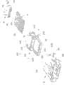
图1为本实用新型沉板型连接器安装在电路板的立体示意图。FIG. 1 is a three-dimensional schematic view of the utility model sinker type connector installed on a circuit board.
图2为本实用新型沉板型连接器与电路板分开的立体示意图。FIG. 2 is a three-dimensional schematic view of the sinker connector of the present invention separated from the circuit board.
图3为本实用新型沉板型连接器的部分分解图。Fig. 3 is a partial exploded view of the sunken plate connector of the present invention.
图4为本实用新型沉板型连接器的立体分解图。Fig. 4 is a three-dimensional exploded view of the sinker type connector of the present invention.
图5为本实用新型沉板型连接器的另一角度的立体分解图。FIG. 5 is a three-dimensional exploded view of another angle of the sinker type connector of the present invention.
【具体实施方式】【Detailed ways】
请参照图1至图5所示,本实用新型沉板型连接器100安装在印刷电路板200上,以供对接插头(未图示)插接,对接插头可以是光纤插头(未图示)、标准USB2.0A型插头(未图示)、标准USB 3.0A型插头(未图示)或薄型记忆卡(Thin card)。本实用新型沉板型连接器100包括绝缘本体、收容于绝缘本体内的若干导电端子3、光纤模块4及包覆绝缘本体的金属遮蔽壳体5。Please refer to Fig. 1 to Fig. 5, the
绝缘本体包括沿前后方向相互固持的第一本体1及第二本体2。第一本体1包括基部11及自基部11向前延伸的第一舌板12。基部11设有一前后贯穿的收容槽110以收容光纤模块4。收容槽110位于第一舌板12的上方、并沿前后方向及上下方向均与第一舌板12错开设置。基部11还设有自收容槽110内侧底壁向下凹陷的一对导引槽111,导引槽111沿前后方向延伸以导引光纤模块4自后向前插入收容槽110内。基部11前端两侧还设有向前延伸的一对挡止块113,两挡止块113位于收容槽110的两侧并向前凸伸入遮蔽壳体5内,两挡止块113还自第一舌板12两侧向上凸伸而成。薄型记忆卡可通过挡止块113进行抵挡而被阻止过度向前插入而碰撞光纤模块4。第一舌板12前端可与USB 2.0A及USB 3.0A型插头相抵,防止USB 2.0A及USB 3.0A型插头过度插入。基部11后端设有向上凸伸的凸出部114及两侧分别设有向外侧凸伸的卡块115。The insulating body includes a
第一舌板12前端设有若干凹陷部120及位于凹陷部120两侧的凸肋121。第一本体1设有前后贯穿以收容第二本体2的收容腔122。收容腔122位于凹陷部120的后方并与凹陷部120相连通。另外,收容腔122还位于收容槽110的下侧并与收容槽110间隔设置。A front end of the
第二本体2设置为水平板状结构,其固持于第一本体1的收容腔122内,与第一舌板12相结合组成绝缘本体的舌板13。第二本体2上表面凹设有第一端子槽21,下表面凹设有第二端子槽22。第一端子槽21向后贯穿第二本体2而未向前贯穿第二本体2,第二本体2后端设有与第一端子槽21连通的第一凹槽23,第二端子槽22向前贯穿第二本体2,而未向后贯穿第二本体2,第二本体2前端设有与第二端子槽22相连通的第二凹槽24。第一、第二凹槽23、24分别上下贯穿第二本体2。The
导电端子3符合标准USB 3.0传输协议,其包括若干第一端子31及第二端子32,第二端子32符合标准USB 2.0传输协议。第一端子31设有固定于第二本体2上的第一固持部311、自第一固持部311向前延伸出第二本体2的平板状第一接触部312及自第一固持部311向下延伸的第一尾部313。第一接触部312均收容于凹陷部120内并被凸肋121间隔开而防止相邻两第一接触部312相互接触。第一固持部311设有沿前后方向延伸的第一水平部314及自第一水平部314前端向上延伸的竖直部315。第一端子31的第一水平部314分别固持于第二端子槽22内,竖直部315与第一接触部312相连,竖直部315分别固持于第二凹槽24内,第一尾部313向下延伸出第一、第二本体1、2,用以穿孔焊接至电路板200。The
第二端子32设有固持于第二本体2第一端子槽21内的第二固持部321、自第二固持部321向前延伸的第二接触部322及自第二固持部321向下延伸的第二尾部323。第二接触部322成弹性臂状,第二接触部322收容于第一端子槽21内并位于第一接触部312的后方。第一、第二接触部312、322排设于舌板13表面,用以与对接插头接触。第二尾部323上端固定于第一凹槽23内,下端向下延伸出第一、第二本体1、2,用以穿孔焊接至电路板200。第一端子31的第一尾部313沿左右方向排成一排,第二端子32的第二尾部323沿左右方向排成另一排,第一尾部313位于第二尾部323的前方。The
光纤模块4固持于第一本体1收容槽110内,光纤模块4设有一本体部41及自本体部41向前延伸的一对定位柱42。本体部41前端设有位于定位柱42之间的一对透镜43。定位柱42向前延伸超出第一本体1基部11。光纤模块4设置有位于透镜43正后方的通孔44以收容光纤(未图示)进而与对接光纤插头进行光传输。本体部41下侧设有沿前后方向延伸的一对导引凸块45以与第一本体1内的导引槽111相配合,从而导引光纤模块4的安装。本体部41还设有位于后方两侧的一对弹性臂46。弹性臂46可与收容槽110的内壁相扣持以将光纤模块4固定于第一本体1内。定位柱42向前延伸未超过挡止块113,使薄型记忆卡仅能与挡止块113相抵,而不能接触定位柱42。The
遮蔽壳体5包括顶壁51、底壁52、两侧壁53及由顶壁51、底壁52、两侧壁53相连围设的用以收容对接插头的插接孔50。绝缘本体的舌板13及挡止块113向前延伸入插接孔50内。光纤模块4的透镜43暴露在插接孔50的后端,定位柱42也向前延伸入插接孔50内,用以与光纤插头对准连接。顶壁51后端具有固定第一本体1凸出部114的缺口511,凸出部114向上凸伸超过顶壁51。两侧壁53上分别设有固定第一本体1卡块115的卡扣孔535及延伸入插接孔50内的抵压弹片532,用以与对接插头相干涉。The shielding
遮蔽壳体5包括分别自两侧壁53的前缘向外侧延伸的固定片55及自两侧壁53向外侧延伸的定位片56,定位片56靠近于侧壁53后端。每一固定片55包括自侧壁53前缘向外侧弯折延伸的第一延伸片551、自第一延伸片551向后弯折延伸的第二延伸片552、自第二延伸片552朝向侧壁53延伸的第三延伸片553及自第二延伸片552竖直向下延伸的固定脚554,第一、第三延伸片551、553分别垂直于侧壁53及沉板型连接器100的插拔方向,第二延伸片552平行于侧壁53及沉板型连接器100的插拔方向。第三延伸片553位于弹片532的外侧,第三延伸片553具有位于弹片532外侧的凹口5532,用以提供弹片532的变形空间。The shielding
定位片56包括自侧壁53向后外侧水平延伸的水平部561及自水平部561向下垂直弯折延伸的定位脚562,遮蔽壳体5的底壁52及侧壁53上分别形成有因形成定位片56而留下的开口526、536。定位脚562与固定脚554沿前后方向相对齐,并分别用以焊接固定在电路板200的安装孔201内。定位片56的水平部561与电路板200之间具有大概0.1毫米的间距,使定位脚562具有一部分向上露出电路板200后,能够吸附较多焊锡,提高定位脚562的固定强度。The
本实用新型沉板型连接器100的组装时,首先,将光纤模块4向前组装于第一本体1内,及将导电端子3固定于第二本体2上,其次,将第二本体2向前组装于第一本体1内,最后,将遮蔽壳体5套设在第一本体1外部,组装完成。When assembling the
本实用新型沉板型连接器100安装在电路板200后,第一本体1的后端及固定片55的第一、第二、第三延伸片551、552、553分别向下支撑于电路板200上,防止沉板型连接器100上下晃动。当该沉板型连接器100固定在电路板200后,若受到左右方向之作用力,或相对电路板200左右晃动时,第三延伸片553将与遮蔽壳体5侧壁53相抵,可以限制遮蔽壳体5于左右方向上移动,同时阻止了固定脚554左右松动及脱离电路板200,保证了沉板型连接器100的固定效果。After the
Claims (10)
Priority Applications (2)
| Application Number | Priority Date | Filing Date | Title |
|---|---|---|---|
| CN2010206476061UCN202004173U (en) | 2010-12-08 | 2010-12-08 | Sinking plate connector |
| US13/314,211US8475218B2 (en) | 2010-12-08 | 2011-12-08 | Sinking electrical connector with an improved mounting member |
Applications Claiming Priority (1)
| Application Number | Priority Date | Filing Date | Title |
|---|---|---|---|
| CN2010206476061UCN202004173U (en) | 2010-12-08 | 2010-12-08 | Sinking plate connector |
Publications (1)
| Publication Number | Publication Date |
|---|---|
| CN202004173Utrue CN202004173U (en) | 2011-10-05 |
Family
ID=44706900
Family Applications (1)
| Application Number | Title | Priority Date | Filing Date |
|---|---|---|---|
| CN2010206476061UExpired - LifetimeCN202004173U (en) | 2010-12-08 | 2010-12-08 | Sinking plate connector |
Country Status (2)
| Country | Link |
|---|---|
| US (1) | US8475218B2 (en) |
| CN (1) | CN202004173U (en) |
Cited By (3)
| Publication number | Priority date | Publication date | Assignee | Title |
|---|---|---|---|---|
| CN104682137A (en)* | 2015-03-09 | 2015-06-03 | 连展科技(深圳)有限公司 | Electric plug connector |
| CN104901097A (en)* | 2015-06-04 | 2015-09-09 | 杨永明 | Sink plate type MINI HDMI socket |
| CN108987999A (en)* | 2018-09-12 | 2018-12-11 | 永泰电子(东莞)有限公司 | Micro coaxial cable connector assembly and its manufacturing method |
Families Citing this family (32)
| Publication number | Priority date | Publication date | Assignee | Title |
|---|---|---|---|---|
| SG185731A1 (en) | 2010-05-28 | 2013-01-30 | Apple Inc | Dual orientation connector with external contacts |
| US9293876B2 (en) | 2011-11-07 | 2016-03-22 | Apple Inc. | Techniques for configuring contacts of a connector |
| US8708745B2 (en) | 2011-11-07 | 2014-04-29 | Apple Inc. | Dual orientation electronic connector |
| US9112327B2 (en) | 2011-11-30 | 2015-08-18 | Apple Inc. | Audio/video connector for an electronic device |
| US9496665B2 (en) | 2012-02-09 | 2016-11-15 | Apple Inc. | Connector receptacle with side ground contacts |
| US8894445B2 (en)* | 2012-02-09 | 2014-11-25 | Apple Inc. | Connector receptacle with side ground contacts |
| US8920197B2 (en) | 2012-03-14 | 2014-12-30 | Apple Inc. | Connector receptacle with ground contact having split rear extensions |
| US9011176B2 (en)* | 2012-06-09 | 2015-04-21 | Apple Inc. | ESD path for connector receptacle |
| US8641455B2 (en)* | 2012-07-03 | 2014-02-04 | Cheng Uei Precision Industry Co., Ltd. | Universal serial bus connector perpendicularly mounted on a printed circuit board |
| US9065212B2 (en) | 2012-08-29 | 2015-06-23 | Apple Inc. | Connector architecture and insertion profile |
| US9093803B2 (en) | 2012-09-07 | 2015-07-28 | Apple Inc. | Plug connector |
| US9160129B2 (en)* | 2012-09-11 | 2015-10-13 | Apple Inc. | Connectors and methods for manufacturing connectors |
| US9054477B2 (en) | 2012-09-11 | 2015-06-09 | Apple Inc. | Connectors and methods for manufacturing connectors |
| US9059531B2 (en) | 2012-09-11 | 2015-06-16 | Apple Inc. | Connectors and methods for manufacturing connectors |
| US9325097B2 (en) | 2012-11-16 | 2016-04-26 | Apple Inc. | Connector contacts with thermally conductive polymer |
| US20140206209A1 (en) | 2013-01-24 | 2014-07-24 | Apple Inc. | Reversible usb connector |
| US9356404B2 (en)* | 2013-09-25 | 2016-05-31 | Hon Hai Precision Industry Co., Ltd. | Electrical connector |
| US9640885B2 (en) | 2013-11-17 | 2017-05-02 | Apple Inc. | Connector receptacle having a tongue |
| WO2015073974A2 (en) | 2013-11-17 | 2015-05-21 | Apple Inc. | Connector receptacle having a shield |
| US9363910B2 (en)* | 2014-01-03 | 2016-06-07 | Ho E Screw & Hardware Co., Ltd. | Memory stick |
| US9450339B2 (en) | 2014-01-12 | 2016-09-20 | Apple Inc. | Ground contacts for reduced-length connector inserts |
| US9515439B2 (en)* | 2014-05-26 | 2016-12-06 | Apple Inc. | Connector insert assembly |
| US9356370B2 (en) | 2014-05-26 | 2016-05-31 | Apple Inc. | Interposer for connecting a receptacle tongue to a printed circuit board |
| US9490581B2 (en) | 2014-05-26 | 2016-11-08 | Apple Inc. | Connector insert assembly |
| US10418763B2 (en)* | 2014-05-26 | 2019-09-17 | Apple Inc. | Connector insert assembly |
| CN204216285U (en)* | 2014-07-15 | 2015-03-18 | 番禺得意精密电子工业有限公司 | Electric connector |
| CN104362451B (en)* | 2014-11-06 | 2023-05-05 | 连展科技电子(昆山)有限公司 | Socket connector with bidirectional plugging function |
| CN205509067U (en)* | 2016-01-04 | 2016-08-24 | 连展科技(深圳)有限公司 | Socket electric connector |
| USD843946S1 (en)* | 2017-06-23 | 2019-03-26 | Hirose Electric Co., Ltd. | Electrical connector |
| USD843945S1 (en)* | 2017-06-23 | 2019-03-26 | Hirose Electric Co., Ltd. | Electrical connector |
| CN113178720A (en)* | 2021-04-20 | 2021-07-27 | 杭州耀芯科技有限公司 | Pluggable free space photoelectric hybrid connector |
| JP2023098099A (en) | 2021-12-28 | 2023-07-10 | ホシデン株式会社 | Connector and connection structure between circuit board and connector |
Family Cites Families (10)
| Publication number | Priority date | Publication date | Assignee | Title |
|---|---|---|---|---|
| JP3885988B2 (en)* | 2000-07-03 | 2007-02-28 | 矢崎総業株式会社 | Hybrid connector |
| US6475033B1 (en)* | 2001-10-10 | 2002-11-05 | Hon Hai Precision Ind. Co., Ltd. | Electrical connector |
| JP5227645B2 (en)* | 2008-04-21 | 2013-07-03 | 矢崎総業株式会社 | Board connector |
| US7931485B2 (en) | 2008-04-29 | 2011-04-26 | Molex Incorporated | Connector with side flange |
| CN101853995B (en)* | 2009-04-02 | 2012-05-23 | 富士康(昆山)电脑接插件有限公司 | Socket electrical connector |
| US8814443B2 (en) | 2009-06-02 | 2014-08-26 | Hon Hai Precision Industry Co., Ltd. | Connector with improved fastening structures for fastening two tongues thereof together |
| CN101931134B (en)* | 2009-06-18 | 2013-04-03 | 富士康(昆山)电脑接插件有限公司 | Connector |
| CN101930097B (en)* | 2009-06-18 | 2012-08-29 | 富士康(昆山)电脑接插件有限公司 | Connector |
| US7883371B1 (en)* | 2009-07-22 | 2011-02-08 | Hon Hai Precision Ind. Co., Ltd. | Electrical connector with improved contact footprints |
| US7699663B1 (en)* | 2009-07-29 | 2010-04-20 | Hon Hai Precision Ind. Co., Ltd. | Electrical connector with improved grounding contact |
- 2010
- 2010-12-08CNCN2010206476061Upatent/CN202004173U/ennot_activeExpired - Lifetime
- 2011
- 2011-12-08USUS13/314,211patent/US8475218B2/enactiveActive
Cited By (4)
| Publication number | Priority date | Publication date | Assignee | Title |
|---|---|---|---|---|
| CN104682137A (en)* | 2015-03-09 | 2015-06-03 | 连展科技(深圳)有限公司 | Electric plug connector |
| CN104901097A (en)* | 2015-06-04 | 2015-09-09 | 杨永明 | Sink plate type MINI HDMI socket |
| CN104901097B (en)* | 2015-06-04 | 2017-10-03 | 新昌县鸿吉电子科技有限公司 | Heavy board-like MINI HDMI sockets |
| CN108987999A (en)* | 2018-09-12 | 2018-12-11 | 永泰电子(东莞)有限公司 | Micro coaxial cable connector assembly and its manufacturing method |
Also Published As
| Publication number | Publication date |
|---|---|
| US8475218B2 (en) | 2013-07-02 |
| US20120149244A1 (en) | 2012-06-14 |
Similar Documents
| Publication | Publication Date | Title |
|---|---|---|
| CN202004173U (en) | Sinking plate connector | |
| CN201966346U (en) | Sinking plate type connector | |
| CN101989696B (en) | Connector | |
| US10205256B2 (en) | Plug and electrical connector component | |
| CN101964470B (en) | Electrical connector | |
| CN101640333B (en) | Connector | |
| CN201323275Y (en) | Electric connector | |
| CN102468567B (en) | Cable connector combination | |
| CN106207669B (en) | Cable assembly with improved cable retention | |
| CN201204309Y (en) | electrical connector | |
| CN201207447Y (en) | Electric connector component | |
| CN201081830Y (en) | Electric connector | |
| CN113422243B (en) | Electric connector | |
| TWI427873B (en) | Connector | |
| US20120156900A1 (en) | Cable assembly having balanced supporting ribs | |
| CN201639018U (en) | Electric connector | |
| CN108173034B (en) | Plug connector | |
| US12218452B2 (en) | Electrical connector with improved structural reliability | |
| CN202855957U (en) | Electric connector | |
| TWI861403B (en) | Electrical connector and assembly thereof | |
| CN103579811B (en) | Electric connector | |
| CN103545646B (en) | Micro coaxial cable connector assembly | |
| CN202474348U (en) | Electric connector | |
| CN104466545B (en) | Electric connector | |
| US8303347B2 (en) | Electrical connector for improving intensity of contacts |
Legal Events
| Date | Code | Title | Description |
|---|---|---|---|
| C14 | Grant of patent or utility model | ||
| GR01 | Patent grant | ||
| CX01 | Expiry of patent term | Granted publication date:20111005 | |
| CX01 | Expiry of patent term |