CN201884070U - Preceding geology predictor applied to tunnel fast drilling rig - Google Patents
Preceding geology predictor applied to tunnel fast drilling rigDownload PDFInfo
- Publication number
- CN201884070U CN201884070UCN2010205947147UCN201020594714UCN201884070UCN 201884070 UCN201884070 UCN 201884070UCN 2010205947147 UCN2010205947147 UCN 2010205947147UCN 201020594714 UCN201020594714 UCN 201020594714UCN 201884070 UCN201884070 UCN 201884070U
- Authority
- CN
- China
- Prior art keywords
- transmitter
- controller plc
- data storage
- programmable logic
- logic controller
- Prior art date
- Legal status (The legal status is an assumption and is not a legal conclusion. Google has not performed a legal analysis and makes no representation as to the accuracy of the status listed.)
- Expired - Fee Related
Links
- 238000005553drillingMethods0.000titleabstractdescription38
- 238000013500data storageMethods0.000claimsabstractdescription29
- 230000003993interactionEffects0.000claimsabstractdescription13
- 238000004891communicationMethods0.000claimsabstractdescription5
- XLYOFNOQVPJJNP-UHFFFAOYSA-NwaterSubstancesOXLYOFNOQVPJJNP-UHFFFAOYSA-N0.000claimsdescription19
- 239000010705motor oilSubstances0.000claimsdescription8
- 238000010276constructionMethods0.000abstractdescription15
- 230000002159abnormal effectEffects0.000abstractdescription4
- 230000009286beneficial effectEffects0.000abstractdescription3
- 238000000034methodMethods0.000description13
- 238000004458analytical methodMethods0.000description7
- 230000001186cumulative effectEffects0.000description5
- 238000010586diagramMethods0.000description5
- 239000011435rockSubstances0.000description5
- 239000003921oilSubstances0.000description4
- 238000004364calculation methodMethods0.000description2
- 230000006378damageEffects0.000description2
- 238000011161developmentMethods0.000description2
- RZTAMFZIAATZDJ-UHFFFAOYSA-NfelodipineChemical compoundCCOC(=O)C1=C(C)NC(C)=C(C(=O)OC)C1C1=CC=CC(Cl)=C1ClRZTAMFZIAATZDJ-UHFFFAOYSA-N0.000description2
- 230000006870functionEffects0.000description2
- 238000012544monitoring processMethods0.000description2
- 201000004569BlindnessDiseases0.000description1
- 238000009412basement excavationMethods0.000description1
- 230000015572biosynthetic processEffects0.000description1
- 235000019994cavaNutrition0.000description1
- 238000007405data analysisMethods0.000description1
- 230000007547defectEffects0.000description1
- 238000012938design processMethods0.000description1
- 238000006073displacement reactionMethods0.000description1
- 238000009434installationMethods0.000description1
- 230000007774longtermEffects0.000description1
- 239000013589supplementSubstances0.000description1
- 238000012795verificationMethods0.000description1
Images


Classifications
- Y—GENERAL TAGGING OF NEW TECHNOLOGICAL DEVELOPMENTS; GENERAL TAGGING OF CROSS-SECTIONAL TECHNOLOGIES SPANNING OVER SEVERAL SECTIONS OF THE IPC; TECHNICAL SUBJECTS COVERED BY FORMER USPC CROSS-REFERENCE ART COLLECTIONS [XRACs] AND DIGESTS
- Y02—TECHNOLOGIES OR APPLICATIONS FOR MITIGATION OR ADAPTATION AGAINST CLIMATE CHANGE
- Y02P—CLIMATE CHANGE MITIGATION TECHNOLOGIES IN THE PRODUCTION OR PROCESSING OF GOODS
- Y02P90/00—Enabling technologies with a potential contribution to greenhouse gas [GHG] emissions mitigation
- Y02P90/02—Total factory control, e.g. smart factories, flexible manufacturing systems [FMS] or integrated manufacturing systems [IMS]
Landscapes
- Earth Drilling (AREA)
Abstract
Translated fromChinese
Description
Translated fromChinese技术领域technical field
本实用新型涉及一种应用于隧道快速钻机的超前地质预报装置。The utility model relates to an advanced geological prediction device applied to a tunnel fast drilling machine.
背景技术Background technique
随着我国国民经济的高速发展,特别是基础设施(高速铁路、高速公路)建设得到了突飞猛进的发展,隧道施工的要求更加快速高效,其工作量和工作难度都大大增加。快速钻机在目前的隧道施工中的使用越来越普及,但是现有的快速钻机并不能在快速钻进的过程中同时完成对前方地质情况的准确分析和判断,不具有超前地质预报分析的功能。With the rapid development of my country's national economy, especially the rapid development of infrastructure (high-speed railway, expressway) construction, the requirements for tunnel construction are faster and more efficient, and the workload and difficulty of the work are greatly increased. The use of fast drilling rigs in the current tunnel construction is becoming more and more popular, but the existing fast drilling rigs cannot complete the accurate analysis and judgment of the geological conditions ahead during the rapid drilling process, and do not have the function of advanced geological forecast analysis .
在隧道施工中常常遇到长度达数公里或数十公里的大隧道,虽然在前期的勘探设计过程中都进行过相应的地质勘探工作,对施工有一定的指导意义,但由于岩体的复杂性,使得勘察所获得的数据资料与隧道开完后所揭示出来的真实情况往往有较大的偏差。这样在隧道的施工过程中就会有很大的盲目性,施工过程中经常出现难以预料的塌方、冒顶、涌水等事故。而发生事故时,往往造成巨大的设备和财产损失,甚至人员伤亡,而且处理事故的难度往往较大,因此做好超前地质预报是隧道工程建设过程中一项十分重要而有益的工作。目前虽然已有很多的物探法存在,但是仍然不能很好地实现对隧道掌子面深部异常地质情况以及其具体深度位置的准确预报。In tunnel construction, large tunnels with a length of several kilometers or tens of kilometers are often encountered. Although the corresponding geological exploration work has been carried out in the previous exploration and design process, which has certain guiding significance for the construction, due to the complexity of the rock mass Due to the nature of the tunnel, there is often a large deviation between the data obtained by the survey and the real situation revealed after the tunnel is opened. In this way, there will be a lot of blindness in the construction process of the tunnel, and unexpected accidents such as landslides, roof falls, and water gushing often occur during the construction process. When an accident occurs, it often causes huge equipment and property losses, and even casualties, and it is often difficult to deal with the accident. Therefore, it is very important and beneficial to do a good job in advanced geological forecasting in the process of tunnel construction. Although there are many geophysical prospecting methods, they still cannot accurately predict the abnormal geological conditions in the deep part of the tunnel face and its specific depth position.
实用新型内容:Utility model content:
本实用新型所要解决的技术问题是提供操作简便、预报准确的一种应用于隧道快速钻机的超前地质预报装置。The technical problem to be solved by the utility model is to provide an advanced geological forecasting device applied to a tunnel fast drilling machine with simple operation and accurate forecasting.
本实用新型解决其技术问题所采用的技术方案:The technical solution adopted by the utility model to solve its technical problems:
本实用新型包括安装在隧道快速钻机上的传感器、可编程控制器PLC、人机交互界面HMI、数据存储装置MEM、安装于数据存储装置上的数据存储卡、以及读卡器和计算机;The utility model includes a sensor installed on a tunnel fast drilling machine, a programmable controller PLC, a human-machine interaction interface HMI, a data storage device MEM, a data storage card installed on the data storage device, a card reader and a computer;
所述传感器的输出端接可编程控制器PLC的相应输入端,所述可编程控制器PLC通过通讯总线CANbus分别与人机交互界面HM I和数据存储装置MEM相连接;所述读卡器插入所述计算机的USB接口。The output terminal of the sensor is connected to the corresponding input terminal of the programmable controller PLC, and the programmable controller PLC is connected with the man-machine interaction interface HMI and the data storage device MEM respectively through the communication bus CANbus; the computer's USB port.
所述传感器包括:钻杆钻进编码器EC1、旋转马达油压变送器PT1、旋转马达流量变送器FT1、冲击压力变送器PT2、推进压力传感器-前PT3、推进压力传感器-后PT4、送水压力变送器PT5、送水流量变送器FT2、排水压力变送器PT6和排水流量变送器FT3。The sensors include: drill pipe drilling encoder EC1, rotary motor oil pressure transmitter PT1, rotary motor flow transmitter FT1, impact pressure transmitter PT2, propulsion pressure sensor-front PT3, propulsion pressure sensor-rear PT4 , Water delivery pressure transmitter PT5, water delivery flow transmitter FT2, drainage pressure transmitter PT6 and drainage flow transmitter FT3.
本实用新型的有益效果是使隧道快速钻机在完成其施工任务的同时具备了超前地质预报的功能;使用本装置完成的超前地质预报与国内其他物探法超前地质预报的方法相比较,能够较准确地给出异常地质情况的具体位置,具有很高的精度。为下一步采取合理的施工方案提供了第一手的可靠的数据资料,能够极大地减少灾害性事故的发生几率,为隧道快速、安全、高效地施工提供了可靠的技术保证,极具市场应用价值。The beneficial effect of the utility model is that the rapid tunnel drilling rig has the function of advanced geological prediction while completing its construction tasks; the advanced geological prediction completed by using this device can be more accurate compared with the methods of advanced geological prediction by other domestic geophysical exploration methods. It can accurately give the specific location of abnormal geological conditions with high precision. It provides first-hand reliable data for a reasonable construction plan in the next step, can greatly reduce the probability of disastrous accidents, and provides a reliable technical guarantee for the fast, safe and efficient construction of tunnels, which has great market application value.
附图说明Description of drawings
图1是本实用新型的原理框图;Fig. 1 is a block diagram of the utility model;
图2是各传感器与可编程控制器PLC的线路连接图;Fig. 2 is the circuit connection diagram of each sensor and programmable controller PLC;
图3是本实用新型的工作流程图;Fig. 3 is a work flow diagram of the utility model;
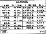
图4是人机交互界面HMI参数监控的屏幕截图;Fig. 4 is a screenshot of HMI parameter monitoring of the human-computer interaction interface;
图5是数据存储卡数据存储配置界面的屏幕截图;Fig. 5 is a screenshot of the data storage configuration interface of the data storage card;
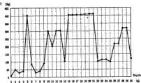
图6是钻杆旋转扭矩与钻孔累计深度之间的关系曲线图;Fig. 6 is a graph showing the relationship between the rotational torque of the drill rod and the cumulative depth of the borehole;
图7是各传感器在快速钻机油路控制上的分布示意图;Fig. 7 is a schematic diagram of the distribution of each sensor on the oil circuit control of the fast drilling rig;
图8是各传感器在快速钻机水路系统上的分布示意图。Fig. 8 is a schematic diagram of the distribution of sensors on the waterway system of the fast drilling rig.
具体实施方式Detailed ways
由图1、2所示的实施例可知,它包括安装在隧道快速钻机上的传感器、可编程控制器PLC、人机交互界面HMI、数据存储装置MEM、安装于数据存储装置上的数据存储卡、以及读卡器和计算机;From the embodiment shown in Figures 1 and 2, it can be seen that it includes sensors installed on the tunnel fast drilling machine, a programmable logic controller PLC, a human-computer interaction interface HMI, a data storage device MEM, and a data storage card installed on the data storage device. , and card readers and computers;
所述传感器的输出端接可编程控制器PLC的相应输入端,所述可编程控制器PLC通过通讯总线CANbus分别与人机交互界面HMI和数 据存储装置MEM相连接;所述读卡器插入所述计算机的USB接口。The output terminal of the sensor is connected to the corresponding input terminal of the programmable controller PLC, and the programmable controller PLC is respectively connected with the human-machine interaction interface HMI and the data storage device MEM through the communication bus CANbus; the card reader is inserted into the the computer's USB port.
所述传感器包括:钻杆钻进编码器EC1、旋转马达油压变送器PT1、旋转马达流量变送器FT1、冲击压力变送器PT2、推进压力传感器-前PT3、推进压力传感器-后PT4、送水压力变送器PT5、送水流量变送器FT2、排水压力变送器PT6和排水流量变送器FT3。The sensors include: drill pipe drilling encoder EC1, rotary motor oil pressure transmitter PT1, rotary motor flow transmitter FT1, impact pressure transmitter PT2, propulsion pressure sensor-front PT3, propulsion pressure sensor-rear PT4 , Water delivery pressure transmitter PT5, water delivery flow transmitter FT2, drainage pressure transmitter PT6 and drainage flow transmitter FT3.
所述钻杆钻进编码器EC1的“+UB”端和“0V”端分别接+24V和-24V,其输出端A和B分别接所述可编程控制器PLC的输入端IN00-IN01;所述旋转马达油压变送器PT1、旋转马达流量变送器FT1、冲击压力变送器PT2、推进压力传感器-前PT3、推进压力传感器-后PT4、送水压力变送器PT5的“+”端分别接+24V,它们的“-”端依次分别接所述可编程控制器PLC的输入端IN02-IN07;所述送水流量变送器FT2的1端接+24V,其2端和27端分别接-24V,其输出端26端接所述可编程控制器PLC的输入端I N08;所述排水压力变送器PT6的“+”端接+24V,其“-”端接所述可编程控制器PLC的输入端IN09;所述排水流量变送器FT3的1端接+24V,其2端和27端分别接-24V,其输出端26端接所述可编程控制器PLC的输入端I N10;所述可编程控制器PLC的“VBS(+)”端和“GND(-)”端分另接+24V和-24V。The "+UB" end and "0V" end of the drill pipe drilling encoder EC1 are respectively connected to +24V and -24V, and its output terminals A and B are respectively connected to the input terminals IN00-IN01 of the programmable controller PLC; The "+" of the rotary motor oil pressure transmitter PT1, rotary motor flow transmitter FT1, impact pressure transmitter PT2, propulsion pressure sensor-front PT3, propulsion pressure sensor-rear PT4, water delivery pressure transmitter PT5 The ends are respectively connected to +24V, and their "-" ends are respectively connected to the input ends IN02-IN07 of the programmable controller PLC in turn; the 1 end of the water delivery flow transmitter FT2 is connected to +24V, and its 2 ends and 27 ends connected to -24V respectively, and its
在图2中,各传感器的型号如下:钻杆钻进编码器EC1为Waycon拉线位移式增量编码器,型号为SX120-5000-3.1-G-SR-O,拉绳每前进1mm编码器输出3.1个脉冲;旋转马达油压变送器PT1、冲击压力变送器PT2、推进压力传感器-前PT3、推进压力传感器-后PT4这4个传感器选用的是HYDAC的压力变送器,型号为HDA4744-A-250-Y00;旋转马达流量变送器FT1选用的是HYDAC的涡轮式流量变送器,型号为EVS3104-A-0300-000;送水压力变送器PT5、排水压力变送器PT6选用的是Danfoss的压力变送器,型号为060G3527 MBS 3000;送水流量变送器FT2、排水流量变送器FT3选用的是E+H的电磁流量计,型号为50W-25UA0A1AA0ABAA。In Fig. 2, the models of each sensor are as follows: the drill pipe drilling encoder EC1 is a Waycon pull wire displacement incremental encoder, the model is SX120-5000-3.1-G-SR-O, and the encoder outputs when the pull wire advances 1mm. 3.1 pulse; the four sensors of rotary motor oil pressure transmitter PT1, impact pressure transmitter PT2, propulsion pressure sensor-front PT3, propulsion pressure sensor-rear PT4 are HYDAC pressure transmitters, model HDA4744 -A-250-Y00; Rotary motor flow transmitter FT1 uses HYDAC turbine flow transmitter, the model is EVS3104-A-0300-000; water delivery pressure transmitter PT5, drainage pressure transmitter PT6 selection The most used is the pressure transmitter of Danfoss, the model is 060G3527 MBS 3000; the water flow transmitter FT2 and the drainage flow transmitter FT3 are E+H electromagnetic flowmeters, the model is 50W-25UA0A1AA0ABAA.
在图2中,可编程控制器PLC选用的是IFM的车载式移动控制器,型号为CR0032,它的输入通道(IN00-IN10)根据输入信号的不同可 以分别配置成数字量输入、模拟量4-20mA输入,模拟量0-10V输入,以及高速脉冲输入等不同模式。在本实用新型中,可编程控制器PLC的输入通道配置如下:IN00、IN01两个通道配置成脉冲输入模式,IN02-IN10九个通道配置成模拟量4-20mA输入模式。In Figure 2, the programmable controller PLC chooses IFM’s vehicle-mounted mobile controller, the model is CR0032, and its input channels (IN00-IN10) can be configured as digital input and analog input according to different input signals. Different modes such as 4-20mA input, analog 0-10V input, and high-speed pulse input. In the utility model, the input channels of the programmable controller PLC are configured as follows: two channels of IN00 and IN01 are configured as pulse input mode, and nine channels of IN02-IN10 are configured as analog 4-20mA input mode.
在图1中,人机交互界面HM I选用的是IFM的对话模块,型号为CR9211,是一种用于移动车辆和工程机械的5.7″彩色显示器;数据存储装置MEM选用的是IFM的用于CANopen系统的数据存储器和记录仪,型号为CR3101,该装置可选配数据存储卡;数据存储卡选用的是IFM存储容量为1G的SD卡EC1021。In Fig. 1, the human-computer interaction interface HM I chooses the dialogue module of IFM, the model is CR9211, which is a 5.7" color display for mobile vehicles and construction machinery; the data storage device MEM chooses the IFM for The data memory and recorder of the CANopen system, the model is CR3101, and the device can be equipped with a data memory card; the data memory card is the SD card EC1021 with a storage capacity of IFM of 1G.
各传感器的在快速钻机上的分布安装位置见图7、图8,钻杆钻进编码器EC1是拉绳式编码器,拉绳的一端固定,另一端连接至由动力头推进油缸驱动的钻杆上,当快速钻机钻进过程中,钻杆会拉动编码器EC1的拉绳前进,这样就可以通过EC1获取钻孔累计深度Depth以及钻杆推进速度Vs;推进压力传感器-前PT3和推进压力传感器-后PT4均装设在推进油缸控制油路上,通过它们的测量值可以分别计算钻杆的推进力F1和起拨力F2;旋转马达油压变送器PT1和旋转马达流量变送器FT1均装设在动力头旋转马达的控制油路上,通过它们的测量值可以分别计算钻杆旋转扭矩T和钻杆转速n,冲击压力变送器PT2装设在动力头冲击锤的控制油路上,通过其测量值可以计算钻孔冲击锤的打击能E、打击次数Beats、破坏能EV;送水压力变送器PT5和送水流量变送器FT2均装设在快速钻机钻进过程中给钻杆送水的回路上;排水压力变送器PT6和排水流量变送器FT3均装设在快速钻机钻进过程中钻杆的排水回路上,这样通过对PT5、FT2和PT6、FT3测量数值的比较,可以判断前方是否有空洞或地下暗河等地质情况。The distribution and installation positions of the sensors on the fast drilling rig are shown in Figure 7 and Figure 8. The drill pipe drilling encoder EC1 is a rope-drawn encoder. One end of the rope is fixed, and the other end is connected to the drill driven by the power head propulsion cylinder. On the rod, when the fast drilling rig is drilling, the drill rod will pull the pull rope of the encoder EC1 to move forward, so that the accumulated drilling depth Depth and the drill rod advancing speed Vs can be obtained through EC1; advancing pressure sensor - front PT3 and advancing pressure The sensor-rear PT4 is installed on the control oil circuit of the propulsion cylinder, and the propulsion force F1 and pull-out force F2 of the drill pipe can be calculated through their measured values; the rotary motor oil pressure transmitter PT1 and the rotary motor flow transmitter FT1 They are all installed on the control oil circuit of the rotary motor of the power head, and the drill pipe rotation torque T and the drill pipe speed n can be calculated respectively through their measured values. The impact pressure transmitter PT2 is installed on the control oil circuit of the impact hammer of the power head. The impact energy E, the number of impacts Beats, and the destruction energy EV of the drilling impact hammer can be calculated through its measured values; the water delivery pressure transmitter PT5 and the water delivery flow transmitter FT2 are both installed in the fast drilling process to send water to the drill pipe on the circuit; the drainage pressure transmitter PT6 and the drainage flow transmitter FT3 are installed on the drainage circuit of the drill pipe during the drilling process of the fast drilling rig, so that by comparing the measured values of PT5, FT2 and PT6, FT3, it can be Judging whether there are geological conditions such as caves or underground rivers ahead.
总之,通过设置上述传感器可以即时地测量快速钻机工作过程中钻杆的推进、旋转、冲击参数,钻杆钻进的深度、速度参数,以及送水回路与排水回路的比较参数。通过这些参数就可以间接地反应前方的岩质构成情况,得出准确可靠的超前地质预报结果。In a word, by setting the above-mentioned sensors, the propulsion, rotation and impact parameters of the drill pipe during the working process of the fast drilling rig, the drilling depth and speed parameters of the drill pipe, and the comparison parameters of the water supply circuit and the drainage circuit can be measured in real time. Through these parameters, it can indirectly reflect the composition of the rock ahead, and obtain accurate and reliable advanced geological prediction results.
本实施例的工作原理如下:The working principle of this embodiment is as follows:
1、启动可编程控制器PLC,在快速钻机的工作过程中各传感器的输出信号会产生动态的变化,此变化是跟前方地质情况的变化密切相关的。这些信号通过可编程控制器PLC的输入通道IN00-IN10被实时地采集上来,同时在PLC内完成相关运算,并最终得出需要保存的关键数据(即附表1)。1. Start the programmable controller PLC. During the working process of the fast drilling rig, the output signals of each sensor will produce dynamic changes. This change is closely related to the change of the geological conditions ahead. These signals are collected in real time through the input channels IN00-IN10 of the programmable controller PLC, and at the same time, the relevant calculations are completed in the PLC, and finally the key data that needs to be saved (that is, attached table 1) are obtained.
具体的计算方法如下:The specific calculation method is as follows:
(1)钻孔累计深度: 
式中:Pulses为钻杆钻进编码器EC1输入脉冲累计个数(1mm/3.1pulses)In the formula: Pulses is the cumulative number of input pulses of drill pipe drilling encoder EC1 (1mm/3.1pulses)
(2)钻杆推进速度: 
式中:f为钻杆钻进编码器EC1输入脉冲的频率(HZ)In the formula: f is the frequency of the input pulse of the drill pipe drilling encoder EC1 (HZ)
(3)钻杆转速: 
式中:Q1为旋转马达流量变送器FT1测量的流量值(L/min)Where: Q1 is the flow rate measured by the rotary motor flow transmitter FT1 (L/min)
(4)钻杆旋转扭矩: (4) Drill pipe rotation torque:
式中:P1为旋转马达油压变送器PT1测量的压力值(MPa)Where: P1 is the pressure value measured by the rotary motor oil pressure transmitter PT1 (MPa)
(5)打击能:E=25*P2(J)(5) Impact energy: E=25*P2(J)
式中:P2为冲击压力变送器PT2测量的压力值(MPa)Where: P2 is the pressure value measured by the impact pressure transmitter PT2 (MPa)
(6)打击次数:Beats=1035+68.6*P2(b/min)(6) Beat times: Beats=1035+68.6*P2(b/min)
式中:P2为冲击压力变送器PT2测量的压力值(MPa)Where: P2 is the pressure value measured by the impact pressure transmitter PT2 (MPa)
(7)破坏能: 
式中:E为打击能(J)In the formula: E is the impact energy (J)
Beats为打击次数(b/min)Beats is the number of strikes (b/min)
VS为钻杆推进速度(m/min)VS is the drill pipe advancing speed (m/min)
S为挖掘断面面积(cm2) 
(8)推进力:F1=2*P3(N)(8) Propelling force: F1=2*P3(N)
式中:P3为推进压力传感器-前PT3测量的压力值(MPa)In the formula: P3 is the pressure value measured by the propulsion pressure sensor-front PT3 (MPa)
(9)起拔力:F2=3.93*P4(N)(9) Pull-out force: F2=3.93*P4(N)
式中:P4为推进压力传感器-后PT4测量的压力值(MPa)In the formula: P4 is the pressure value measured by the propulsion pressure sensor-rear PT4 (MPa)
(10)送水压力:P5由送水压力变送器PT5测出;(10) Water supply pressure: P5 is measured by the water supply pressure transmitter PT5;
(11)送水流量:Q5由送水流量变送器FT2测出;(11) Water delivery flow: Q5 is measured by water delivery flow transmitter FT2;
(12)排水压力:P6由排水压力变送器PT6测出;(12) Drainage pressure: P6 is measured by the drainage pressure transmitter PT6;
(13)排水流量:Q3由排水流量变送器FT3测出。(13) Drainage flow: Q3 is measured by the drainage flow transmitter FT3.
2、可编程控制器PLC通过CAN bus总线通讯把上述关键数据分别传送给人机交互界面HMI和数据存储装置MEM,人机交互界面HMI用于数据的在线显示(见图4),便于操作人员监控;数据存储装置MEM和其内置的数据存储卡(SD卡)负责上述关键数据的记录和保存,数据每存储一次的时间间隔为1s。数据存储卡(SD卡)的容量较大,可以存储大约上百天的数据,以适应钻机长时间钻孔的需求。2. The programmable controller PLC transmits the above key data to the human-machine interaction interface HMI and the data storage device MEM through CAN bus communication, and the human-machine interaction interface HMI is used for online display of data (see Figure 4), which is convenient for operators Monitoring; the data storage device MEM and its built-in data storage card (SD card) are responsible for the recording and storage of the above key data, and the time interval for each data storage is 1s. The data storage card (SD card) has a large capacity and can store about hundreds of days of data to meet the needs of the drilling rig for long-term drilling.
3、当钻机打完一个或几个样孔或工作告一段落,需要对前方的地质情况进行分析时,只需从数据存储装置MEM上取走数据存储卡(SD卡),此时SD卡中已经存储了大量的能反映前方地质情况的CSV格式数据。3. When the drilling rig has completed one or several sample holes or the work has come to an end, and it is necessary to analyze the geological conditions ahead, it is only necessary to remove the data storage card (SD card) from the data storage device MEM. A large amount of data in CSV format that can reflect the geological conditions ahead has been stored.
4、可以把数据存储卡(SD卡)带到优越的办公环境中,然后把SD卡放入一个读卡器,再把读卡器插到计算机上的USB接口。通过IFM的CANmem-Configrator软件对SD卡内部的数据进行读取,然后在计算机PC上存储为*CSV格式的文件,此种格式的文件可以被常用的办公软件Microsoft Excel识别、读取、分析、处理和形成曲线。附表2即是Excel从SD卡读取的CSV格式关键数据表单的一个实例,上面有钻孔累计深度Depth、钻杆旋转扭矩T和数据的存储时间等。图6是根据附表2绘制的以深度30m为例的钻杆旋转扭矩与钻孔累计深度之间的关系曲线。以此为例可以形成和保存多种关系曲线。通过这些曲线不难发现,它比较真实而准确地反映了前方地质情况的变化。例如:岩层硬度增大时,需要钻杆提供比较大的扭矩等。4. You can take the data storage card (SD card) into a superior office environment, then put the SD card into a card reader, and then insert the card reader into the USB interface on the computer. Read the data inside the SD card through the CANmem-Configrator software of IFM, and then store it as a file in *CSV format on the computer PC. The file in this format can be recognized, read, analyzed, and read by the commonly used office software Microsoft Excel. Manipulate and form curves. Attached Table 2 is an example of the key data sheet in CSV format read by Excel from the SD card, which includes the cumulative drilling depth Depth, the rotational torque T of the drill pipe, and the storage time of the data. Fig. 6 is the relationship curve between the rotational torque of the drill pipe and the cumulative depth of the drilled hole drawn according to the attached table 2, taking the depth of 30m as an example. Using this as an example, various relationship curves can be formed and saved. It is not difficult to find through these curves that it truly and accurately reflects the changes in the geological conditions ahead. For example: when the hardness of the rock formation increases, the drill pipe needs to provide a relatively large torque, etc.
5、另外可以通过连接至计算机的打印机打印出上面Excel形成的各条能反映岩质情况的关系曲线,以便于进一步分析使用。5. In addition, a printer connected to a computer can be used to print out the relationship curves that can reflect the rock quality formed by the above Excel, so as to facilitate further analysis and use.
6、根据上述关系曲线图,有丰富经验的操作人员或相关专家,可以对前方的地质情况做非常准确的分析判断,并进一步得出详尽的分析报告。6. According to the above relationship graph, experienced operators or relevant experts can make very accurate analysis and judgment on the geological situation ahead, and further draw a detailed analysis report.
本实用新型的应用,不仅填补了国内快速钻机性能上的缺陷,同时由于本实用新型更贴近实际,通过图形化的数据分析,能够实现对掌子面前方的异常地质情况的准确预报,这对于减少塌方、合理选择施工方案、实现快速安全的施工提供了可靠的技术保证。采用本实用新型来实现超前地质预报是对其他物探方法的有力补充,提供了一种相互印证的新手段,并且本装置在完成某些具有特殊地质构造的预报中,往往是唯一准确可靠的分析系统和手段。The application of this utility model not only fills up the defects in the performance of domestic fast drilling rigs, but at the same time, because the utility model is closer to reality, it can realize accurate forecasting of abnormal geological conditions in front of the drill face through graphical data analysis. Reducing landslides, choosing a reasonable construction plan, and realizing fast and safe construction provide a reliable technical guarantee. Adopting the utility model to realize advanced geological prediction is a powerful supplement to other geophysical prospecting methods, and provides a new means of mutual verification, and this device is often the only accurate and reliable analysis in completing some predictions with special geological structures systems and means.
附表1:岩石分析存储数据Attached Table 1: Rock Analysis Storage Data
附表2:从数据存储卡调出的关键数据表Attached Table 2: Key Data Sheet Called from the Data Storage Card

Claims (4)
Priority Applications (1)
| Application Number | Priority Date | Filing Date | Title |
|---|---|---|---|
| CN2010205947147UCN201884070U (en) | 2010-11-08 | 2010-11-08 | Preceding geology predictor applied to tunnel fast drilling rig |
Applications Claiming Priority (1)
| Application Number | Priority Date | Filing Date | Title |
|---|---|---|---|
| CN2010205947147UCN201884070U (en) | 2010-11-08 | 2010-11-08 | Preceding geology predictor applied to tunnel fast drilling rig |
Publications (1)
| Publication Number | Publication Date |
|---|---|
| CN201884070Utrue CN201884070U (en) | 2011-06-29 |
Family
ID=44181610
Family Applications (1)
| Application Number | Title | Priority Date | Filing Date |
|---|---|---|---|
| CN2010205947147UExpired - Fee RelatedCN201884070U (en) | 2010-11-08 | 2010-11-08 | Preceding geology predictor applied to tunnel fast drilling rig |
Country Status (1)
| Country | Link |
|---|---|
| CN (1) | CN201884070U (en) |
Cited By (8)
| Publication number | Priority date | Publication date | Assignee | Title |
|---|---|---|---|---|
| CN102434207A (en)* | 2011-09-19 | 2012-05-02 | 山东大学 | A multi-channel trigger device and method for tunnel TSP advanced geological prediction signal |
| CN103308946A (en)* | 2013-05-14 | 2013-09-18 | 中国科学院武汉岩土力学研究所 | Tunnel advance geology forecast method based on blast hole drilling information |
| CN105354179A (en)* | 2015-11-02 | 2016-02-24 | 武汉钢铁(集团)公司 | Coke dry quenching report generation method |
| CN105422088A (en)* | 2015-11-11 | 2016-03-23 | 中国煤炭科工集团太原研究院有限公司 | Coal mine roadway geological parameter on-line monitoring system |
| CN108303561A (en)* | 2017-11-21 | 2018-07-20 | 中国地质大学(北京) | A kind of measurement while drilling device suitable for mine working advance geologic prediction |
| CN108678776A (en)* | 2018-03-29 | 2018-10-19 | 中交路桥北方工程有限公司 | Sandy clay geology tunnel treatment of roof collapse method |
| CN110107274A (en)* | 2019-04-18 | 2019-08-09 | 中铁工程装备集团有限公司 | TBM jumbolter real time on-line monitoring system and monitoring method based on hydraulic system |
| CN116025382A (en)* | 2023-01-17 | 2023-04-28 | 中铁三局集团有限公司 | Advanced grouting equipment and advanced grouting method |
- 2010
- 2010-11-08CNCN2010205947147Upatent/CN201884070U/ennot_activeExpired - Fee Related
Cited By (12)
| Publication number | Priority date | Publication date | Assignee | Title |
|---|---|---|---|---|
| CN102434207A (en)* | 2011-09-19 | 2012-05-02 | 山东大学 | A multi-channel trigger device and method for tunnel TSP advanced geological prediction signal |
| CN102434207B (en)* | 2011-09-19 | 2014-06-18 | 山东大学 | Multi-channel trigger device and multi-channel trigger method for tunnel TSP (Tunnel Seism Prediction) advanced geological prediction signal |
| CN103308946A (en)* | 2013-05-14 | 2013-09-18 | 中国科学院武汉岩土力学研究所 | Tunnel advance geology forecast method based on blast hole drilling information |
| CN105354179A (en)* | 2015-11-02 | 2016-02-24 | 武汉钢铁(集团)公司 | Coke dry quenching report generation method |
| CN105422088A (en)* | 2015-11-11 | 2016-03-23 | 中国煤炭科工集团太原研究院有限公司 | Coal mine roadway geological parameter on-line monitoring system |
| CN105422088B (en)* | 2015-11-11 | 2020-02-07 | 中国煤炭科工集团太原研究院有限公司 | Coal mine tunnel geological parameter on-line monitoring system |
| CN108303561A (en)* | 2017-11-21 | 2018-07-20 | 中国地质大学(北京) | A kind of measurement while drilling device suitable for mine working advance geologic prediction |
| CN108303561B (en)* | 2017-11-21 | 2024-04-05 | 中国地质大学(北京) | Measurement while drilling device suitable for advanced geological forecast of mine roadway |
| CN108678776A (en)* | 2018-03-29 | 2018-10-19 | 中交路桥北方工程有限公司 | Sandy clay geology tunnel treatment of roof collapse method |
| CN110107274A (en)* | 2019-04-18 | 2019-08-09 | 中铁工程装备集团有限公司 | TBM jumbolter real time on-line monitoring system and monitoring method based on hydraulic system |
| CN110107274B (en)* | 2019-04-18 | 2023-06-13 | 中铁工程装备集团有限公司 | Real-time online monitoring system and monitoring method for TBM (Tunnel boring machine) jumbolter based on hydraulic system |
| CN116025382A (en)* | 2023-01-17 | 2023-04-28 | 中铁三局集团有限公司 | Advanced grouting equipment and advanced grouting method |
Similar Documents
| Publication | Publication Date | Title |
|---|---|---|
| CN201884070U (en) | Preceding geology predictor applied to tunnel fast drilling rig | |
| US11899154B2 (en) | DAS same-well monitoring real-time microseismic effective event identification method based on deep learning | |
| CN103018788B (en) | Profound tunnel unfavorable geology and Mechanical property forward probe device and method | |
| CN113175302B (en) | A small drilling rig system and evaluation method for intelligent perception of rock quality | |
| RU2616053C1 (en) | Optimized drill string rotation during directional drilling in the sliding mode | |
| CN202975361U (en) | Advance detection apparatus for unfavorable geology and rock mass mechanical property of deep and long tunnel | |
| CN204405865U (en) | Advanced geology for tunnel construction predictor | |
| CN202000991U (en) | Device for acquiring data of down-the-hole drill in drilling process in real time | |
| CN111126735B (en) | Drilling digital twin system | |
| CN203271714U (en) | Drilling machine data collection and monitoring control system | |
| CN103046918A (en) | Method and system for optimizing drilling parameters | |
| CN108363873A (en) | A kind of lithology discrimination method based on mining-drilling machine | |
| CN110965991B (en) | Method and device for identifying mineral components of rock under drilling based on artificial intelligence | |
| CN103696760A (en) | Near-bit measurement while drilling sound wave short-distance transmission method and transmission device | |
| CN104089595B (en) | Stope base object model ruptures determination of distance method in advance | |
| CN113279747A (en) | System and method for allocating drilling mud formula and performance parameters | |
| CN117272041A (en) | Rock mass condition sensing method based on cutterhead vibration signals during tunneling of tunnel boring machine | |
| CN202900265U (en) | Near-bit measurement-while-drilling sound wave short-distance transmission device | |
| CN104727815A (en) | Real-time well drilling formation correction method and device | |
| CN205715073U (en) | A kind of intelligence rig electrohydraulic control system | |
| CN106032750B (en) | Geological logging instrument based on drilling energy spectrum | |
| CN110965941A (en) | A kind of geosteering drilling test tool and using method | |
| CN106761804A (en) | One kind is equipped on TBM advanced hydraulic pressure detection device and method in real time | |
| CN203224223U (en) | Device for detecting layer separation of surrounding rock based on displacement sensors and wireless transmission | |
| CN204877433U (en) | Intelligence rock rig control system |
Legal Events
| Date | Code | Title | Description |
|---|---|---|---|
| C14 | Grant of patent or utility model | ||
| GR01 | Patent grant | ||
| C17 | Cessation of patent right | ||
| CF01 | Termination of patent right due to non-payment of annual fee | Granted publication date:20110629 Termination date:20131108 |