CN201859424U - Display touch system - Google Patents
Display touch systemDownload PDFInfo
- Publication number
- CN201859424U CN201859424UCN2010205904438UCN201020590443UCN201859424UCN 201859424 UCN201859424 UCN 201859424UCN 2010205904438 UCN2010205904438 UCN 2010205904438UCN 201020590443 UCN201020590443 UCN 201020590443UCN 201859424 UCN201859424 UCN 201859424U
- Authority
- CN
- China
- Prior art keywords
- screen
- light source
- display touch
- light
- display
- Prior art date
- Legal status (The legal status is an assumption and is not a legal conclusion. Google has not performed a legal analysis and makes no representation as to the accuracy of the status listed.)
- Expired - Fee Related
Links
- 230000003287optical effectEffects0.000claimsabstractdescription42
- 238000012545processingMethods0.000claimsabstractdescription19
- 238000010586diagramMethods0.000description12
- 238000004519manufacturing processMethods0.000description4
- 238000000034methodMethods0.000description3
- 230000000903blocking effectEffects0.000description2
- 230000008859changeEffects0.000description2
- 238000001514detection methodMethods0.000description2
- 238000004364calculation methodMethods0.000description1
- 238000006073displacement reactionMethods0.000description1
- 238000005516engineering processMethods0.000description1
- 238000000691measurement methodMethods0.000description1
- 238000012986modificationMethods0.000description1
- 230000004048modificationEffects0.000description1
- 238000003825pressingMethods0.000description1
- 238000012827research and developmentMethods0.000description1
- 230000001568sexual effectEffects0.000description1
Images


Landscapes
- Position Input By Displaying (AREA)
Abstract
Description
Translated fromChinese技术领域technical field
本实用新型涉及触控结构领域,特别涉及一种显示器触控系统。The utility model relates to the field of touch structure, in particular to a display touch system.
背景技术Background technique
近年来,由于平面显示器的制造成本显著地降低,因此平面显示器已逐渐成为家庭电视及计算机用屏幕的主流。此外,因为平面显示器较传统上使用阴极射线管(Cathode Ray Tube,CRT)的电视更加轻、薄,因此,在火车站、医院、便利商店或电影院等公共场所,都可以发现越来越多的平面显示器,该平面显示器不但可用于讯息的显示,还可用于广告的目的,其商业上的应用可说是越来越广泛。In recent years, since the manufacturing cost of the flat-panel display has been significantly reduced, the flat-panel display has gradually become the mainstream of home TV and computer screens. In addition, because flat-panel displays are lighter and thinner than traditional TVs using cathode ray tubes (Cathode Ray Tube, CRT), more and more displays can be found in public places such as train stations, hospitals, convenience stores or movie theaters. Flat-panel display, the flat-panel display can not only be used for information display, but also can be used for advertising purposes, and its commercial application can be said to be more and more extensive.
随着人们对电子设备或平面显示器在功能上的要求日趋多样化,其相关的科技研发、制造技术也随着日新月异。例如,触控屏幕(Touch Screen)的需求,可以让人们方便操作计算机、手机、音响、冰箱或其他电子设备;通过其屏幕显示与屏幕按压操控的方式,人们就可以舍弃复杂的键盘、按键操作,通过屏幕清楚标示的图案与人性化的接口来同时达到显示与触控操作的目的。As people's requirements on the functions of electronic devices or flat-panel displays are becoming more and more diversified, the related technological research and development and manufacturing technologies are also changing with each passing day. For example, the demand for touch screen can make it convenient for people to operate computers, mobile phones, stereos, refrigerators or other electronic equipment; through its screen display and screen pressing and control, people can abandon the complicated keyboard and button operation. , through the clearly marked patterns on the screen and the humanized interface to achieve the purpose of display and touch operation at the same time.
目前大尺寸触控屏幕(一般而言大于10.1寸为大尺寸)以电阻式及电容式这两种方式最为常见。电阻式与电容式的触控屏幕均是通过改变屏幕表面的电性特征,而达到侦测手指位置的目的。然而,前述两种触控方式在做到大尺寸多点触控时,其成本会随着触控屏幕的尺寸增加而提高;而且,电阻式在屏幕表面布上一层线路来侦测其电性特征,这会使该屏幕的亮度降低,电容式需以手指直接接触,具有通过手套就无法使用的问题。因此,仍有其不便之处。At present, large-size touch screens (generally speaking, larger than 10.1 inches are large sizes) are most commonly used in two ways: resistive and capacitive. Both resistive and capacitive touch screens achieve the purpose of detecting finger positions by changing the electrical characteristics of the screen surface. However, when the above two touch methods achieve large-scale multi-touch, the cost will increase with the increase of the size of the touch screen; moreover, the resistive method lays a layer of lines on the surface of the screen to detect its electrical Sexual characteristics, which will reduce the brightness of the screen, and the capacitive type needs to be directly touched by fingers, which has the problem that it cannot be used through gloves. Therefore, there is still its inconvenience.
因此,如何降低触控屏幕的制造成本,且不降低该屏幕的亮度,这是本领域具有公知常识者努力的目标。Therefore, how to reduce the manufacturing cost of the touch screen without reducing the brightness of the screen is the goal of those skilled in the art.
实用新型内容Utility model content
本实用新型的主要目的在于降低触控屏幕的制造成本。The main purpose of the utility model is to reduce the manufacturing cost of the touch screen.
本实用新型的另一目的在于使触控屏幕维持其应有的亮度,让使用者可以使用手套或是任意介质(如笔等)代替手指触控屏幕。Another purpose of the present invention is to maintain the proper brightness of the touch screen, so that the user can use gloves or any medium (such as a pen) to replace the finger touch screen.
为了达到上述目的,本实用新型提供一种显示器触控系统,其设置于一显示器内,该显示器触控系统包括有一屏幕、至少两灯源模块、至少一光学传感器及至少一图像处理模块。该灯源模块为长轴型结构,且可垂直轴向而射出光线,每一灯源模块射出的多条光线构成一光投射面,将该些灯源模块设置于该屏幕的相异侧边,使该些光投射面与该屏幕互呈平行。该光学传感器设置于该屏幕的相异角落,用以实时地拍摄该光投射面周边的不透光物体,用以产生并输出多个影像信号。每一图像处理模块分别与一光学传感器相接,用以接收多个影像信号,并通过分析计算该些影像信号而得到并输出至少一位置信号。In order to achieve the above object, the utility model provides a display touch system, which is arranged in a display, and the display touch system includes a screen, at least two light source modules, at least one optical sensor and at least one image processing module. The light source module has a long-axis structure and can emit light perpendicular to the axis. The multiple light rays emitted by each light source module form a light projection surface, and these light source modules are arranged on different sides of the screen. , so that the light projection surfaces and the screen are parallel to each other. The optical sensors are arranged at different corners of the screen for real-time shooting of opaque objects around the light projection surface to generate and output a plurality of image signals. Each image processing module is respectively connected with an optical sensor to receive a plurality of image signals, and obtain and output at least one position signal by analyzing and calculating the image signals.
如上所述的显示器触控系统,其中,该光学传感器为摄影机、照相机或电荷耦合组件(Charge Coupled Device,CCD)。The display touch system as described above, wherein the optical sensor is a video camera, a camera or a charge coupled device (Charge Coupled Device, CCD).
如上所述的显示器触控系统,其中,该图像处理模块为中央处理器(Central Processing Unit,CPU)或缩放控制器(Scalar)。In the display touch control system described above, the image processing module is a central processing unit (Central Processing Unit, CPU) or a scaling controller (Scalar).
如上所述的显示器触控系统,其中,该灯源模块射出的多条光线互为平行。In the display touch control system described above, the multiple light rays emitted by the light source module are parallel to each other.
如上所述的显示器触控系统,其中,至少两灯源模块互呈垂直设置。In the display touch control system as described above, at least two light source modules are arranged vertically to each other.
如上所述的显示器触控系统,其中,该光学传感器的数目为二,且分别设置于该屏幕的两相对应的角落,或分别设置于该屏幕的同一侧边的角落。In the display touch control system described above, the number of the optical sensors is two, and they are respectively disposed at two corresponding corners of the screen, or respectively disposed at corners of the same side of the screen.
如上所述的显示器触控系统,其中,该光学传感器的数目为三或四,且多个光学传感器不设置于同一直线。In the display touch system as described above, the number of the optical sensors is three or four, and the plurality of optical sensors are not arranged on the same straight line.
由此,本实用新型所述的显示器触控系统可达到触控操控任意计算机、手机、音响、冰箱或电子设备的功能,而无需使用昂贵的电容式、电阻式触控系统。还有,因为该显示器触控系统采用一种非接触式的量测方式,因此不会降低屏幕的亮度,具有实用的商业价值。Therefore, the display touch control system described in the present invention can achieve the function of touch control of any computer, mobile phone, stereo, refrigerator or electronic equipment without using expensive capacitive or resistive touch systems. In addition, because the display touch system adopts a non-contact measurement method, it will not reduce the brightness of the screen, and has practical commercial value.
附图说明Description of drawings
图1为本实用新型第一实施例提供的显示器触控系统示意图。FIG. 1 is a schematic diagram of a display touch system provided by the first embodiment of the present invention.
图2为本实用新型第二实施例提供的显示器触控系统示意图。FIG. 2 is a schematic diagram of a display touch system provided by the second embodiment of the present invention.
图3为本实用新型第三实施例提供的显示器触控系统示意图。FIG. 3 is a schematic diagram of a display touch system provided by a third embodiment of the present invention.
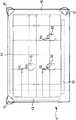
图4为本实用新型第四实施例提供的显示器触控系统示意图。FIG. 4 is a schematic diagram of a display touch system provided by a fourth embodiment of the present invention.
图5为本实用新型第五实施例提供的显示器触控系统示意图。FIG. 5 is a schematic diagram of a display touch system provided by a fifth embodiment of the present invention.
图6为本实用新型提供的显示器触控系统的功能方块图。FIG. 6 is a functional block diagram of the display touch system provided by the present invention.
【主要部分代表符号】【Main part representative symbols】
1、2、3、4、5 显示器触控系统1, 2, 3, 4, 5 Display touch system
11、21、31、41、51 光学传感器11, 21, 31, 41, 51 Optical sensor
13、23、33、43、53 灯源模块13, 23, 33, 43, 53 light source module
15、25、35、45、55 屏幕15, 25, 35, 45, 55 screens
44 图像处理模块44 image processing module
9 计算机9 computer
H1、H2、H3 手指H1, H2, H3 fingers
P1、P2、P3 触控点P1, P2, P3 touch points
Sα、Sβ、Sψ影像信号Sα , Sβ , Sψ image signals
SP1、SP2、SP3 位置信号SP1, SP2, SP3 position signal
具体实施方式Detailed ways
为使本实用新型的目的、技术方案和优点更加清楚,下面将结合附图对本实用新型实施方式作进一步地详细描述。In order to make the purpose, technical solutions and advantages of the present utility model clearer, the implementation of the present utility model will be further described in detail below in conjunction with the accompanying drawings.
请参见图1,图1为本实用新型第一实施例提供的显示器触控系统示意图。如图1所示,一显示器触控系统1,其设置于一显示器内,该显示器触控系统1包括有一屏幕15、两灯源模块13及一光学传感器11。该屏幕15可用以显示影像视讯画面。该些灯源模块13均为长轴型结构,且可垂直轴向而射出光线,两灯源模块13分别设置于该屏幕15的上侧边与左侧边而互呈垂直;在此,上侧边的灯源模块13其长轴呈左右方向设置,而其光线则垂直该长轴而朝下射出;左侧边的灯源模块13其长轴呈上下方向设置,而其光线则垂直该长轴而朝右射出。因此,上侧边的灯源模块13所射出的光线会与左侧边的灯源模块13射出的光线垂直。每一灯源模块13射出的多条光线会构成一光投射面(如虚线所示),将该些灯源模块13设置于该屏幕15的上侧边与左侧边,即可使上侧边的灯源模块13其光投射面由上往下投射,左侧边的灯源模块13其光投射面由左往右投射;而且,上侧边、左侧边的灯源模块13所射出的多条光线均与该屏幕15平行;即该些光投射面与该屏幕15互呈平行。在较佳实施例中,该灯源模块13是通过发光二极管(Light Emitting Diode,LED)及导光条(未绘示)所组成,该发光二极管用以发射红外线(Infrared)频段的不可见光,该导光条用以导引该不可见光,使不可见光垂直该灯源模块13的长轴而射出。在其他实施例中,该灯源模块13也可以是通过冷阴极荧光灯管(Cold Cathode Fluorescent Lamps,CCFL)来射出光线。Please refer to FIG. 1 . FIG. 1 is a schematic diagram of a display touch control system provided by the first embodiment of the present invention. As shown in FIG. 1 , a display touch system 1 is set in a display, and the display touch system 1 includes a
该光学传感器11设置于该屏幕15的右上角落,用以实时地拍摄该光投射面周边的不透光物体;一般而言,通常会通过人的手指H1来达到触控的目的,因此,如图1所示,本实施例的不透光物体为人的手指H1,该手指H1所按压的位置即为触控点P1。本实用新型的目的,是通过光学感测的方式,来侦测人的手指H1的位置,进而得到该触控点P1的位移变化、速度变化,并用以控制、操作电子设备的软件或硬件;因此,其感测的原理为:a.利用该光学传感器11实时地拍摄该屏幕15周边的光投射面,b.人的手指H1因为不可透光性而产生光线阻断的遮断效应,以及c.两灯源模块13的光线投射方向互相垂直;所以,即可由该光学传感器11侦测得到该触控点P1其相对应的纵坐标与横坐标。因此,不论手指H1移到该屏幕15上的任何一位置,均可被侦测到。在较佳实施例中,该光学传感器11可为摄影机、照相机或电荷耦合组件(Charge Coupled Device,CCD)。The optical sensor 11 is arranged at the upper right corner of the
此外,本实用新型还有其他的设置方式。请参见图2,图2为本实用新型第二实施例提供的显示器触控系统示意图。如图2所示,该显示器触控系统2包括有一屏幕25、两灯源模块23及一光学传感器21。其中,该光学传感器21设置于该屏幕25的左上角落而同时与两灯源模块23相邻。In addition, the utility model also has other setting modes. Please refer to FIG. 2 . FIG. 2 is a schematic diagram of a display touch control system provided by a second embodiment of the present invention. As shown in FIG. 2 , the
还有,为了使侦测的触控点更多,侦测的坐标更精准,藉以更进一步地消除判断错误的状况,本实用新型的显示器触控系统更进一步地揭露了使用更多光学传感器与灯源模块的实施例。请参见图3,图3为本实用新型第三实施例提供的显示器触控系统示意图。如图3所示,该显示器触控系统3包括有一屏幕35、三个灯源模块33及两光学传感器31。其中,两光学传感器31设置于该屏幕35的左上角与右上角,三个灯源模块33设置于该屏幕35的左侧边、右侧边及上侧边,因此,每一光学传感器31均同时与两个灯源模块33相邻。在本实施例中,因为该手指H1的触控点P1与该手指H2的触控点P2具有相同的水平高度,因此一个光学传感器31可能会有误判或无法辨识的状况,所以本实施例即通过第二个光学传感器31来补偿其误差,消除误判或无法辨识的机率,提高精准度。Also, in order to make more detected touch points and more accurate detected coordinates, so as to further eliminate the situation of misjudgment, the display touch system of the present invention further discloses the use of more optical sensors and Embodiment of the light source module. Please refer to FIG. 3 . FIG. 3 is a schematic diagram of a display touch control system provided by a third embodiment of the present invention. As shown in FIG. 3 , the display touch control system 3 includes a
本实用新型还可以进一步侦测三个触控点。请参见图4,图4为本实用新型第四实施例提供的显示器触控系统示意图。如图4所示,该显示器触控系统4包括有一屏幕45、三个灯源模块43及三个光学传感器41。其中,三个光学传感器41设置于该屏幕45的左上角、右上角及右下角,因此多个光学传感器41不设置于同一直线;三个灯源模块43设置于该屏幕45的左侧边、上侧边及下侧边。在本实施例中,该手指H1的触控点P1与该手指H2的触控点P2具有相同的横坐标数值,该手指H2的触控点P2与该手指H3的触控点P3具有相同的纵坐标数值(即相同水平高度),因此,可通过三个光学传感器41来补偿其误差,消除误判或无法辨识的机率。同时,请再同时参见图6,图6为本实用新型提供的显示器触控系统的功能方块图。如图4与图6所示,该显示器触控系统4除了三个光学传感器41之外,还包括有三个图像处理模块44;当三个光学传感器41实时地拍摄该光投射面周边的手指H1、H2、H3时,即可相对应地产生并输出多个影像信号(Sα、Sβ、Sψ)。每一图像处理模块44分别与一光学传感器41相接,用以接收多个影像信号(Sα、Sβ、Sψ)。然后,其中两个图像处理模块44将信号汇整至第三个图像处理模块44,再通过分析计算该些影像信号(Sα、Sβ、Sψ)而得到并输出至少一位置信号(SP1、SP2、SP3)。当一外部的计算机9(或其他任意电子设备)接收到多个不同时间的位置信号(SP1、SP2、SP3)之后,即可通过该计算机9的软件来操控特定的电子设备。在较佳实施例中,该图像处理模块44可为微控制器(Micro Controller Unit,MCU)、中央处理器(Central Processing Unit,CPU)或缩放控制器(Scalar)。由此,本实施例具有更高的精准度,更低的误判机率。The utility model can further detect three touch points. Please refer to FIG. 4 , which is a schematic diagram of a display touch control system provided by a fourth embodiment of the present invention. As shown in FIG. 4 , the display touch system 4 includes a
最后,请参见图5,图5为本实用新型第五实施例提供的显示器触控系统示意图。如图5所示,该显示器触控系统5包括有一屏幕55、三个灯源模块53及四个光学传感器51。其中,四个光学传感器51设置于该屏幕55的四个角落而不位于同一直线。在本实施例中,该手指H1的触控点P1与该手指H2的触控点P2具有相同的横坐标数值,该手指H3的触控点P3与该手指H4的触控点P4具有相同的横坐标数值,该手指H1的触控点P1与该手指H3的触控点P3具有相同的纵坐标数值,该手指H2的触控点P2与该手指H4的触控点P4具有相同的纵坐标数值。因此,更多的触控点便需要更多的光学传感器,通过更多的光学传感器而获得更多的参数,优化其计算判断的逻辑,使其多个触控点的侦测准确度提高、误判率降低。Finally, please refer to FIG. 5 , which is a schematic diagram of a display touch control system provided by a fifth embodiment of the present invention. As shown in FIG. 5 , the display touch control system 5 includes a
由此,若将本实用新型的显示器触控系统设置于一显示器内,即可达到触控操作的功能,用以操作、控制任意计算机、手机、音响、冰箱或其他电子设备,而无需使用昂贵的电容式、电阻式触控系统。还有,因为本创作的显示器触控系统采用非接触式的侦测方式,因此不会降低屏幕的亮度,具有实用的商业价值。Therefore, if the display touch control system of the present invention is installed in a display, the function of touch operation can be achieved to operate and control any computer, mobile phone, stereo, refrigerator or other electronic equipment without using expensive capacitive and resistive touch systems. In addition, because the display touch system of the invention adopts a non-contact detection method, it will not reduce the brightness of the screen, and has practical commercial value.
以上所述仅为本实用新型的较佳实施例,并不用以限制本实用新型,凡在本实用新型的精神和原则之内,所作的任何修改、等同替换、改进等,均应包含在本实用新型的保护范围之内。The above descriptions are only preferred embodiments of the present utility model, and are not intended to limit the present utility model. Any modifications, equivalent replacements, improvements, etc. made within the spirit and principles of the present utility model shall be included in this utility model. within the scope of protection of utility models.
Claims (7)
Translated fromChinesePriority Applications (1)
| Application Number | Priority Date | Filing Date | Title |
|---|---|---|---|
| CN2010205904438UCN201859424U (en) | 2010-11-02 | 2010-11-02 | Display touch system |
Applications Claiming Priority (1)
| Application Number | Priority Date | Filing Date | Title |
|---|---|---|---|
| CN2010205904438UCN201859424U (en) | 2010-11-02 | 2010-11-02 | Display touch system |
Publications (1)
| Publication Number | Publication Date |
|---|---|
| CN201859424Utrue CN201859424U (en) | 2011-06-08 |
Family
ID=44105227
Family Applications (1)
| Application Number | Title | Priority Date | Filing Date |
|---|---|---|---|
| CN2010205904438UExpired - Fee RelatedCN201859424U (en) | 2010-11-02 | 2010-11-02 | Display touch system |
Country Status (1)
| Country | Link |
|---|---|
| CN (1) | CN201859424U (en) |
Cited By (2)
| Publication number | Priority date | Publication date | Assignee | Title |
|---|---|---|---|---|
| CN102779001A (en)* | 2012-05-17 | 2012-11-14 | 香港应用科技研究院有限公司 | Light patterns for touch detection or gesture detection |
| CN105843458A (en)* | 2016-04-11 | 2016-08-10 | 冠捷显示科技(中国)有限公司 | L-shaped reflection type touch module |
- 2010
- 2010-11-02CNCN2010205904438Upatent/CN201859424U/ennot_activeExpired - Fee Related
Cited By (3)
| Publication number | Priority date | Publication date | Assignee | Title |
|---|---|---|---|---|
| CN102779001A (en)* | 2012-05-17 | 2012-11-14 | 香港应用科技研究院有限公司 | Light patterns for touch detection or gesture detection |
| US9092090B2 (en) | 2012-05-17 | 2015-07-28 | Hong Kong Applied Science And Technology Research Institute Co., Ltd. | Structured light for touch or gesture detection |
| CN105843458A (en)* | 2016-04-11 | 2016-08-10 | 冠捷显示科技(中国)有限公司 | L-shaped reflection type touch module |
Similar Documents
| Publication | Publication Date | Title |
|---|---|---|
| CN101354624B (en) | A surface computing platform and multi-touch detection method with four-way cameras working together | |
| US7864165B2 (en) | Apparatus and method for detecting position, and touch panel using the same | |
| TW201137704A (en) | Optical touch-control screen system and method for recognizing relative distance of objects | |
| TWI461975B (en) | Electronic device and method for correcting touch position | |
| TW201214243A (en) | Optical touch system and object detection method therefor | |
| TW201112092A (en) | Optical touch system and method thereof | |
| CN105807989A (en) | Gesture touch method and system | |
| CN205028278U (en) | Rear projection interactive display device | |
| CN201859424U (en) | Display touch system | |
| CN202049308U (en) | Display structure | |
| CN203606780U (en) | Multi-touch and gesture recognition fusion system | |
| CN102023760B (en) | A kind of multi-touch sensing method and device thereof | |
| TWM399375U (en) | Display touch screen system | |
| CN204965389U (en) | Projector of utensil laser touch -control system | |
| CN202145300U (en) | Touch module assembly and display structure used therein | |
| CN101739177B (en) | Three-dimensional interactive display and three-dimensional coordinate detection method thereof | |
| CN105653101B (en) | Touch point sensing method and optical touch system | |
| US9684415B2 (en) | Optical touch-control system utilizing retro-reflective touch-control device | |
| CN103488351A (en) | New structure for improving precision of infrared touch screen | |
| CN101833398A (en) | Position detection device and method thereof | |
| CN201322920Y (en) | Simple large screen multipoint touch positioner | |
| CN103543884B (en) | Optical touch system and touch object distinguishing method thereof | |
| CN102479002B (en) | Optical touch system and sensing method thereof | |
| TWI383311B (en) | Multi - touch Inductive Input Device and Its Induction Method | |
| TWM408047U (en) | Display structure |
Legal Events
| Date | Code | Title | Description |
|---|---|---|---|
| C14 | Grant of patent or utility model | ||
| GR01 | Patent grant | ||
| C17 | Cessation of patent right | ||
| CF01 | Termination of patent right due to non-payment of annual fee | Granted publication date:20110608 Termination date:20131102 |