CN201858585U - LED (light-emitting diode) stroboscopic warning device - Google Patents
LED (light-emitting diode) stroboscopic warning deviceDownload PDFInfo
- Publication number
- CN201858585U CN201858585UCN2010201359521UCN201020135952UCN201858585UCN 201858585 UCN201858585 UCN 201858585UCN 2010201359521 UCN2010201359521 UCN 2010201359521UCN 201020135952 UCN201020135952 UCN 201020135952UCN 201858585 UCN201858585 UCN 201858585U
- Authority
- CN
- China
- Prior art keywords
- red
- led
- warning
- blue led
- warning device
- Prior art date
- Legal status (The legal status is an assumption and is not a legal conclusion. Google has not performed a legal analysis and makes no representation as to the accuracy of the status listed.)
- Expired - Fee Related
Links
- 239000004065semiconductorSubstances0.000claims4
- 230000010355oscillationEffects0.000description6
- 230000000694effectsEffects0.000description4
- 238000010586diagramMethods0.000description2
- 239000011521glassSubstances0.000description2
- 230000009286beneficial effectEffects0.000description1
- 238000010276constructionMethods0.000description1
- 238000000034methodMethods0.000description1
- 239000003973paintSubstances0.000description1
- 239000001054red pigmentSubstances0.000description1
- 230000035939shockEffects0.000description1
- 239000007921spraySubstances0.000description1
Images

Classifications
- Y—GENERAL TAGGING OF NEW TECHNOLOGICAL DEVELOPMENTS; GENERAL TAGGING OF CROSS-SECTIONAL TECHNOLOGIES SPANNING OVER SEVERAL SECTIONS OF THE IPC; TECHNICAL SUBJECTS COVERED BY FORMER USPC CROSS-REFERENCE ART COLLECTIONS [XRACs] AND DIGESTS
- Y02—TECHNOLOGIES OR APPLICATIONS FOR MITIGATION OR ADAPTATION AGAINST CLIMATE CHANGE
- Y02B—CLIMATE CHANGE MITIGATION TECHNOLOGIES RELATED TO BUILDINGS, e.g. HOUSING, HOUSE APPLIANCES OR RELATED END-USER APPLICATIONS
- Y02B20/00—Energy efficient lighting technologies, e.g. halogen lamps or gas discharge lamps
- Y02B20/40—Control techniques providing energy savings, e.g. smart controller or presence detection
Landscapes
- Traffic Control Systems (AREA)
Abstract
Translated fromChinese
Description
Translated fromChinese技术领域technical field
本实用新型涉及一种道路交通信号警示灯领域,特别是涉及一种红蓝LED频闪警示装置。The utility model relates to the field of road traffic signal warning lights, in particular to a red and blue LED strobe warning device.
背景技术Background technique
在道路施工或快速路上,通常设置一些信号警示灯或用红色颜料标注的交通警示牌,最主要的目的是为车或行人提供一种提示,现有的警示灯主要是控制电路复杂,体积大,且警示效果不明显。而用单一红色颜料标注的交通警示牌不醒目,特别对于夜晚开车的司机或行人来说,很容易造成危险事故。On road construction or expressways, some signal warning lights or traffic warning signs marked with red paint are usually set up. The main purpose is to provide a reminder for vehicles or pedestrians. The existing warning lights mainly have complex control circuits and large volume , and the warning effect is not obvious. And the traffic warning sign marked with a single red pigment is not eye-catching, especially for drivers or pedestrians who drive at night, it is easy to cause dangerous accidents.
发明内容Contents of the invention
为解决上述问题,本实用新型提供一种使用频闪控制器和红蓝LED灯组成的交替闪烁指示灯牌,不仅能减少危险事故的发生,还能很好地给行人和车辆事先预警的一种警示装置。In order to solve the above problems, the utility model provides an alternate flashing indicator board composed of a strobe controller and red and blue LED lights, which can not only reduce the occurrence of dangerous accidents, but also give pedestrians and vehicles a good warning in advance. A warning device.
本实用新型的LED频闪警示装置,包括由555振荡电路,D触发器和MOS管组成的频闪控制电路,由红LED灯和蓝LED灯组成的红蓝LED闪光灯,所述频闪控制电路的输出端口与红蓝LED闪光灯连接。The LED strobe warning device of the present utility model comprises a strobe control circuit composed of a 555 oscillating circuit, a D flip-flop and a MOS tube, a red and blue LED flash light composed of a red LED light and a blue LED light, and the strobe control circuit The output port is connected to the red and blue LED flashlight.
本实用新型LED信号警示装置的有益效果为:1、频闪控制电路放在盒体中,红蓝LED闪光灯嵌入在盒体的一侧,结构紧凑小巧,安装操作方便;2、红蓝LED闪光灯板嵌入在盒体内侧,外面再安装一块透明玻璃板,玻璃板于盒体接触的四周作密封处理,具有很好地抗震,防水,防尘效果;3、红蓝交替闪烁的警示灯牌,红光LED闪烁两次后,蓝光LED再闪烁两次,红光蓝光交替不断地进行闪烁,给行人和车辆很好的事先预警,用红蓝LED灯闪光,比单红色警示效果好。The beneficial effects of the LED signal warning device of the utility model are as follows: 1. The stroboscopic control circuit is placed in the box body, and the red and blue LED flashlights are embedded in one side of the box body, which is compact in structure and easy to install and operate; 2. The red and blue LED flashlights The board is embedded in the inner side of the box body, and a transparent glass plate is installed on the outside. The glass plate is sealed around the contact with the box body, which has good shock resistance, waterproof, and dustproof effects; After the red LED flashes twice, the blue LED flashes twice again, and the red and blue lights flash alternately and continuously, giving pedestrians and vehicles a good early warning. Flashing with red and blue LED lights is better than a single red warning effect.
附图说明Description of drawings
图1是本实用新型LED频闪警示装置的原理连接示意图;Fig. 1 is the principle connection schematic diagram of LED strobe warning device of the present invention;
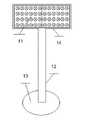
图2是本实用新型LED频闪警示装置在具体使用时的状态参考图。Fig. 2 is a reference diagram of the status of the LED strobe warning device of the present invention in specific use.
具体实施方式Detailed ways
下面结合说明书附图对本实用新型LED频闪警示装置作进一步说明。The LED strobe warning device of the present invention will be further described below in conjunction with the accompanying drawings of the description.
参见图1,555振荡电路1的输出端与D触发器2的输入端连接,D触发器2的Q端与555振荡电路3的输入端连接,D触发器2的 
参见图2,本实用新型LED频闪警示装置在具体使用时,频闪控制电路10放在盒体14中,红蓝LED闪光灯9嵌入在盒体14的一侧,盒体14的下端与喷塑灯杆12的上端连接,喷塑灯杆12的下端焊接有法轮盘13,法轮盘13与地面紧固。Referring to Fig. 2, when the utility model LED stroboscopic warning device is used specifically, the
本实用新型LED频闪警示装置的工作原理如下:The working principle of the utility model LED strobe warning device is as follows:
555振荡电路1作为D触发器2的时钟源,使D触发器2的Q端和
以上的实施例仅仅是对本实用新型的优选实施方式进行描述,并非对本实用新型的范围进行限定,在不脱离本实用新型设计精神的前提下,本领域普通工程技术人员对本实用新型的技术方案作出的各种变形和改进,均应落入本实用新型的权利要求书确定的保护范围内。The above embodiments only describe the preferred implementation of the utility model, and are not limiting the scope of the utility model. All variations and improvements should fall within the protection scope determined by the claims of the present utility model.
Claims (1)

Priority Applications (1)
| Application Number | Priority Date | Filing Date | Title |
|---|---|---|---|
| CN2010201359521UCN201858585U (en) | 2010-03-20 | 2010-03-20 | LED (light-emitting diode) stroboscopic warning device |
Applications Claiming Priority (1)
| Application Number | Priority Date | Filing Date | Title |
|---|---|---|---|
| CN2010201359521UCN201858585U (en) | 2010-03-20 | 2010-03-20 | LED (light-emitting diode) stroboscopic warning device |
Publications (1)
| Publication Number | Publication Date |
|---|---|
| CN201858585Utrue CN201858585U (en) | 2011-06-08 |
Family
ID=44104390
Family Applications (1)
| Application Number | Title | Priority Date | Filing Date |
|---|---|---|---|
| CN2010201359521UExpired - Fee RelatedCN201858585U (en) | 2010-03-20 | 2010-03-20 | LED (light-emitting diode) stroboscopic warning device |
Country Status (1)
| Country | Link |
|---|---|
| CN (1) | CN201858585U (en) |
Cited By (3)
| Publication number | Priority date | Publication date | Assignee | Title |
|---|---|---|---|---|
| CN105374293A (en)* | 2015-11-12 | 2016-03-02 | 成都格瑞思文化传播有限公司 | Flashing alarm board |
| CN109272811A (en)* | 2018-10-30 | 2019-01-25 | 魏长同 | A kind of double-colored exchange stroboscopic laser pen of teaching |
| CN109712472A (en)* | 2018-12-08 | 2019-05-03 | 魏磊 | A kind of page turning laser pen |
- 2010
- 2010-03-20CNCN2010201359521Upatent/CN201858585U/ennot_activeExpired - Fee Related
Cited By (3)
| Publication number | Priority date | Publication date | Assignee | Title |
|---|---|---|---|---|
| CN105374293A (en)* | 2015-11-12 | 2016-03-02 | 成都格瑞思文化传播有限公司 | Flashing alarm board |
| CN109272811A (en)* | 2018-10-30 | 2019-01-25 | 魏长同 | A kind of double-colored exchange stroboscopic laser pen of teaching |
| CN109712472A (en)* | 2018-12-08 | 2019-05-03 | 魏磊 | A kind of page turning laser pen |
Similar Documents
| Publication | Publication Date | Title |
|---|---|---|
| CN103501556B (en) | Double-color alternately flashing warning lights for municipal road safety construction | |
| CN201858585U (en) | LED (light-emitting diode) stroboscopic warning device | |
| CN203115765U (en) | Intelligent sensing street lamp | |
| CN204350351U (en) | A kind of full-automatic longitude and latitude controller for road lamp | |
| CN202791740U (en) | Light emitting diode (LED) rear combination lamp shiner | |
| CN206222268U (en) | The LED street lamp of infrared remote control can be carried out | |
| CN105702064A (en) | A kind of LED traffic light control method | |
| CN205152826U (en) | Luminous warning post of solar energy initiative | |
| CN201462421U (en) | Led caution light | |
| CN202916928U (en) | Multifunctional self-luminous warning belt | |
| CN201028298Y (en) | Multi-use portable safety warning lamp | |
| CN203215552U (en) | Warning lamp | |
| CN201251062Y (en) | Sidewalk LED lamp device | |
| CN209328223U (en) | Pedestrian and non-motor vehicle crossing the road monitoring and prompting device | |
| CN201045471Y (en) | Automatic flashing warning device for urban construction roadblocks | |
| CN102956169A (en) | Multi-functional automatic light-emitting warning tape | |
| CN205016040U (en) | Automatic alarm system of electric motor car bright lamp on daytime | |
| CN212036229U (en) | LED warning cap for road cleaning | |
| CN203821261U (en) | Sensitive traffic sign | |
| CN214311960U (en) | Thing networking warning light | |
| CN105090850B (en) | A kind of multifunctional unit LED lamp for vehicles | |
| CN218450605U (en) | Variable lane board and traffic light | |
| CN204285252U (en) | A kind of LED scene lamp | |
| CN203644350U (en) | An intelligent emergency parking warning light board | |
| CN2445387Y (en) | Multifuncltion musical flashing alarm light |
Legal Events
| Date | Code | Title | Description |
|---|---|---|---|
| C14 | Grant of patent or utility model | ||
| GR01 | Patent grant | ||
| CF01 | Termination of patent right due to non-payment of annual fee | Granted publication date:20110608 Termination date:20180320 | |
| CF01 | Termination of patent right due to non-payment of annual fee |