CN201858100U - Pneumatic pulse dosing pump - Google Patents
Pneumatic pulse dosing pumpDownload PDFInfo
- Publication number
- CN201858100U CN201858100UCN2010202418175UCN201020241817UCN201858100UCN 201858100 UCN201858100 UCN 201858100UCN 2010202418175 UCN2010202418175 UCN 2010202418175UCN 201020241817 UCN201020241817 UCN 201020241817UCN 201858100 UCN201858100 UCN 201858100U
- Authority
- CN
- China
- Prior art keywords
- pump chamber
- valve
- linear cylinder
- pump
- inlet
- Prior art date
- Legal status (The legal status is an assumption and is not a legal conclusion. Google has not performed a legal analysis and makes no representation as to the accuracy of the status listed.)
- Expired - Lifetime
Links
Images
Landscapes
- Structures Of Non-Positive Displacement Pumps (AREA)
Abstract
Translated fromChineseDescription
Translated fromChinese技术领域technical field
本实用新型涉及一种液体加入排出装置,具体为一种气动脉冲加药泵。 The utility model relates to a liquid adding and discharging device, in particular to a pneumatic pulse dosing pump. the
背景技术Background technique
传统的加药泵结构都是采用不锈钢叶轮旋转产生管道负压原理。由于不锈钢叶轮在工作过程中常常受到磨损或被腐蚀,因此必须经常检查、维修、更换叶轮,影响正常的加药工作,也影响到后续生产过程的一系列环节,给生产效率造成很大的影响。 The traditional dosing pump structure is based on the principle of negative pressure in the pipeline generated by the rotation of the stainless steel impeller. Since the stainless steel impeller is often worn or corroded during the working process, it is necessary to check, repair and replace the impeller frequently, which affects the normal dosing work and also affects a series of links in the subsequent production process, which has a great impact on production efficiency . the
因而,现有技术还有待于改进和提高。 Thereby, prior art still needs to improve and improve. the
实用新型内容Utility model content
本实用新型的目的在于克服以上问题,提供一种新型的加药泵。 The purpose of this utility model is to overcome the above problems and provide a novel dosing pump. the
本实用新型的技术方案包括: The technical scheme of the utility model comprises:
一种气动脉冲加药泵,其中,包括直线气缸、速度调节阀、双位进出电磁阀,泵室、泵室活塞、连杆、单向阀、流量调节阀;所述双位进出电磁阀通过两速度调节阀与直线气缸进气嘴相连;所述直线气缸活塞杆与泵室活塞杆由连杆相连,所述泵室下部设有进、排药管道,在进、排药管道上设有单 向阀及流量调节阀。 A pneumatic pulse dosing pump, which includes a linear cylinder, a speed regulating valve, a two-position in-out solenoid valve, a pump chamber, a pump chamber piston, a connecting rod, a one-way valve, and a flow regulating valve; the two-position in-out solenoid valve passes through The two-speed regulating valve is connected with the intake nozzle of the linear cylinder; the piston rod of the linear cylinder is connected with the piston rod of the pump chamber by a connecting rod, and the lower part of the pump chamber is provided with a drug inlet and discharge pipeline, and a drug inlet and discharge pipeline is provided with One-way valve and flow regulating valve. the
所述的气动脉冲加药泵,其中:所述的双向进出电磁阀设有进气口和电源接头。 The pneumatic pulse dosing pump, wherein: the two-way inlet and outlet solenoid valve is provided with an air inlet and a power connector. the
本实用新型产生的技术效果是: The technical effect that the utility model produces is:
本实用新型由于采用气动原理,电磁开关控制气泵泵室活塞运动产生负压,实现了对药液的吸入和排放,代替了不锈钢叶轮泵的功能,克服了传统不锈钢叶轮损坏或腐蚀造成的对生产的影响。 Because the utility model adopts the pneumatic principle, the electromagnetic switch controls the piston movement of the air pump pump chamber to generate negative pressure, realizes the suction and discharge of the liquid medicine, replaces the function of the stainless steel impeller pump, and overcomes the damage or corrosion of the traditional stainless steel impeller. Impact. the
附图说明Description of drawings
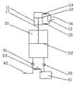
图1为本实用新型原理示意图。 Fig. 1 is the principle schematic diagram of the utility model. the
具体实施方式Detailed ways
以下结合附图实施例,说明本实用新型的结构原理如下: Below in conjunction with accompanying drawing embodiment, illustrate the structural principle of the present utility model as follows:
如图1所示,本实用新型气动脉冲加药泵包括直线气缸11、双速度调节阀14、15、双位进出电磁阀13,泵室21、泵室活塞22、连杆17、单向阀31、32、流量调节阀33。 As shown in Figure 1, the pneumatic pulse dosing pump of the utility model includes a
双位进出电磁阀13通过两速度调节阀14、15与直线气缸11的两端相连;电磁阀13为直线气缸11的动力装置,设有电池接线和进气口16。 The two-position in-out
直线气缸11活塞杆与泵室21活塞杆由连杆17相连,当直线气缸11的 活塞12上下移动时,带动泵室21的活塞22随之上下移动。
泵室21下部设有进、排药管道,单向阀31、32设置在进、排药管道上,两单向阀的接法相反,单向阀32的进入端接通往储药槽41的管道。流出端接泵室21的入口;单向阀31的进入端接泵室21排出口,流出端接药品输出口42。 The lower part of the
流量调节阀33设置在储药槽41与药品输出口42之间的管道上,用以将储药槽41中的药液排出。可根据实际需要灵活调节流量调节阀33,调节出药口出药量的大小,控制排放的速度。 The
本实用新型的工作过程如下: The working process of the present utility model is as follows:
接通电源,双位进出电磁阀13打开,通过电磁阀13控制直线气缸11运行,当直线气缸活塞12上行时,由连杆17带动泵室21的活塞22上行,使泵室21产生负压,过程中单向阀1(31)关闭,单向阀2(32)开启,储药槽中药品被吸入泵室21。当直线气缸活塞12在双位电磁阀13控制下下行时,单向阀2(32)关闭,单向阀1(31)开启,泵室21内药液排向药品输出口42,流量调节阀33设置在此管道上,根据需要通过调节流量阀门33调节药品输出量的大小。 Turn on the power, open the two-position in-out
本实用新型气动脉冲加药泵适用于污水处理、材料表面处理等强酸碱腐 蚀性溶液的输送或提升,解决传统不锈钢叶轮泵的损坏和腐蚀问题。 The utility model pneumatic pulse dosing pump is suitable for the transportation or lifting of strong acid and alkali corrosive solutions such as sewage treatment and material surface treatment, and solves the damage and corrosion problems of traditional stainless steel impeller pumps. the
综上所述,本实用新型气动脉冲加药泵采用气动原理实现了对药液的吸入和排放,代替了不锈钢叶轮泵的功能,克服了不锈钢叶轮损坏或腐蚀造成的对生产的影响,较好地实现了本实用新型的目的。 In summary, the pneumatic pulse dosing pump of the utility model realizes the suction and discharge of the liquid medicine by adopting the pneumatic principle, replaces the function of the stainless steel impeller pump, overcomes the impact on production caused by the damage or corrosion of the stainless steel impeller, and is better Realized the purpose of the utility model. the
应当理解的是,上述针对具体实施例的描述较为详细,并不能因此而认为是对本实用新型专利保护范围的限制,本实用新型的专利保护范围应以所附权利要求为准。 It should be understood that the above descriptions for specific embodiments are relatively detailed, and should not be considered as limiting the scope of protection of the patent of the utility model, and the scope of protection of the patent of the utility model should be based on the appended claims. the
Claims (2)
Translated fromChinesePriority Applications (1)
| Application Number | Priority Date | Filing Date | Title |
|---|---|---|---|
| CN2010202418175UCN201858100U (en) | 2010-06-28 | 2010-06-28 | Pneumatic pulse dosing pump |
Applications Claiming Priority (1)
| Application Number | Priority Date | Filing Date | Title |
|---|---|---|---|
| CN2010202418175UCN201858100U (en) | 2010-06-28 | 2010-06-28 | Pneumatic pulse dosing pump |
Publications (1)
| Publication Number | Publication Date |
|---|---|
| CN201858100Utrue CN201858100U (en) | 2011-06-08 |
Family
ID=44103908
Family Applications (1)
| Application Number | Title | Priority Date | Filing Date |
|---|---|---|---|
| CN2010202418175UExpired - LifetimeCN201858100U (en) | 2010-06-28 | 2010-06-28 | Pneumatic pulse dosing pump |
Country Status (1)
| Country | Link |
|---|---|
| CN (1) | CN201858100U (en) |
Cited By (6)
| Publication number | Priority date | Publication date | Assignee | Title |
|---|---|---|---|---|
| CN105525367A (en)* | 2016-02-17 | 2016-04-27 | 苏州经贸职业技术学院 | Electrostatic spinning pressure spray device simulating atrium and ventricle principle and electrostatic spinning system |
| CN106823079A (en)* | 2017-03-28 | 2017-06-13 | 上海方予健康医药科技有限公司 | A kind of quantitative atomized medicine introducing device of delivery type |
| CN106943811A (en)* | 2017-04-28 | 2017-07-14 | 合肥中亚环保科技有限公司 | A kind of electromagnetic poppet valves for sack cleaner |
| CN111991647A (en)* | 2014-06-25 | 2020-11-27 | 魏民 | Infusion device for administering a drug |
| CN112299551A (en)* | 2020-10-16 | 2021-02-02 | 合肥市恒昌自动化控制有限责任公司 | Phosphorus removal flocculating agent adding device |
| CN112919127A (en)* | 2021-01-19 | 2021-06-08 | 苏州诺亚智造科技有限公司 | Device for vacuum pipeline drainage |
- 2010
- 2010-06-28CNCN2010202418175Upatent/CN201858100U/ennot_activeExpired - Lifetime
Cited By (8)
| Publication number | Priority date | Publication date | Assignee | Title |
|---|---|---|---|---|
| CN111991647A (en)* | 2014-06-25 | 2020-11-27 | 魏民 | Infusion device for administering a drug |
| CN111991647B (en)* | 2014-06-25 | 2022-06-10 | 魏民 | Infusion device for administering a drug |
| CN105525367A (en)* | 2016-02-17 | 2016-04-27 | 苏州经贸职业技术学院 | Electrostatic spinning pressure spray device simulating atrium and ventricle principle and electrostatic spinning system |
| CN105525367B (en)* | 2016-02-17 | 2018-08-31 | 苏州经贸职业技术学院 | The electrostatic spinning pressure spray apparatus and electrostatic spinning system of imitative atrial ventricle principle |
| CN106823079A (en)* | 2017-03-28 | 2017-06-13 | 上海方予健康医药科技有限公司 | A kind of quantitative atomized medicine introducing device of delivery type |
| CN106943811A (en)* | 2017-04-28 | 2017-07-14 | 合肥中亚环保科技有限公司 | A kind of electromagnetic poppet valves for sack cleaner |
| CN112299551A (en)* | 2020-10-16 | 2021-02-02 | 合肥市恒昌自动化控制有限责任公司 | Phosphorus removal flocculating agent adding device |
| CN112919127A (en)* | 2021-01-19 | 2021-06-08 | 苏州诺亚智造科技有限公司 | Device for vacuum pipeline drainage |
Similar Documents
| Publication | Publication Date | Title |
|---|---|---|
| CN201858100U (en) | Pneumatic pulse dosing pump | |
| CN202768508U (en) | Hydraulic ram | |
| CN201331469Y (en) | High-pressure high-volume fatigue test system of pressure equipment | |
| CN204959727U (en) | Fluid level control formula steam and water separation device | |
| CN103306642B (en) | Numerical control and energy saving is without rod beam-pumping unit | |
| CN101782181A (en) | Non-contact pneumatic liquid energy-saving conveying device | |
| CN202001398U (en) | Pneumatic water pump | |
| CN202914411U (en) | Liquid pump drainage device of piston vacuum pump | |
| CN202138984U (en) | Portable circular pneumatic jack | |
| CN201730881U (en) | Vacuum pump | |
| CN202252162U (en) | Slowly-closing rubber flap check valve | |
| CN201916168U (en) | Pneumatic Diaphragm Pump High Suction Energy Saving Device | |
| CN201696306U (en) | Equal pressure and height difference water extraction device | |
| CN107605440B (en) | A pneumatic elastic oil production device for low-permeability and low-yield oil wells | |
| CN204113636U (en) | A kind of drawbench cooling pipe water suction device | |
| CN209876111U (en) | An automatic pressure regulating valve suitable for branch pipes | |
| CN203392497U (en) | Ore pulp high-concentration delivery system | |
| CN208236816U (en) | A kind of easy-cleaning type hydraulic power unit | |
| CN202811382U (en) | Device used for replacing self-priming pump to work | |
| CN201588260U (en) | A new type of water supply equipment | |
| CN202176478U (en) | Piston-type water pump | |
| CN205779636U (en) | High-pressure clear water pump gas extraction system | |
| CN209012033U (en) | A kind of new-type of hose pumping system | |
| CN202833341U (en) | Vacuum water taking device without pump | |
| CN201547039U (en) | A compressed gas single-acting actuator |
Legal Events
| Date | Code | Title | Description |
|---|---|---|---|
| C14 | Grant of patent or utility model | ||
| GR01 | Patent grant | ||
| CX01 | Expiry of patent term | ||
| CX01 | Expiry of patent term | Granted publication date:20110608 |