CN201837922U - Notebook computer - Google Patents
Notebook computerDownload PDFInfo
- Publication number
- CN201837922U CN201837922UCN2010206010610UCN201020601061UCN201837922UCN 201837922 UCN201837922 UCN 201837922UCN 2010206010610 UCN2010206010610 UCN 2010206010610UCN 201020601061 UCN201020601061 UCN 201020601061UCN 201837922 UCN201837922 UCN 201837922U
- Authority
- CN
- China
- Prior art keywords
- hook
- notebook computer
- pivot
- opening
- pivot shaft
- Prior art date
- Legal status (The legal status is an assumption and is not a legal conclusion. Google has not performed a legal analysis and makes no representation as to the accuracy of the status listed.)
- Expired - Fee Related
Links
- 239000002184metalSubstances0.000claimsabstractdescription59
- 238000010586diagramMethods0.000description11
- 230000007246mechanismEffects0.000description10
- 238000000034methodMethods0.000description3
- 230000007423decreaseEffects0.000description2
- 230000000694effectsEffects0.000description2
- 230000008569processEffects0.000description2
- 241000282414Homo sapiensSpecies0.000description1
- 230000001419dependent effectEffects0.000description1
- 230000004048modificationEffects0.000description1
- 238000012986modificationMethods0.000description1
- 230000004044responseEffects0.000description1
- 125000006850spacer groupChemical group0.000description1
Images


Landscapes
- Casings For Electric Apparatus (AREA)
Abstract
Description
Translated fromChinese技术领域technical field
本实用新型是有关于一种笔记本电脑,且特别是有关于一种具有使用可靠度的笔记本电脑。The utility model relates to a notebook computer, in particular to a notebook computer with reliability in use.
背景技术Background technique
在信息时代中,人类对于电子装置的依赖性与日俱增。应对现今电子产品的高速度、高效能及轻薄短小的要求,以笔记本电脑(Notebook PC)这种折叠式电子装置为例说明,已成为现代人生活及工作中不可或缺的应用工具。一般而言,笔记本电脑是由两个机体所组成,其中两机体的一侧是靠着一枢转机构相互连接,而两机体的另一侧则是应用卡扣来固定折叠后的两个机体的相对位置。In the information age, human beings are increasingly dependent on electronic devices. In response to the requirements of high speed, high performance, light weight and small size of today's electronic products, taking the notebook computer (Notebook PC) as an example to illustrate this foldable electronic device, it has become an indispensable application tool in modern people's life and work. Generally speaking, a notebook computer is composed of two bodies, one side of the two bodies is connected to each other by a pivot mechanism, and the other side of the two bodies is used to fix the folded two bodies relative position.
图1绘示已知一种笔记本电脑的示意图。请参考图1,笔记本电脑100的显示器110是借由枢转机构130与主机本体120连接。此外,显示器110上设置有卡扣机构140。当使用者将显示器110闭合于主机本体120时,卡扣机构140的卡钩142扣合于主机本体120的扣孔122中,以固定显示器110与主机本体120的相对位置。另外,当使用者欲开启笔记本电脑100时,使用者可以推移卡扣机构140的推钮144,连带地使与推钮144有连动关系的卡钩142脱离扣孔122的限制,而显示器110即与主机本体120分离。FIG. 1 shows a schematic diagram of a known notebook computer. Please refer to FIG. 1 , the
然而,由于上述的卡扣机构的卡钩是外露于显示器,因此当使用者在闭合笔记本电脑时须将卡钩扣合于扣孔时,卡钩容易受到不当碰撞而断裂,导致卡扣机构的可靠度不佳。如此一来,卡扣机构便无法有效地固定两折叠后的机体的相对位置。此外,外露于显示器的卡钩亦会影响笔记本电脑的整体外观。However, since the hook of the above-mentioned buckle mechanism is exposed to the display, when the user must fasten the hook to the button hole when closing the notebook computer, the hook is easily broken due to improper collision, resulting in the failure of the buckle mechanism. Not reliable. As a result, the buckle mechanism cannot effectively fix the relative positions of the two folded bodies. In addition, the hooks exposed on the display will also affect the overall appearance of the notebook computer.
实用新型内容Utility model content
本实用新型提供一种具有使用可靠度的笔记本电脑。The utility model provides a notebook computer with reliability in use.
本实用新型提出一种笔记本电脑,包括一第一机体、一第二机体、一枢接轴组、一金属卡勾、一限位件以及一磁性元件,第一机体具有一第一表面、一第二表面以及一贯孔,而贯孔贯穿第一表面及第二表面。第二机体具有朝向第一机体的一第三表面以及设置于第三表面的一开口,而枢接轴组连接于第一机体及第二机体之间,并位于第二机体远离开口的一侧,用以使第一机体相对第二机体开合及旋转。金属卡勾设置于第二机体的开口内,具有一枢接部以及一卡勾部,且枢接部枢接于第二机体,而卡勾部可以枢接部为轴心相对于第二机体旋转。限位件设置于贯孔内,限位件具有一本体以及二挡块,其中本体具有一容置槽,而挡块设置于本体,且限位件可于贯孔内滑动以使金属卡勾与其中一个挡块勾合。磁性元件设置于容置槽内。The utility model proposes a notebook computer, which includes a first body, a second body, a pivot shaft group, a metal hook, a limit piece and a magnetic element. The first body has a first surface, a The second surface and a through hole, and the through hole runs through the first surface and the second surface. The second body has a third surface facing the first body and an opening arranged on the third surface, and the pivot shaft group is connected between the first body and the second body and is located on the side of the second body away from the opening , for making the first body open, close and rotate relative to the second body. The metal hook is disposed in the opening of the second body, has a pivot portion and a hook portion, and the pivot portion is pivotally connected to the second body, and the hook portion can be relative to the second body with the pivot portion as the axis rotate. The limiter is arranged in the through hole. The limiter has a body and two stoppers. The body has a receiving groove, and the stopper is arranged on the body. The limiter can slide in the through hole to make the metal hook Engage with one of the stops. The magnetic element is arranged in the accommodating groove.
在本实用新型的笔记本电脑的一实施例中,上述的枢接轴组包括一第一枢接轴以及一第二枢接轴。第一枢接轴设置于第二机体远离开口的一侧或第一机体远离贯孔的一侧,以使第一机体及第二机体借由第一枢接轴套设,而第一枢接轴的轴向与第二机体的第三表面的法线方向垂直,以使第一机体可相对第二机体上下开合。第二枢接轴连接于第一机体远离贯孔的一侧以及第二机体远离开口的一侧,第二枢接轴的轴向与第二机体的法线方向平行,以使第一机体以第二枢接轴相对第二机体顺时针或逆时针旋转。In an embodiment of the notebook computer of the present invention, the pivotal shaft set includes a first pivotal shaft and a second pivotal shaft. The first pivot shaft is arranged on the side of the second body away from the opening or the side of the first body away from the through hole, so that the first body and the second body are sleeved by the first pivot shaft, and the first pivot The axial direction of the shaft is perpendicular to the normal direction of the third surface of the second body, so that the first body can be opened and closed up and down relative to the second body. The second pivot shaft is connected to the side of the first body away from the through hole and the side of the second body away from the opening, the axial direction of the second pivot shaft is parallel to the normal direction of the second body, so that the first body The second pivot shaft rotates clockwise or counterclockwise relative to the second body.
在本实用新型的笔记本电脑的一实施例中,上述的金属卡勾的卡勾部具有一第一导引斜面,而每一挡块具有一第二导引斜面,且第二导引斜面用以与第一导引斜面接触并导引金属卡勾的卡勾部与其中一个挡块勾合。In an embodiment of the notebook computer of the present utility model, the hook part of the above-mentioned metal hook has a first guiding slope, and each block has a second guiding slope, and the second guiding slope is used to Engage with one of the stoppers by contacting with the first guiding slope and guiding the hook portion of the metal hook.
在本实用新型的笔记本电脑的一实施例中,上述的挡块对称设置。In an embodiment of the notebook computer of the present invention, the above-mentioned stoppers are arranged symmetrically.
在本实用新型的笔记本电脑的一实施例中,更包括两第一弹性件,且每一第一弹性件的两端分别连接于限位件的其中一端以及第一机体之间。In an embodiment of the notebook computer of the present invention, it further includes two first elastic members, and two ends of each first elastic member are respectively connected between one end of the limiting member and the first body.
在本实用新型的笔记本电脑的一实施例中,更包括一第二弹性件,连接于第二机体及枢接部之间,用以使金属卡勾复位。In an embodiment of the notebook computer of the present invention, it further includes a second elastic member, which is connected between the second body and the pivot joint, and is used to reset the metal hook.
在本实用新型的笔记本电脑的一实施例中,更包括与限位件连接的一推钮,且推移推钮以带动限位件以解除限位件与金属卡勾的勾合。In an embodiment of the notebook computer of the present invention, it further includes a push button connected to the limiting member, and the pushing button is pushed to drive the limiting member to release the engagement between the limiting member and the metal hook.
基于上述,本实用新型的笔记本电脑的第一机体内设置有磁性元件,且当第一机体相对靠近第二机体时,磁性元件的磁力吸引金属卡勾的卡勾部以枢接部为轴心旋转以与枢接件的枢接部勾合。当第一机体相对远离第二机体时,磁性元件的磁力渐小,让金属卡勾的卡勾部以枢接部为轴心旋转以回复至开口内。对于使用者来说,使用者不需要以手动的方式便能使金属卡勾内藏于第二机体中,而是借由磁性元件的磁力让金属卡勾突出于开口之外,所以不会有机体与金属卡勾碰撞而造成损坏的情形发生,具有使用可靠度。Based on the above, the first body of the notebook computer of the present invention is provided with a magnetic element, and when the first body is relatively close to the second body, the magnetic force of the magnetic element attracts the hook portion of the metal hook with the pivot portion as the axis Rotate to engage with the pivot joint of the pivot joint. When the first body is relatively far away from the second body, the magnetic force of the magnetic element gradually decreases, so that the hook portion of the metal hook rotates around the pivot portion to return to the opening. For the user, the user does not need to manually hide the metal hook in the second body, but uses the magnetic force of the magnetic element to make the metal hook protrude out of the opening, so there will be no organic body Collision with the metal hook will cause damage, which is reliable in use.
附图说明Description of drawings
为让本实用新型的上述目的、特征和优点能更明显易懂,以下结合附图对本实用新型的具体实施方式作详细说明,其中:In order to make the above-mentioned purposes, features and advantages of the utility model more obvious and easy to understand, the specific implementation of the utility model will be described in detail below in conjunction with the accompanying drawings, wherein:
图1绘示已知一种笔记本电脑的示意图。FIG. 1 shows a schematic diagram of a known notebook computer.
图2为本实用新型一实施例的笔记本电脑的第一机体相对第二机体打开的示意图。FIG. 2 is a schematic diagram of the first body of the notebook computer opened relative to the second body according to an embodiment of the present invention.
图3为图2的笔记本电脑的第一机体与第二机体相对闭合且金属卡勾勾合于限位件的局部示意图。FIG. 3 is a partial schematic diagram of the first body and the second body of the notebook computer in FIG. 2 being closed relative to each other and the metal hook hooked to the limiting member.
图4为图3的金属卡勾的卡勾部突出于第二机体的开口的示意图。FIG. 4 is a schematic diagram of the hook portion of the metal hook in FIG. 3 protruding from the opening of the second body.
图5~图8为将图2的笔记本电脑的第一机体与第二机体相对固定的作动流程图。FIGS. 5-8 are flow charts for relatively fixing the first body and the second body of the notebook computer in FIG. 2 .
图9为图2的笔记本电脑的局部示意图。FIG. 9 is a partial schematic diagram of the notebook computer in FIG. 2 .
图10为第一机体的第一表面朝外时,金属卡勾与限位件相互勾合的示意图。FIG. 10 is a schematic diagram of the metal hook engaging with the limiting member when the first surface of the first body faces outward.
主要元件符号说明:Description of main component symbols:
100:笔记本电脑100: Laptop
110:显示器110: display
120:主机本体120: host body
122:扣孔122: buttonhole
130:枢转机构130: pivot mechanism
140:卡扣机构140: buckle mechanism
142:卡钩142: Hook
144:推钮144: push button
200:笔记本电脑200: Laptop
210:第一机体210: The first body
212:第一表面212: First Surface
214:第二表面214: second surface
216:贯孔216: through hole
220:第二机体220: Second body
222:第三表面222: Third Surface
224:开口224: opening
230:枢接轴组230: Pivot shaft group
232:第一枢接轴232: First pivot axis
234:第二枢接轴234: Second pivot axis
240:金属卡勾240: metal hook
242:枢接部242: pivot joint
244:卡勾部244: Hook Department
244a:第一导引斜面244a: first guide bevel
250:限位件250: Limiting parts
252:本体252: Ontology
252a:容置槽252a: storage tank
254a、254b:挡块254a, 254b: stoppers
254c、254d:第二导引斜面254c, 254d: the second guide slope
260:磁性元件260: Magnetic components
270:第一弹性件270: first elastic member
280:推钮280: push button
290:第二弹性件290: second elastic member
W1:宽度方向的中心假想线W1: Center imaginary line in the width direction
L1:长度方向的中心假想线L1: Center imaginary line in the length direction
C:交会中心C: Rendezvous Center
X1、X2:轴向X1, X2: Axial
N:法线方向N: normal direction
具体实施方式Detailed ways
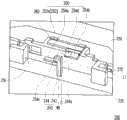
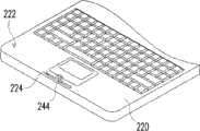
图2为本实用新型一实施例的笔记本电脑的第一机体相对第二机体打开的示意图、图3为图2的笔记本电脑的第一机体与第二机体相对闭合且金属卡勾勾合于限位件的局部示意图,而图4为图3的金属卡勾的卡勾部突出于第二机体的开口的示意图。请同时参考图2、图3及图4,笔记本电脑200包括一第一机体210、一第二机体220、一枢接轴组230、一金属卡勾240、一限位件250以及一磁性元件260。第一机体210具有一第一表面212、一第二表面214以及一贯孔216,其中第二表面214与第一表面212相对,而贯孔216贯穿第一表面212及第二表面214。第二机体220具有朝向第一机体210的一第三表面222以及设置于第三表面222的一开口224。枢接轴组230连接于第一机体210及第二机体220之间,并位于第二机体220远离开口224的一侧,以使第一机体210可以相对第二机体220做开合及顺时针或逆时针旋转的动作。金属卡勾240设置于第二机体220的开口224内,此金属卡勾240具有一枢接部242以及一卡勾部244,且枢接部242枢接于第二机体220,而卡勾部244可以枢接部242为轴心相对于第二机体220旋转以突出于开口224(如图4示)或收纳于第二机体220内。限位件250设置于第一机体210的贯孔216内,限位件250具有一本体252以及二挡块254a、254b,其中本体252具有一容置槽252a,而挡块254a、254b设置于本体252的同一侧面,且限位件250可于第一机体210的贯孔216内滑动以使金属卡勾240与其中一个挡块254a(或254b)勾合,以固定第一机体210第二机体220的相对位置。磁性元件260设置于限位件250的本体252的容置槽252a内,且磁性元件260用以提供磁力以吸引金属卡勾240的卡勾部244以枢接部242为轴心旋转而突出于开口224(如图4示)。Fig. 2 is a schematic diagram of the opening of the first body of the notebook computer relative to the second body of the notebook computer according to an embodiment of the present invention; Fig. 3 is a diagram of the first body and the second body of the notebook computer of Fig. 4 is a schematic diagram of the hook portion of the metal hook in FIG. 3 protruding from the opening of the second body. Please refer to FIG. 2 , FIG. 3 and FIG. 4 at the same time. The
详细而言,枢接轴组230包括一第一枢接轴232以及一第二枢接轴234。第一枢接轴232设置于第二机体220远离开口224的一侧(即第二机体220未设置有开口224的相对侧)或第一机体210远离贯孔216的一侧(即第一机体210未设置有贯孔216的相对侧),其中第一机体210及第二机体220借由第一枢接轴232互相套设,而第一枢接轴232的轴向X1与第二机体220的第三表面222的法线方向N互相垂直,所以第一机体210借由第一枢接轴232而可以相对第二机体220上下开合。第二枢接轴234连接于第一机体210远离贯孔216的一侧以及第二机体220远离开口224的一侧,其中第二枢接轴234的轴向X2与第二机体220的法线方向N平行,所以第一机体210可以第二枢接轴234相对第二机体220顺时针或逆时针旋转。In detail, the pivot shaft set 230 includes a
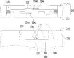
此外,承上述,金属卡勾240的卡勾部244具有一第一导引斜面244a,而挡块254a、254b分别具有一第二导引斜面254c、254d,且第二导引斜面254c、254d用以与第一导引斜面244a接触并导引金属卡勾240的卡勾部244与挡块254a(或挡块254b)勾合。附带一提,由于本实施例的第一机体210可以先相对第二机体220开启,两个挡块254a、254b是在限位件250的本体252上对称地设置。此处的对称是指假想限位件250的本体252具有位于其长度方向及宽度方向的中心假想线L1、W1,挡块254a以假想线L1为中心线上、下镜射后,再以假想线W1为中心线左、右镜射,挡块254a的位置与形状会与挡块254b完全重合。又或者,限位件250的本体252具有长度方向及宽度方向的假想线的交会中心C,且限位件250以此交会中心C为旋转中心旋转180度,旋转后的挡块254a的位置及形状会与旋转前的挡块254b的位置及形状完全重合,而旋转后的挡块254b的位置及形状会与旋转前的挡块254a的位置及形状完全重合。In addition, according to the above, the
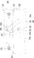
图5~图8为将图2的笔记本电脑的第一机体与第二机体相对固定的作动流程图。首先请同时参考图2及图5,借由第一枢轴232以将第一机体210相对第二机体220打开,此时,第一机体210的第一表面212相对面向第二机体220,而第二表面214相对朝外,且金属卡勾240躺置于第二机体220内。接着请同时参考图3及图6,当使用者施力将第一机体210设置有贯孔216的该侧往靠近第二机体220的方向渐渐移动时,磁性元件260也随着越来越靠近金属卡勾240。在磁性元件260的磁力开始对金属卡勾240产生作用时,金属卡勾240的卡勾部244会以枢接部242为轴心而逆时针旋转,卡勾部244突出于第二机体220的开口224之外。FIGS. 5-8 are flow charts for relatively fixing the first body and the second body of the notebook computer in FIG. 2 . First, please refer to FIG. 2 and FIG. 5 at the same time. The
接着如图7示,设置在本体252的挡块254a的第二导引斜面254c会与金属卡勾240的卡勾部244的第一导引斜面244a接触,以让第一导引斜面244a沿着第二导引斜面254c移动,进而导引金属卡勾240的卡勾部244与挡块254a勾合,如图8示。附带说明的是,由于限位件250是可相对第一机体210滑动,其中限位件250及第一机体210可以是借由滑槽及设置于滑槽中的凸条的形式以达成限位件250相对第一机体210滑动,所以在施力使第一机体210相对靠近第二机体220且第一导引斜面244a接触第二导引斜面254c时,限位件250可受到金属卡勾240的卡勾部244的第一导引斜面244a的推移而稍稍相对第一机体210移动。Next, as shown in FIG. 7 , the
为了让金属卡勾240的卡勾部244与限位件250的挡块254的勾合面积更多以维持良好的勾合效果,笔记本电脑200可更包括两个第一弹性件270,且每一第一弹性件270的两端分别连接于限位件250的其中一端以及第一机体210之间。如此,在限位件250相对第一机体210稍微移动后,第一弹性件270的弹性恢复力会使限位件250回复至原本的位置。In order to increase the hooking area between the hooking
图9为图2的笔记本电脑的局部示意图。请参考图9,笔记本电脑200可更包括与限位件250连接的一推钮280,且图9中的推钮280是设置在第一机体210的第一表面212上,而在其他未绘示的实施例中,也可以是设置在第二表面214或连接于第一表面212及第二表面214之间的一第三表面(未标示)上,依照需求决定。而此推钮280用以推移限位件250以解除限位件250与金属卡勾240的勾合,之后使用者便可以再将第一机体210相对第二机体220打开。FIG. 9 is a partial schematic diagram of the notebook computer in FIG. 2 . Please refer to FIG. 9, the
在使用者将第一机体210相对第二机体220打开的时候,如同图5至图8的反序,解除限位件250与金属卡勾240的勾合后,使用者推移第一机体210相对第二机体220打开,而随着第一机体210的一侧相对远离第二机体220,磁性元件260的磁力对于金属卡勾240的吸引作用也降低,甚至无。本实施例的笔记本电脑200可更包括一第二弹性件290,其为弹簧,且连接于第二机体220及金属卡勾240的枢接部242之间。当磁性元件260的磁力对于金属卡勾240的吸引作用力小于第二弹性件290的弹性恢复力时,第二弹性件290的弹性恢复力使金属卡勾240的卡勾部244以枢接部242为轴心旋转复位,金属卡勾240的卡勾部244旋回开口224内,金属卡勾240躺置于第二机体220内。第二弹性件290的两端也可以是连接在第二机体220及卡勾部244,依照需求决定。When the user opens the
之后可如图2示,使第一机体210以第二枢轴234为轴心顺时针或逆时针旋转,以使原本朝外的第二表面214相对朝向第二机体220,而原本朝向第二机体220的第一表面212相对朝外,然后再依照图5至图8的顺序,使金属卡勾240的卡勾部244与限位件250的挡块254b互相勾合,如图10示。使金属卡勾240的卡勾部244与限位件250的挡块254b互相勾合的流程与上述的图5至图8的勾合流程描述相类似,因此不再详细描述。Afterwards, as shown in FIG. 2 , the
综上所述,本实用新型的笔记本电脑的第一机体内的磁性元件可以在第一机体相对靠近第二机体时提供磁力以吸引金属卡勾,使金属卡勾的卡勾部以枢接部为轴心旋转以突出于开口之外,并与枢接件的枢接部勾合。当第一机体相对远离第二机体时,磁性元件的磁力渐小,让金属卡勾的卡勾部以枢接部为轴心旋转以回复至开口内。对于使用者来说,借由磁性元件的磁力,使用者不需要以手动的方式便能使金属卡勾突出于开口之外或是内藏于第二机体中,所以不会有机体与金属卡勾碰撞而造成损坏的情形发生,具有使用可靠度。再者,使用者只有在解除金属卡勾与限位件的限位时才需要用手操作,而使金属卡勾突出于开口之外或旋转回复至第二机体内,都不需要用手操作,所以本实用新型的笔记本电脑还具有使用便利性。To sum up, the magnetic element in the first body of the notebook computer of the present invention can provide magnetic force to attract the metal hook when the first body is relatively close to the second body, so that the hook portion of the metal hook can be connected with the pivot joint. The shaft is rotated to protrude from the opening, and engages with the pivot joint of the pivot joint. When the first body is relatively far away from the second body, the magnetic force of the magnetic element gradually decreases, so that the hook portion of the metal hook rotates around the pivot portion to return to the opening. For the user, with the help of the magnetic force of the magnetic element, the user does not need to manually make the metal hook protrude from the opening or be hidden in the second body, so there will be no organic body and the metal hook The situation of damage caused by collision occurs, and it has reliability in use. Furthermore, the user only needs to operate by hand when releasing the metal hook and the limiter, and the metal hook protrudes out of the opening or rotates back into the second body without manual operation , so the notebook computer of the present utility model also has convenience of use.
虽然本实用新型已以较佳实施例揭示如上,然其并非用以限定本实用新型,任何本领域技术人员,在不脱离本实用新型的精神和范围内,当可作些许的修改和完善,因此本实用新型的保护范围当以权利要求书所界定的为准。Although the present utility model has been disclosed above with preferred embodiments, it is not intended to limit the present utility model. Any person skilled in the art may make some modifications and improvements without departing from the spirit and scope of the present utility model. Therefore, the protection scope of the present utility model should be defined by the claims.
Claims (7)
Translated fromChinesePriority Applications (1)
| Application Number | Priority Date | Filing Date | Title |
|---|---|---|---|
| CN2010206010610UCN201837922U (en) | 2010-11-02 | 2010-11-02 | Notebook computer |
Applications Claiming Priority (1)
| Application Number | Priority Date | Filing Date | Title |
|---|---|---|---|
| CN2010206010610UCN201837922U (en) | 2010-11-02 | 2010-11-02 | Notebook computer |
Publications (1)
| Publication Number | Publication Date |
|---|---|
| CN201837922Utrue CN201837922U (en) | 2011-05-18 |
Family
ID=44008025
Family Applications (1)
| Application Number | Title | Priority Date | Filing Date |
|---|---|---|---|
| CN2010206010610UExpired - Fee RelatedCN201837922U (en) | 2010-11-02 | 2010-11-02 | Notebook computer |
Country Status (1)
| Country | Link |
|---|---|
| CN (1) | CN201837922U (en) |
Cited By (1)
| Publication number | Priority date | Publication date | Assignee | Title |
|---|---|---|---|---|
| US9851745B2 (en) | 2012-09-12 | 2017-12-26 | Hewlett-Packard Development Company, L.P. | Latch for a computer case |
- 2010
- 2010-11-02CNCN2010206010610Upatent/CN201837922U/ennot_activeExpired - Fee Related
Cited By (1)
| Publication number | Priority date | Publication date | Assignee | Title |
|---|---|---|---|---|
| US9851745B2 (en) | 2012-09-12 | 2017-12-26 | Hewlett-Packard Development Company, L.P. | Latch for a computer case |
Similar Documents
| Publication | Publication Date | Title |
|---|---|---|
| CN102681606B (en) | Portable electronic device | |
| TWI387425B (en) | Latch mechanism and portable computer | |
| CN101959379B (en) | Electronic equipment and blocking device thereof | |
| TWI438609B (en) | Two-way latch mechanism and related electronic device | |
| TWI364647B (en) | Overturning cover mechanism and electronic device using the same | |
| CN104936388B (en) | Panel structure, electronic device shell and electronic device | |
| CN103576768A (en) | Expansion platform of portable electronic device | |
| CN106155196B (en) | Clamping device and electronic device | |
| CN103313565B (en) | Snap mechanism | |
| CN107368148B (en) | Supporting mechanism and portable electronic device | |
| TW201342024A (en) | Switch module for activating a hibernation mode of an electronic device and eletronic device therewith | |
| TW201240567A (en) | Electronic device with an adjustable board structure | |
| JP4137109B2 (en) | Sliding latch mechanism | |
| CN202443359U (en) | Sliding connector mechanism and related thin portable electronic device | |
| CN201837922U (en) | Notebook computer | |
| TW201308782A (en) | Connector mechanism for connecting a terminal | |
| CN102465641B (en) | Latch mechanism and portable computer | |
| CN102759986B (en) | Computer peripheral device capable of being fixed on casing of portable computer | |
| TWI571194B (en) | Electronic device assembly and dock thereof | |
| TW202122957A (en) | Foldable electronic device | |
| CN111664155B (en) | Positioning module and electronic device | |
| CN101211196A (en) | Folding electronic device | |
| CN103779725B (en) | Guide module and electronic device using it | |
| CN101754632A (en) | Clamping module and portable electronic device | |
| TWM400020U (en) | Notebook computer |
Legal Events
| Date | Code | Title | Description |
|---|---|---|---|
| C14 | Grant of patent or utility model | ||
| GR01 | Patent grant | ||
| CF01 | Termination of patent right due to non-payment of annual fee | Granted publication date:20110518 Termination date:20191102 | |
| CF01 | Termination of patent right due to non-payment of annual fee |