CN201817802U - Ocean platform hydraulic lifting device - Google Patents
Ocean platform hydraulic lifting deviceDownload PDFInfo
- Publication number
- CN201817802U CN201817802UCN2010201491760UCN201020149176UCN201817802UCN 201817802 UCN201817802 UCN 201817802UCN 2010201491760 UCN2010201491760 UCN 2010201491760UCN 201020149176 UCN201020149176 UCN 201020149176UCN 201817802 UCN201817802 UCN 201817802U
- Authority
- CN
- China
- Prior art keywords
- hydraulic cylinder
- main hydraulic
- lifting main
- cylinder
- spud leg
- Prior art date
- Legal status (The legal status is an assumption and is not a legal conclusion. Google has not performed a legal analysis and makes no representation as to the accuracy of the status listed.)
- Expired - Lifetime
Links
- 238000005086pumpingMethods0.000claimsdescription9
- 238000005265energy consumptionMethods0.000abstractdescription4
- 230000000630rising effectEffects0.000description4
- 230000007423decreaseEffects0.000description3
- 238000000034methodMethods0.000description3
- 238000005516engineering processMethods0.000description2
- 230000002457bidirectional effectEffects0.000description1
- 230000003139buffering effectEffects0.000description1
- 238000010276constructionMethods0.000description1
- 239000012530fluidSubstances0.000description1
- 239000000446fuelSubstances0.000description1
- 230000002452interceptive effectEffects0.000description1
Images
Landscapes
- Types And Forms Of Lifts (AREA)
Abstract
Description
Technical field:
The utility model relates to the self-action offshore platform lifting gear of ocean engineering, relates in particular to the ocean platform hydraulic lift.
Background technology:
The self lift type offshore platform is the packaged type offshore boring island of setting up in the marine site, and it is inserted the seabed and supported platform by spud leg and leaves the sea level certain altitude, carries out the exploration and the exploitation work of offshore oil.The self-elevating ocean platform jacking system can realize that spud leg vertically is inserted into the precalculated position, seabed, and lifting platform main body again makes it to rise to along spud leg and leaves the sea level certain height, to avoid the impact of wave to main platform body; Also can fall platform earlier, rise spud leg again and carry out towage.But the mechanical type or the hydraulic lifting device operating efficiency that are provided with on four angles of traditional close spud leg are not high, the apparatus structure complexity, and the energy consumption height, operation is inconvenience also.
The utility model content:
The purpose of this utility model provides the ocean platform hydraulic lift, and it can be increased work efficiency effectively, and is simple for structure, easily manufactured, and reliable operation has reduced energy consumption, and adopts Automatic Control.
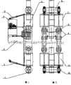
In order to solve the existing problem of background technology, the utility model is by the following technical solutions: it is made up of spud leg 1, push-and-pullhydraulic cylinder 2,platform 3, hydraulicpower pumping plant 4,spud leg breach 5, upper beam 6, last lifting main hydraulic cylinder 7,central sill 8, cylinder body bearingpin 9,underbeam 10 and following lifting mainhydraulic cylinder 11,platform 3 is near lifting main hydraulic cylinder 7 and following lifting mainhydraulic cylinder 11 are set on four angles of spud leg 1, its in pairs, symmetric arrangement up and down; Be provided with cylinder body bearingpin 9 between last lifting main hydraulic cylinder 7 and the following lifting mainhydraulic cylinder 11; Be provided withcentral sill 8 between the cylinder body bearingpin 9; Upper beam 6 is hinged between the piston rod of lifting main hydraulic cylinder 7, andunderbeam 10 is hinged on down between the piston rod of lifting mainhydraulic cylinder 11; One end of last lifting main hydraulic cylinder 7 and following lifting mainhydraulic cylinder 11 links to each other with an end of push-and-pullhydraulic cylinder 2; The arranged outside of last lifting main hydraulic cylinder 7 has hydraulicpower pumping plant 4; Have spud leg breach 5 on four seamed edges of spud leg 1.
Described hydraulicpower pumping plant 4 is by controller and central control room control on the spot.
The described lifting main hydraulic cylinder 7 of going up can rotate around cylinder body bearingpin 9 with following lifting mainhydraulic cylinder 11, change, produce the breach on the spud leg 1 over to by switching upper beam 6, theunderbeam 10 gone up between lifting main hydraulic cylinder 7, the following lifting mainhydraulic cylinder 11, and " quasi-continuous " lifting that realizes spud leg 1 orplatform 3 by the synchronization telescope of last lifting main hydraulic cylinder 7, following lifting mainhydraulic cylinder 11.
Spudleg breach 5 is advanced in the translation when finishing lifting of describedcentral sill 8, supports spud leg 1 orplatform 3 weight, makes the hydraulic system off-load, and hydraulic cylinder is all withdrawn.
The utility model has the advantages that simple in structure, reliable operation, energy consumption is low, can increase work efficiency effectively.
Description of drawings:
Fig. 1 is a structural representation of the present utility model;
Fig. 2 is the right view of Fig. 1.
The specific embodiment:
With reference to Fig. 1-2, this specific embodiment is by the following technical solutions: it by spud leg 1, push-and-pullhydraulic cylinder 2,platform 3, hydraulicpower pumping plant 4,spud leg breach 5, put the beams in place 6, go up lifting main hydraulic cylinder 7,central sill 8, cylinder body bearingpin 9,underbeam 10 and following lifting mainhydraulic cylinder 11 and form,platform 3 is near lifting main hydraulic cylinder 7 and following lifting mainhydraulic cylinder 11 are set on four angles of spud leg 1, its in pairs, symmetric arrangement up and down; Be provided with cylinder body bearingpin 9 between last lifting main hydraulic cylinder 7 and the following lifting mainhydraulic cylinder 11; Be provided withcentral sill 8 between the cylinder body bearingpin 9; Upper beam 6 is hinged between the piston rod of lifting main hydraulic cylinder 7, andunderbeam 10 is hinged on down between the piston rod of lifting mainhydraulic cylinder 11; One end of last lifting main hydraulic cylinder 7 and following lifting mainhydraulic cylinder 11 links to each other with an end of push-and-pullhydraulic cylinder 2; The arranged outside of last lifting main hydraulic cylinder 7 has hydraulicpower pumping plant 4; Have spud leg breach 5 on four seamed edges of spud leg 1.
Described hydraulicpower pumping plant 4 is by controller and central control room control on the spot.
The described lifting main hydraulic cylinder 7 of going up can rotate around cylinder body bearingpin 9 with following lifting mainhydraulic cylinder 11, change, produce the breach on the spud leg 1 over to by switching upper beam 6, theunderbeam 10 gone up between lifting main hydraulic cylinder 7, the following lifting mainhydraulic cylinder 11, and " quasi-continuous " lifting that realizes spud leg 1 orplatform 3 by the synchronization telescope of last lifting main hydraulic cylinder 7, following lifting mainhydraulic cylinder 11.
Spudleg breach 5 is advanced in the translation when finishing lifting of describedcentral sill 8, supports spud leg 1 orplatform 3 weight, makes the hydraulic system off-load, and hydraulic cylinder is all withdrawn.
This specific embodiment is to handle upper and lower beam by the synchronization telescope of upper and lower main hydraulic cylinder and push-and-pull hydraulic cylinder to pass in and out the lifting that the spud leg breach is realized spud leg or platform in certain sequence.The spud leg breach is advanced in the central sill translation when finishing lifting, supports spud leg or platform weight, makes the hydraulic system off-load, and hydraulic cylinder is all withdrawn.Lifting process specifically is divided into four operating modes: spud leg descends, platform rises, platform descends, spud leg rises; Each operating mode comprises eight step prefaces as an actuation cycle, finishes the rising or the decline of a pitch (1600mm).
1, spud leg decline operating mode
(1) cylinder contracts to full reduced (0mm) down, and underbeam supports spud leg, and upper cylinder half contracts to full reduced (0mm) to meta again, the unloading of putting the beams in place;
(2) underbeam supports spud leg, and the upper beam meta produces;
(3) cylinder extends 800mm synchronously down, and upper cylinder half extends 800mm;
(4) underbeam supports spud leg, puts the beams in place to change meta over to;
(5) upper cylinder half extends entirely and stretches (850mm), puts the beams in place and supports spud leg, plays cylinder to extend entirely again and stretches (850mm) to meta, the underbeam unloading;
(6) upper beam supports spud leg, and the underbeam meta produces;
(7) upper cylinder half contracts synchronously to 50mm, and following cylinder contracts to 50mm;
(8) upper beam supports spud leg, and underbeam changes meta over to.
2, platform rising operating mode
(1) upper beam support platform, underbeam changes meta over to;
(2) cylinder extends 50mm down, the underbeam support platform, and upper cylinder half extends 50mm to meta again, the unloading of putting the beams in place;
(3) underbeam support platform, the upper beam meta produces;
(4) cylinder extends entirely synchronously and stretches (850mm) under, and upper cylinder half extends entirely stretches (850mm);
(5) underbeam support platform, putting the beams in place changes meta over to;
(6) upper cylinder half contracts to 800mm upper beam support platform, plays cylinder to contract to 800mm to meta again, the underbeam unloading;
(7) upper beam support platform, the underbeam meta produces;
(8) upper cylinder half contracts synchronously to full reduced (0mm), and following cylinder contracts to full reduced (0mm).
3, platform decline operating mode
(1) upper cylinder half contracts to full reduced (0mm), and the upper beam support platform plays cylinder to contract to full reduced (0mm) to meta the underbeam off-load again;
(2) upper beam support platform, the underbeam meta produces;
(3) upper cylinder half extends 800mm synchronously, and following cylinder extends 800mm;
(4) upper beam support platform, underbeam changes meta over to;
(5) cylinder extends entirely and stretches (850mm) under, the underbeam support platform, and upper cylinder half extends entirely and stretches (850mm) to meta again, the unloading of putting the beams in place;
(6) underbeam support platform, the upper beam meta produces;
(7) cylinder contracts synchronously to 50mm down, and upper cylinder half contracts to 50mm;
(8) underbeam support platform, putting the beams in place changes meta over to.
4, spud leg rising operating mode
(1) underbeam supports spud leg, puts the beams in place to change meta over to;
(2) upper cylinder half extends 50mm, puts the beams in place and supports spud leg, plays cylinder to extend 50mm to meta again, the underbeam unloading;
(3) upper beam supports spud leg, and the underbeam meta produces;
(4) upper cylinder half extends entirely synchronously and stretches (850mm), and following cylinder extends entirely stretches (850mm);
(5) upper beam supports spud leg, and underbeam changes meta over to;
(6) cylinder contracts to 800mm down, and underbeam supports spud leg, and upper cylinder half contracts to 800mm to meta again, the unloading of putting the beams in place.
(7) underbeam supports spud leg, and the upper beam meta produces;
(8) cylinder contracts synchronously to full reduced (0mm) down, and upper cylinder half contracts to full reduced (0mm).
The advantage of this specific embodiment is to adopt two groups of cylinders, the girder construction of upper and lower symmetric arrangement to stretch the cylinder or the cylinder that contracts simultaneously, can realize " quasi-continuous " lifting of spud leg or platform, shortens closely in half at the cylinder stroke, effectively increases work efficiency; Cylinder, beam change, produce the spud leg breach over to and realize lifting about adopting, and make system architecture succinct, and be stressed clear and definite, easily manufactured, reliable operation; Two main hydraulic cylinders fuel feeding in parallel was realized the stress equalization of beam about the lifting hydraulic system was taked; The oil return of taking to descend utilizes measure to improve fluid utilization rate and rising or falling speed, cuts down the consumption of energy; Adopt the locking and the bidirectional buffering effect of equalizing valve, make spud leg or platform be subjected to realize steady, reliable lifting when stormy waves impacts; The computer network man-machine interactive system is carried out whole process supervision, automatically realizes the functions such as synchronization lifting, load equilibrium, attitude rectification, operation locking, process demonstration and fault alarm of spud leg or platform.
Claims (3)
1. ocean platform hydraulic lift, it is characterized in that it by spud leg (1), push-and-pull hydraulic cylinder (2), platform (3), hydraulic power pumping plant (4), spud leg breach (5), put the beams in place (6), go up lifting main hydraulic cylinder (7), central sill (8), cylinder body bearing pin (9), underbeam (10) and following lifting main hydraulic cylinder (11) and form, platform (3) is provided with lifting main hydraulic cylinder (7) and following lifting main hydraulic cylinder (11) near on four angles of spud leg (1), its in pairs, symmetric arrangement up and down; Be provided with cylinder body bearing pin (9) between last lifting main hydraulic cylinder (7) and the following lifting main hydraulic cylinder (11); Be provided with central sill (8) between the cylinder body bearing pin (9); Upper beam (6) is hinged between the piston rod of lifting main hydraulic cylinder (7), and underbeam (10) is hinged on down between the piston rod of lifting main hydraulic cylinder (11); One end of last lifting main hydraulic cylinder (7) and following lifting main hydraulic cylinder (11) links to each other with an end of push-and-pull hydraulic cylinder (2); The arranged outside of last lifting main hydraulic cylinder (7) has hydraulic power pumping plant (4); Have spud leg breach (5) on four seamed edges of spud leg (1).
2. ocean platform hydraulic lift according to claim 1, it is characterized in that described upward lifting main hydraulic cylinder (7) and following lifting main hydraulic cylinder (11) can rotate around cylinder body bearing pin (9), change, produce the breach on the spud leg (1) over to by switching upper beam (6), the underbeam (10) gone up between lifting main hydraulic cylinder (7), the following lifting main hydraulic cylinder (11), and by last lifting main hydraulic cylinder 7, " quasi-continuous " lifting of stretch synchronously, contract the realization spud leg (1) or the platform (3) of lifting main hydraulic cylinder (11) down.
3. ocean platform hydraulic lift according to claim 1 is characterized in that described hydraulic power pumping plant (4) is by controller and central control room control on the spot.
Priority Applications (1)
| Application Number | Priority Date | Filing Date | Title |
|---|---|---|---|
| CN2010201491760UCN201817802U (en) | 2010-04-02 | 2010-04-02 | Ocean platform hydraulic lifting device |
Applications Claiming Priority (1)
| Application Number | Priority Date | Filing Date | Title |
|---|---|---|---|
| CN2010201491760UCN201817802U (en) | 2010-04-02 | 2010-04-02 | Ocean platform hydraulic lifting device |
Publications (1)
| Publication Number | Publication Date |
|---|---|
| CN201817802Utrue CN201817802U (en) | 2011-05-04 |
Family
ID=43915765
Family Applications (1)
| Application Number | Title | Priority Date | Filing Date |
|---|---|---|---|
| CN2010201491760UExpired - LifetimeCN201817802U (en) | 2010-04-02 | 2010-04-02 | Ocean platform hydraulic lifting device |
Country Status (1)
| Country | Link |
|---|---|
| CN (1) | CN201817802U (en) |
Cited By (6)
| Publication number | Priority date | Publication date | Assignee | Title |
|---|---|---|---|---|
| CN102211750A (en)* | 2011-06-13 | 2011-10-12 | 中国葛洲坝集团股份有限公司 | Self-jacking working platform device |
| CN102747721A (en)* | 2012-07-05 | 2012-10-24 | 南通中远船务工程有限公司 | Hydraulic transmission control unit of self-elevating-type marine platform pile leg |
| CN103015388A (en)* | 2013-01-21 | 2013-04-03 | 上海振华重工(集团)股份有限公司 | Self-elevating platform lifting device allowing for dynamically detection of load |
| CN103273989B (en)* | 2013-04-27 | 2015-07-01 | 中联重科股份有限公司 | Supporting device for chassis assembly |
| CN104930000A (en)* | 2015-05-22 | 2015-09-23 | 南通中远船务工程有限公司 | High-accuracy hydraulic synchronous lifting control system of wind installation vessel |
| CN109179250A (en)* | 2018-10-28 | 2019-01-11 | 江苏迪普马液压科技有限公司 | A kind of big stroke combination hydraulic jacking cylinder |
- 2010
- 2010-04-02CNCN2010201491760Upatent/CN201817802U/ennot_activeExpired - Lifetime
Cited By (9)
| Publication number | Priority date | Publication date | Assignee | Title |
|---|---|---|---|---|
| CN102211750A (en)* | 2011-06-13 | 2011-10-12 | 中国葛洲坝集团股份有限公司 | Self-jacking working platform device |
| CN102211750B (en)* | 2011-06-13 | 2015-04-15 | 中国葛洲坝集团股份有限公司 | Self-jacking working platform device |
| CN102747721A (en)* | 2012-07-05 | 2012-10-24 | 南通中远船务工程有限公司 | Hydraulic transmission control unit of self-elevating-type marine platform pile leg |
| CN102747721B (en)* | 2012-07-05 | 2014-09-17 | 南通中远船务工程有限公司 | Hydraulic transmission control unit of self-elevating-type marine platform pile leg |
| CN103015388A (en)* | 2013-01-21 | 2013-04-03 | 上海振华重工(集团)股份有限公司 | Self-elevating platform lifting device allowing for dynamically detection of load |
| CN103015388B (en)* | 2013-01-21 | 2015-01-14 | 上海振华重工(集团)股份有限公司 | Self-elevating platform lifting device allowing for dynamically detection of load |
| CN103273989B (en)* | 2013-04-27 | 2015-07-01 | 中联重科股份有限公司 | Supporting device for chassis assembly |
| CN104930000A (en)* | 2015-05-22 | 2015-09-23 | 南通中远船务工程有限公司 | High-accuracy hydraulic synchronous lifting control system of wind installation vessel |
| CN109179250A (en)* | 2018-10-28 | 2019-01-11 | 江苏迪普马液压科技有限公司 | A kind of big stroke combination hydraulic jacking cylinder |
Similar Documents
| Publication | Publication Date | Title |
|---|---|---|
| CN201817802U (en) | Ocean platform hydraulic lifting device | |
| KR101013789B1 (en) | Offshore wind power generator installation method and device | |
| EP3677773B1 (en) | Offshore wind turbine installation system | |
| WO2006107649A2 (en) | Mobile wind-driven electric generating system and method and apparatus | |
| CN102285429A (en) | Floating type supporting structure for marine windmill | |
| CN102786004B (en) | Integrally moving on-load hydraulic lifting system without mooring rope and lifting method | |
| CN105279312B (en) | FPSO upper module structure analysis methods based on GeniE modelings | |
| CN103147430B (en) | A kind of multi-functional ring lifting device of girder | |
| CN115184059A (en) | A winch-type heave compensation test bench based on a four-quadrant motor and its working method | |
| CN102582786A (en) | Building process for deep sea spar platform | |
| CN1876482A (en) | Multiple column truss type single column platform system | |
| CN201053117Y (en) | Self-elevating drilling platform for offshore oil-drilling | |
| CN201442826U (en) | Hydraulic elevator for offshore floating device | |
| CN106567321A (en) | Vertical lifting mobile highway bridge | |
| CN104988894B (en) | Shaft sleeve type fully-continuous pile leg elevating device and method for offshore wind power installation vessel | |
| CN204589969U (en) | Be applicable to the small modular jack-up unit of greater coasting area operation | |
| CN203239489U (en) | Tide generator set capable of lifting and falling independently | |
| CN107201991A (en) | A kind of new marine windmill floating platform | |
| CN108877372B (en) | Experimental device for active-passive wave compensation | |
| CN101776066A (en) | Wind-electricity complementary hydraulic oil pumping device | |
| CN106149661B (en) | Self-lifting offshore wind power job platform elevating mechanism and its elevating method | |
| CN207598220U (en) | A kind of drill string heave compensator for marine drilling platform | |
| CN110130348B (en) | Large-diameter floating combined pile embracing system and construction method thereof | |
| CN103821077A (en) | Auto-telescoping trestle bridge applicable to movable platforms | |
| CN117588369A (en) | A wind-wave integrated power generation platform and anti-overturning rapid balancing system |
Legal Events
| Date | Code | Title | Description |
|---|---|---|---|
| C14 | Grant of patent or utility model | ||
| GR01 | Patent grant | ||
| C56 | Change in the name or address of the patentee | Owner name:YANTAI CIMC RAFFLES OFFSHORE LIMITED Free format text:FORMER NAME: YANTAI RAFFLES OCEAN ENGINEERING CO., LTD. | |
| CP01 | Change in the name or title of a patent holder | Address after:261400 Zhifu Island, Zhifu District, Shandong, Yantai Patentee after:Yantai CIMC Raffles Offshore Limited Patentee after:Shanghai Zhongzhen Robot Control Technology Development Co., Ltd. Address before:261400 Zhifu Island, Zhifu District, Shandong, Yantai Patentee before:Yantai Raffles Oceanographic Engineering Co., Ltd. Patentee before:Shanghai Zhongzhen Robot Control Technology Development Co., Ltd. | |
| CX01 | Expiry of patent term | ||
| CX01 | Expiry of patent term | Granted publication date:20110504 |