CN201804985U - Dual-band bandpass filter based on double-branch loaded stepped impedance resonators - Google Patents
Dual-band bandpass filter based on double-branch loaded stepped impedance resonatorsDownload PDFInfo
- Publication number
- CN201804985U CN201804985UCN2010202913609UCN201020291360UCN201804985UCN 201804985 UCN201804985 UCN 201804985UCN 2010202913609 UCN2010202913609 UCN 2010202913609UCN 201020291360 UCN201020291360 UCN 201020291360UCN 201804985 UCN201804985 UCN 201804985U
- Authority
- CN
- China
- Prior art keywords
- open
- loop
- impedance resonator
- double
- stepped impedance
- Prior art date
- Legal status (The legal status is an assumption and is not a legal conclusion. Google has not performed a legal analysis and makes no representation as to the accuracy of the status listed.)
- Expired - Lifetime
Links
Images

Landscapes
- Control Of Motors That Do Not Use Commutators (AREA)
Abstract
Description
Translated fromChinese技术领域technical field
本实用新型涉及一种微波双频带通滤波器,尤其涉及一种可用于无线局域网应用的基于双分支线加载阶梯阻抗谐振器的双频带通滤波器。The utility model relates to a microwave dual-frequency band-pass filter, in particular to a dual-frequency band-pass filter which can be used in wireless local area networks and is based on double-branch line-loaded stepped impedance resonators.
背景技术Background technique
近年,随着各种现代无线通信应用的飞速发展,特别是最近几年发展起来的无线局域网(WLAN)系统,在微波通信系统中使用多频段设备的需求也在急剧增加,成为这些通信系统前端重要器件的双频段滤波器便是其中之一。无线局域网(WLAN)有几个不同的通信标准,如IEEE 802.11b,IEEE 802.11g,分别工作在2.4或2.45GHz频段,而IEEE 802.11a则工作在5.2-5.8GHz频段。由于在实际应用中WLAN系统大多同时支持至少2个标准,例如IEEE 802.11b和IEEE 802.11a,这就要求系统具备双频带的操作功能.传统的双频带滤波器,如级联一个带通滤波器和一个带阻滤波器以实现一个双频带通滤波器,但是占据的体积很大;或一个谐振器嵌入到另外一个半波长的开路环滤波器中去得到两个通带,但是带宽相对比较窄。因此,需要提出新型的双频带滤波器,有必要使滤波器尺寸小,结构简单,带宽较宽以覆盖整个WLAN频段,以实现高性能,低损耗,低成本的目标。In recent years, with the rapid development of various modern wireless communication applications, especially the wireless local area network (WLAN) system developed in recent years, the demand for using multi-band equipment in microwave communication systems is also increasing sharply, becoming the front end of these communication systems The dual-band filter of the important device is one of them. Wireless local area network (WLAN) has several different communication standards, such as IEEE 802.11b, IEEE 802.11g, which work in the 2.4 or 2.45GHz frequency band respectively, while IEEE 802.11a works in the 5.2-5.8GHz frequency band. Since most WLAN systems support at least two standards at the same time in practical applications, such as IEEE 802.11b and IEEE 802.11a, this requires the system to have a dual-band operating function. Traditional dual-band filters, such as cascading a band-pass filter and a band-stop filter to achieve a dual-band band-pass filter, but occupies a large volume; or a resonator is embedded in another half-wavelength open-loop filter to obtain two pass-bands, but the bandwidth is relatively narrow . Therefore, a new dual-band filter needs to be proposed, and it is necessary to make the filter small in size, simple in structure, and wide in bandwidth to cover the entire WLAN frequency band, in order to achieve the goals of high performance, low loss, and low cost.
发明内容Contents of the invention
技术问题:本实用新型采用平面微带结构,设计出可以覆盖整个WLAN频段的基于双分支线加载阶梯阻抗谐振器的双频带通滤波器,在其频段内实现了较低的插入损耗,进一步减小了滤波器的体积,有利于电路的集成化设计。Technical problem: The utility model adopts a planar microstrip structure, and designs a dual-frequency bandpass filter based on a double-branch loaded stepped impedance resonator that can cover the entire WLAN frequency band, and achieves lower insertion loss in its frequency band, further reducing The volume of the filter is reduced, which is beneficial to the integrated design of the circuit.
技术方案:本实用新型的基于双分支线加载阶梯阻抗谐振器的双频带通滤波器设置于基板上,包括第一输入输出端、第二输入输出端,第一开环阶梯阻抗谐振器、第二开环阶梯阻抗谐振器,第一加载双分支线、第二加载双分支线,第一平行耦合微带线、第二平行耦合微带线;其中,第一开环阶梯阻抗谐振器、第二开环阶梯阻抗谐振器并排对称设置,其开环的开口相向设置,在第一开环阶梯阻抗谐振器内开口的对面设有第一加载双分支线,在第二开环阶梯阻抗谐振器内开口的对面设有第二加载双分支线;第一输入输出端与第一开环阶梯阻抗谐振器相连接,第二输入输出端与第二开环阶梯阻抗谐振器相连接;在第一开环阶梯阻抗谐振器、第二开环阶梯阻抗谐振器的上下两侧分别设有第一平行耦合微带线、第二平行耦合微带线。Technical solution: The dual-band bandpass filter based on the double-branch loaded stepped impedance resonator of the present invention is arranged on the substrate, including the first input and output terminals, the second input and output terminals, the first open-loop stepped impedance resonator, the second Two open-loop stepped impedance resonators, the first loaded double-branch line, the second loaded double-branched line, the first parallel coupled microstrip line, and the second parallel coupled microstrip line; wherein, the first open-loop stepped impedance resonator, the second loaded double-branched line Two open-loop stepped impedance resonators are symmetrically arranged side by side, and the openings of the open loops are arranged opposite to each other. A first loaded double branch line is provided on the opposite side of the inner opening of the first open-loop stepped impedance resonator, and a second open-loop stepped impedance resonator The opposite side of the inner opening is provided with a second loaded double branch line; the first input and output end is connected with the first open-loop ladder impedance resonator, and the second input and output end is connected with the second open-loop ladder impedance resonator; The upper and lower sides of the open-loop stepped impedance resonator and the second open-loop stepped impedance resonator are respectively provided with a first parallel coupled microstrip line and a second parallel coupled microstrip line.
所述第一输入输出端、第二输入输出端分别为所述双频滤波器的50欧姆匹配阻抗。第一开环阶梯阻抗谐振器、第二开环阶梯阻抗谐振器开口采用第二缝隙来内耦合,两开环阶梯阻抗谐振器间采用第一缝隙来级间耦合。The first input and output terminals and the second input and output terminals are respectively 50 ohm matching impedances of the dual-frequency filter. The openings of the first open-loop stepped impedance resonator and the second open-loop stepped impedance resonator adopt the second gap for internal coupling, and the first gap is used for inter-stage coupling between the two open-loop stepped impedance resonators.
第一平行耦合微带线、第二平行耦合微带线与第一开环阶梯阻抗谐振器、第二开环阶梯阻抗谐振器相距第三缝隙。The first parallel coupled microstrip line, the second parallel coupled microstrip line and the first open-loop stepped impedance resonator and the second open-loop stepped impedance resonator are separated by a third gap.
第一开环阶梯阻抗谐振器、第二开环阶梯阻抗谐振器在连接第一输入输出端、第二输入输出端一侧部分的线宽,窄于其余各边的线宽。The line width of the first open-loop ladder impedance resonator and the second open-loop ladder impedance resonator on the side connecting the first input and output terminals and the second input and output terminals is narrower than the line width of other sides.
本实用新型的基于双分支线加载阶梯阻抗谐振器的双频带通滤波器,通过在谐振腔内增加双分支线,偶模谐振频率可以被灵活的控制然而其奇模谐振频率保持不变且使第二通频带更加平坦。通过增加两个平行耦合微带线,两谐振腔间的耦合得到了加强以在第二通频带得到更多的带宽。最终通过优化设计与加工,可以得到包括两个频带2.45GHz和5.35GHz的双频带带通滤波器。The dual-frequency bandpass filter based on the dual-branch line loading stepped impedance resonator of the present invention can flexibly control the even-mode resonant frequency by adding double-branch lines in the resonator cavity, while its odd-mode resonant frequency remains unchanged and makes The second passband is flatter. By adding two parallel coupled microstrip lines, the coupling between the two resonators is strengthened to obtain more bandwidth in the second passband. Finally, through optimized design and processing, a dual-band bandpass filter including two frequency bands of 2.45GHz and 5.35GHz can be obtained.
从图1可以看到,此双频带带同滤波器包含两个耦合开环阶梯阻抗谐振腔,在两谐振腔的内部有两个开路短截线而在谐振腔的上下各有一根与之平行的耦合微带线。基频与谐振腔的总长有关,我们在得到了第一谐振频率后可将其固定,而第二谐振频率可以通过调节双短截线的相对距离与大小及两平行耦合线的长短来调节。两平行耦合微带线的主要作用是通过增加两开环阶梯阻抗谐振腔之间的耦合系数来达到增加第二通频带的带宽。由于第二通频带不是第一通频带的两倍,因此与传统的均匀阻抗谐振器和单分支线加载相比采用阶梯阻抗谐振器和双分支线加载将会有更多的变量且更加灵活。设计过程可以分为两部分:第一步是决定谐振腔的线宽和长度使其在第一通频带达到良好的性能;第二步是调节双短截线和平行耦合线的相对尺寸使在第二频段有良好的传输。As can be seen from Figure 1, the dual-band filter includes two coupled open-loop stepped impedance resonators, and there are two open-circuit stubs inside the two resonators and one parallel to them above and below the resonators. coupled microstrip lines. The fundamental frequency is related to the total length of the resonant cavity. We can fix it after obtaining the first resonant frequency, and the second resonant frequency can be adjusted by adjusting the relative distance and size of the double stubs and the length of the two parallel coupled lines. The main function of the two parallel coupled microstrip lines is to increase the bandwidth of the second passband by increasing the coupling coefficient between the two open-loop stepped impedance resonators. Since the second passband is not twice the first passband, the step impedance resonator and double-leg loading will have more variables and more flexibility than the traditional uniform impedance resonator and single-leg loading. The design process can be divided into two parts: the first step is to determine the line width and length of the resonator to achieve good performance in the first passband; the second step is to adjust the relative size of the double stubs and parallel coupled lines so that in The second band has good transmission.
通过上面的分析,我们得到在不增加原来谐振器尺寸的基础上通过加载双分支线、耦合微带线与阶梯阻抗机构即得到了双频带与宽频特性。通过比较仿真图与测试图我们发现两者之间的吻合度比较满意。Through the above analysis, we can obtain dual-band and wide-band characteristics by loading double branch lines, coupled microstrip lines and stepped impedance mechanisms without increasing the size of the original resonator. By comparing the simulation diagram with the test diagram, we found that the degree of agreement between the two is quite satisfactory.
有益效果:与传统采用开环谐振器的双频带滤波器相比,本实用新型具有以下优点:Beneficial effects: Compared with the traditional dual-band filter using open-loop resonators, the utility model has the following advantages:
1)基于双分支线加载阶梯阻抗谐振器的双频带通滤波器,结构紧凑,可重复性好,易于加工。1) A dual-band bandpass filter based on a double-branch line-loaded stepped impedance resonator has a compact structure, good repeatability, and easy processing.
2)插入损耗小,在高低频段的损耗基本在1dB左右。2) The insertion loss is small, and the loss in the high and low frequency bands is basically about 1dB.
3)带宽较宽。实测第二频带为4.9GHz-5.8GHz,已经基本覆盖WLAN在高频段的整个频段。3) The bandwidth is wider. The measured second frequency band is 4.9GHz-5.8GHz, which has basically covered the entire frequency band of WLAN in the high frequency band.
4)结构简单。采用两个开环阶梯阻抗谐振器,内部有双分支线加载,外部有两平行耦合和微带线,为平面微带线结构极易实现。4) The structure is simple. Two open-loop ladder impedance resonators are used, with dual branch line loading inside and two parallel coupling and microstrip lines outside, which is a planar microstrip line structure that is very easy to implement.
附图说明Description of drawings
图1是本实用新型所述的双频带通滤波器的结构示意图。Fig. 1 is a schematic structural diagram of a dual-band bandpass filter described in the present invention.
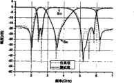
图2是本实用新型全波仿真S参数与测试S参数比较曲线图。Fig. 2 is a graph comparing the S-parameters of the full-wave simulation of the utility model with the S-parameters of the test.
具体实施方式Detailed ways
请参阅图1,所示为本实用新型的基于双分支线加载阶梯阻抗谐振器的双频带通滤波器10的结构示意图。Please refer to FIG. 1 , which is a schematic structural diagram of a dual-
在本实施例中,双频带带通滤波器10设置于基板20上,双频带带通滤波器10包括第一输入输出端1、第二输入输出端2,第一开环阶梯阻抗谐振器3、第二开环阶梯阻抗谐振器4,第一加载双分支线5、第二加载双分支线6,第一平行耦合微带线7、第二平行耦合微带线8。其中,第一开环阶梯阻抗谐振器3、第二开环阶梯阻抗谐振器4并排对称设置,其开环的开口相向设置,在第一开环阶梯阻抗谐振器3内开口的对面设有第一加载双分支线5,在第二开环阶梯阻抗谐振器4内开口的对面设有第二加载双分支线6;第一输入输出端1与第一开环阶梯阻抗谐振器3相连接,第二输入输出端2与第二开环阶梯阻抗谐振器4相连接;在第一开环阶梯阻抗谐振器3、第二开环阶梯阻抗谐振器4的上下两侧分别设有第一平行耦合微带线7、第二平行耦合微带线8。In this embodiment, the dual-
第一输入输出端1用于馈入电磁波信号,第二输入输出端2用于馈出电磁波信号,第一输入输出端1、第二输入输出端2平行设置,且为双频带带通滤波器10的50欧姆匹配阻抗,由于输入与输出信号在谐振器的基频时同相,故可称为0°馈电。第一开环阶梯阻抗谐振器3、第二开环阶梯阻抗谐振器4内部采用第二缝隙g2来内耦合,缝隙间可等效为一个电容。然后两开环阶梯阻抗谐振器间采用第一缝隙g1来级间耦合。第一开环阶梯阻抗谐振器3、第二开环阶梯阻抗谐振器4在连接第一输入输出端1、第二输入输出端2一侧部分的线宽,窄于其余各边的线宽,其余都等宽。通过第一开环阶梯阻抗谐振器3、第二开环阶梯阻抗谐振器4谐振到基频2.4GHz。第一加载双分支线5、第二加载双分支线6为各开环阶梯阻抗谐振器的左右两侧的对应中间部分,左右对称。通过改变其尺寸和相对位置可以对第二频带的带宽、中频、平坦度进行一定的调节。两个平行的第一平行耦合微带线7、第二平行耦合微带线8置于开环阶梯阻抗谐振器的上下两端,与开环阶梯阻抗谐振器相距第三缝隙g3,增加级间耦合,展宽第二频带的带宽。The first input and output terminal 1 is used to feed in the electromagnetic wave signal, and the second input and
请参阅图2,所示为通过HFSS软件全波仿真得到的数据图(虚线部分)和通过安捷伦网络分析仪实测得到的数据图(实线部分)的比较。我们可以看到实测曲线与仿真曲线的吻合程度比较理想。Please refer to Figure 2, which shows the comparison of the data graph (dotted line part) obtained through the full-wave simulation of HFSS software and the data graph (solid line part) obtained through the actual measurement of the Agilent network analyzer. We can see that the measured curve matches the simulated curve quite well.
图中横轴表示本发明基于双分支线加载阶梯阻抗谐振器的双频带通滤波器10的信号的频率(单位:GHz),纵轴表示幅度(单位:dB),包括透射的散射参数又称插入损耗(S21)的幅度以及反射的散射参数(S11)的幅度。Among the figure, the horizontal axis represents the frequency (unit: GHz) of the signal of the dual-
从图中我们可以看到本发明的基于双分支线加载阶梯阻抗谐振器的双频带通滤波器10具有良好的双频段特性。从曲线|S21|可以观察到在各通带内的插入损耗比较小,基本在1dB左右。虽然在两通带之间只有一个传输零点,但由于其零点在-40dB以下,两通带之间形成了一个比较满意的过渡坡。同时从曲线|S11|可观察到,在通频带内信号的反射系数绝对值大于14dB,在第一频段内其绝对值甚至达到了16dB以上。From the figure, we can see that the dual-
本实用新型的基于双分支线加载阶梯阻抗谐振器的双频带通滤波器10不需外加任何电容、电感等组件,可以通过调节滤波器的谐振单元的长度,加载双分支线和平行耦合微带线的尺寸和位置来达到所需的频段范围。由于本发明馈入与馈出信号线均为50欧姆传输线,所以此滤波器和其它外部组件相连时不需要串接额外的阻抗转换器,实则为进一步缩小了体积。The dual-
Claims (5)
Translated fromChinesePriority Applications (1)
| Application Number | Priority Date | Filing Date | Title |
|---|---|---|---|
| CN2010202913609UCN201804985U (en) | 2010-08-11 | 2010-08-11 | Dual-band bandpass filter based on double-branch loaded stepped impedance resonators |
Applications Claiming Priority (1)
| Application Number | Priority Date | Filing Date | Title |
|---|---|---|---|
| CN2010202913609UCN201804985U (en) | 2010-08-11 | 2010-08-11 | Dual-band bandpass filter based on double-branch loaded stepped impedance resonators |
Publications (1)
| Publication Number | Publication Date |
|---|---|
| CN201804985Utrue CN201804985U (en) | 2011-04-20 |
Family
ID=43874487
Family Applications (1)
| Application Number | Title | Priority Date | Filing Date |
|---|---|---|---|
| CN2010202913609UExpired - LifetimeCN201804985U (en) | 2010-08-11 | 2010-08-11 | Dual-band bandpass filter based on double-branch loaded stepped impedance resonators |
Country Status (1)
| Country | Link |
|---|---|
| CN (1) | CN201804985U (en) |
Cited By (3)
| Publication number | Priority date | Publication date | Assignee | Title |
|---|---|---|---|---|
| CN101916893A (en)* | 2010-08-11 | 2010-12-15 | 东南大学 | Dual-band bandpass filter based on double-branch loaded stepped impedance resonators |
| CN103515680A (en)* | 2012-06-18 | 2014-01-15 | 中国科学院深圳先进技术研究院 | Dual-mode band-pass filter and multi-order band-pass filter formed by the same |
| CN114497937A (en)* | 2022-01-04 | 2022-05-13 | 中信科移动通信技术股份有限公司 | Double-frequency microstrip filter |
- 2010
- 2010-08-11CNCN2010202913609Upatent/CN201804985U/ennot_activeExpired - Lifetime
Cited By (6)
| Publication number | Priority date | Publication date | Assignee | Title |
|---|---|---|---|---|
| CN101916893A (en)* | 2010-08-11 | 2010-12-15 | 东南大学 | Dual-band bandpass filter based on double-branch loaded stepped impedance resonators |
| CN101916893B (en)* | 2010-08-11 | 2013-01-09 | 东南大学 | Double frequency band-pass filter based on double branch line loading stepped -impedance resonator |
| CN103515680A (en)* | 2012-06-18 | 2014-01-15 | 中国科学院深圳先进技术研究院 | Dual-mode band-pass filter and multi-order band-pass filter formed by the same |
| CN103515680B (en)* | 2012-06-18 | 2017-02-01 | 中国科学院深圳先进技术研究院 | Dual-mode band-pass filter and multi-order band-pass filter formed by the same |
| CN114497937A (en)* | 2022-01-04 | 2022-05-13 | 中信科移动通信技术股份有限公司 | Double-frequency microstrip filter |
| CN114497937B (en)* | 2022-01-04 | 2023-08-18 | 中信科移动通信技术股份有限公司 | Dual-frequency microstrip filter |
Similar Documents
| Publication | Publication Date | Title |
|---|---|---|
| CN110034361A (en) | It is a kind of towards 5G communication miniature ultra wide band filtering function divide feeding network and its design method | |
| CN110165347B (en) | A High Isolation Microstrip Duplexer Loaded with Open Branches | |
| CN105990629A (en) | Broadband three-mode Balun band-pass filter based on E multi-mode resonators | |
| CN113140882A (en) | Miniaturized filtering crossing directional coupler with wide pass band and wide stop band response | |
| CN112072242A (en) | Filter structure and filter | |
| CN102610880A (en) | Plane miniaturization communication band-pass filter with broadband external inhibition characteristic | |
| CN201820868U (en) | Ultra-Wideband Filter Based on Ladder Impedance Resonator Loading | |
| CN106450610A (en) | A novel dual-passband filter | |
| CN201804985U (en) | Dual-band bandpass filter based on double-branch loaded stepped impedance resonators | |
| CN113471648B (en) | Four-mode branch knot loading resonator and dual-passband band-pass filter based on same | |
| CN113381143B (en) | A kind of microstrip low-pass filter and transmission zero point determination, frequency setting method | |
| CN101916893B (en) | Double frequency band-pass filter based on double branch line loading stepped -impedance resonator | |
| CN114976540A (en) | No-reflection band-pass filter based on three-wire coupling structure | |
| CN101764276A (en) | Quarter-wave resonant cavity band-pass filter of micro-strip coplanar waveguide composite structure | |
| CN105322252A (en) | U-shaped slot resonator-based ultra-wideband notch filter | |
| CN107634293A (en) | A Miniaturized Microstrip Low-Pass Filter with Two Transmission Zeros | |
| CN114464974B (en) | Circulator with filtering characteristic | |
| CN107681234B (en) | A three-pass microstrip filter with E-type resonators and stepped impedance resonators | |
| Chemseddine et al. | A design of compact microwave diplexer in microstrip technology based on band-stop filters using stepped impedance resonator | |
| CN103151582A (en) | Micro wave and micro band band-pass filter for miniature large double-frequency ratio wide band | |
| CN211578932U (en) | T-type loaded dual-passband microstrip filter | |
| CN110148820B (en) | Small coaxial cavity three-mode broadband filter based on step impedance cake loading | |
| CN113922020A (en) | Broadband high-rejection dual-passband filter composed of C-type resonators | |
| CN118231989B (en) | Miniaturized annular coupler with harmonic suppression and phase compensation | |
| CN106711556B (en) | Miniaturized microstrip quadruplex ware |
Legal Events
| Date | Code | Title | Description |
|---|---|---|---|
| C14 | Grant of patent or utility model | ||
| GR01 | Patent grant | ||
| AV01 | Patent right actively abandoned | Granted publication date:20110420 Effective date of abandoning:20130306 | |
| RGAV | Abandon patent right to avoid regrant |