CN201771875U - No-blade fan - Google Patents
No-blade fanDownload PDFInfo
- Publication number
- CN201771875U CN201771875UCN201020519265XUCN201020519265UCN201771875UCN 201771875 UCN201771875 UCN 201771875UCN 201020519265X UCN201020519265X UCN 201020519265XUCN 201020519265 UCN201020519265 UCN 201020519265UCN 201771875 UCN201771875 UCN 201771875U
- Authority
- CN
- China
- Prior art keywords
- air
- flow
- nozzle
- bladed fan
- mouth
- Prior art date
- Legal status (The legal status is an assumption and is not a legal conclusion. Google has not performed a legal analysis and makes no representation as to the accuracy of the status listed.)
- Expired - Fee Related
Links
Images


Classifications
- F—MECHANICAL ENGINEERING; LIGHTING; HEATING; WEAPONS; BLASTING
- F04—POSITIVE - DISPLACEMENT MACHINES FOR LIQUIDS; PUMPS FOR LIQUIDS OR ELASTIC FLUIDS
- F04D—NON-POSITIVE-DISPLACEMENT PUMPS
- F04D25/00—Pumping installations or systems
- F04D25/02—Units comprising pumps and their driving means
- F04D25/08—Units comprising pumps and their driving means the working fluid being air, e.g. for ventilation
- F—MECHANICAL ENGINEERING; LIGHTING; HEATING; WEAPONS; BLASTING
- F04—POSITIVE - DISPLACEMENT MACHINES FOR LIQUIDS; PUMPS FOR LIQUIDS OR ELASTIC FLUIDS
- F04F—PUMPING OF FLUID BY DIRECT CONTACT OF ANOTHER FLUID OR BY USING INERTIA OF FLUID TO BE PUMPED; SIPHONS
- F04F5/00—Jet pumps, i.e. devices in which flow is induced by pressure drop caused by velocity of another fluid flow
- F04F5/14—Jet pumps, i.e. devices in which flow is induced by pressure drop caused by velocity of another fluid flow the inducing fluid being elastic fluid
- F04F5/16—Jet pumps, i.e. devices in which flow is induced by pressure drop caused by velocity of another fluid flow the inducing fluid being elastic fluid displacing elastic fluids
- F—MECHANICAL ENGINEERING; LIGHTING; HEATING; WEAPONS; BLASTING
- F04—POSITIVE - DISPLACEMENT MACHINES FOR LIQUIDS; PUMPS FOR LIQUIDS OR ELASTIC FLUIDS
- F04F—PUMPING OF FLUID BY DIRECT CONTACT OF ANOTHER FLUID OR BY USING INERTIA OF FLUID TO BE PUMPED; SIPHONS
- F04F5/00—Jet pumps, i.e. devices in which flow is induced by pressure drop caused by velocity of another fluid flow
- F04F5/44—Component parts, details, or accessories not provided for in, or of interest apart from, groups F04F5/02 - F04F5/42
- F04F5/46—Arrangements of nozzles
Landscapes
- Engineering & Computer Science (AREA)
- Mechanical Engineering (AREA)
- General Engineering & Computer Science (AREA)
- Physics & Mathematics (AREA)
- Fluid Mechanics (AREA)
- Structures Of Non-Positive Displacement Pumps (AREA)
Abstract
Description
Technical field
The utility model relates to fan component, relates in particular to a kind of on-bladed fan that is used for producing in indoor environment air-flow and increase circulation of air flow.
Background technique
The conventional domestic fan generally includes a rotatingshaft, drives this blade or wheel rotation to produce the driving arrangement of air-flow around a cover blade or an impeller and being used to of this rotation.Flowing and circulation formation wind of air-flow, heat energy can obtain distributing consequently by cross-ventilation, and the user can experience nice and cool.The shortcoming of this conventional domestic fan is can not be experienced uniformly by the user by the blade of rotation or the air-flow of impeller generation, thereby the user can produce by the sensation of " beating " because of experiencing disorderly air-flow; Simultaneously, the blade occupation area is bigger, can reduce ambient brightness.
Existing a kind of on-bladed fan, it comprises the ring nozzle that the base portion that is used to form air-flow and support are located at this base portion, ring nozzle limits an opening, and nozzle comprises the mouth of inner passage and ejection air-flow, base portion comprises air inlet and the impeller of being located at its shell, and the discharge portion of impeller and the inner passage of nozzle are communicated with pipeline in the base portion respectively.Impeller passes through the air inlet extracting gases, the pipeline in the base portion of flowing through and the inner passage of nozzle, and the mouth by nozzle sprays air-flow (main air-flow) again; Entrainment its ambient air from the air-flow (main air-flow) of the mouth of nozzle ejection and entrainment air-flow (secondary airflow), entrainment air-flow mainly through opening that nozzle limited with formation.The air-flow that mouth sprayed of nozzle combines and forms the total air flow of launching forward from the opening that nozzle limited with entrainmenting air-flow, and this total air flow has approximate average velocity distributions in the diameter range of nozzle.Compare with the conventional domestic fan, existing on-bladed fan has lower turbulent flow to the air-flow that the user carries, and the user can experience uniform airflow more.
But existing on-bladed fan is owing to its reasons in structure has following shortcoming, and it mainly comprises:
One, existing on-bladed fan is that mouth ejection air-flow by nozzle entrainments its surrounding atmosphere and formed and entrainment air-flow, the air-flow that mouth sprayed of nozzle with entrainment the air-flow total air flow that formation launches forward from the opening that nozzle limited that combines.The mouth of nozzle is set to a finedraw usually, yet, only have only the airspeed that finedraw produced higher, the speed of entrainmenting air-flow is lower, thereby causes total air flow soft inadequately, even.
Two, the ring nozzle and the base portion of existing no leaf electric fan interfix, and the luffing mechanism of ring nozzle is arranged at outside the base portion.If change the last lower angle of air-flow that ring nozzle sprays, then need to make base portion to follow the ring nozzle unitary rotation, as ring nozzle is turned forward, base portion then forms an irregular body, take up room more, interfere with other article that are positioned over around the fan, and the pivoting angle of ring nozzle is big inadequately.
Three, well-known, there is a large amount of suspended dust particles in the air, dust have household electric appliance killer's title, and their existence greatly influences the performance of household electric appliance.The particulate matter that suspends in the air is made up of solid or liquid particle.Airborne particulates comprises the polydisperse aerosol of solid particle and liquid particulate.The air inlet of existing on-bladed fan is not provided with air filter; after using for a long time; airborne dust can stick to the mouth of pipeline, inner passage and nozzle in impeller, the base portion; especially its internal structure complexity due to the blade wheel structure; be difficult to take apart cleaning; if no air filter will adhere to too much dust, the motor load of impeller is increased, shorten its working life.Simultaneously, too much dust can cause the finedraw of nozzle mouth blocked, makes nozzle can not spray air-flow, thereby has shortened the working life of fan.
In summary, existing, on reality is used, obviously there are inconvenience and defective, so be necessary to be improved.
The model utility content
At above-mentioned defective, the purpose of this utility model is to provide a kind of on-bladed fan, and it can produce more even soft air-flow from the output face of fan.
To achieve these goals, the utility model provides a kind of on-bladed fan, comprise and be used to the nozzle that produces the pedestal of air-flow and be used to spray air-flow, described nozzle extends to limit an opening around an axis, and described nozzle comprises the collector ring and the mouth of launching air-flow that is used to receive from the air-flow of described pedestal, described mouth comprises two walls that are used to limit described mouth, described two walls are separated by at least one spacer member of extending along described mouth, described spacer member is connected with two walls of described mouth by fixed block, to form the multirow relief opening (fence type design) that extends along described mouth.
According to on-bladed fan of the present utility model, two adjacent row relief openings be arranged in parallel or shift to install.
According to on-bladed fan of the present utility model, described relief opening comprises the apparent surface who limits described relief opening, and the apparent surface of described multirow relief opening is 0.2mm~11mm apart from sum; The angle that forms between described relief opening and the described axis is 0.2 degree~7 degree; The length of described relief opening is 0.2mm~20mm.
According to on-bladed fan of the present utility model, described pedestal is provided with the support of the hollow that removably connects with described pedestal, described support is provided with the pitching pivot with through hole, and described nozzle is arranged at described support by described pitching pivot is rotatable.
According to on-bladed fan of the present utility model, be provided with electric machine casing in the described pedestal, the impeller that is installed with motor in the described electric machine casing and is connected with described electric machine rotational axis, have the exhaust passage in the described electric machine casing, and the through hole of described exhaust passage by described support and described pitching pivot is communicated with described collector ring.
According to on-bladed fan of the present utility model, the housing of described impeller and described pedestal is provided with gas-entered passageway, and described gas-entered passageway is provided with air filter.
According to on-bladed fan of the present utility model, described air filter is dismountable to be arranged at described gas-entered passageway.
According to on-bladed fan of the present utility model, the mouth of described nozzle is provided with a plurality of circular holes that are used to discharge air-flow, and the diameter of described circular hole is 0.2mm~10mm.
According to on-bladed fan of the present utility model, the width of described pedestal is no more than 2~3 times of width of described collector ring.
According to on-bladed fan of the present utility model, described base bottom also is provided with the support seat that is used for damping and supports described pedestal, and the height of described support seat is 5mm~35mm.
The utility model is separated two walls of described mouth by at least one spacer member of extending along the nozzle mouth, and described spacer member is connected with two walls of described mouth by fixed block, to form the multirow relief opening that extends along described mouth.During the operation of on-bladed fan, the multirow relief opening sprays air-flow simultaneously, has increased the area from air-flow that described mouth sprays, thereby the air-flow that makes the on-bladed fan be produced is more evenly soft.
Preferably, nozzle is by the rotatable support that is arranged at of pitching pivot, and nozzle can be that rotating shaft rotates freely in 360 degree scopes by the pitching pivot, thereby makes that the on-bladed fan can be in arbitrary orientation and arbitrary position to user's output gas flow.
The width of pedestal is no more than 2~3 times of width of collector ring, makes the form structure of on-bladed fan more compact, takies littler space.
Description of drawings
Fig. 1 is the front view of the utility model on-bladed fan;
Fig. 2 is the three-dimensional structure diagram of the nozzle of the utility model on-bladed fan;
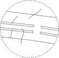
Fig. 3 is a kind of partial enlarged drawing of mode of execution of the nozzle of the utility model on-bladed fan;
Fig. 4 is the partial enlarged drawing of relief opening, spacer member and fixed block among Fig. 3;
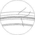
Fig. 5 is the partial enlarged drawing of another mode of execution of the nozzle of the utility model on-bladed fan;
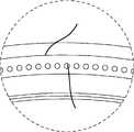
Fig. 6 is the partial enlarged drawing of another mode of execution of the nozzle of the utility model on-bladed fan;
Fig. 7 is the side cross-sectional view of the utility model on-bladed fan along A-A line intercepting among Fig. 1;
Fig. 8 is the lateral section partial enlarged drawing of the utility model on-bladed fan;
Fig. 9 is the partial enlarged drawing of nozzle among Fig. 8;
Figure 10 is the side surface chart of the utility model on-bladed fan along B-B line intercepting among Fig. 7.
Figure 11 is the partial enlarged drawing of pitching pivot of the present utility model.
Embodiment
In order to make the purpose of this utility model, technological scheme and advantage clearer,, the utility model is further elaborated below in conjunction with drawings and Examples.Should be appreciated that specific embodiment described herein only in order to explanation the utility model, and be not used in qualification the utility model.
As Fig. 1~shown in Figure 11, a kind of on-bladed fan 100 of the utility model, comprise and be used to thering nozzle 20 that produces thepedestal 10 of air-flow and be used to spray air-flow,nozzle 20 extends to limit an opening 30 around an axis X, andnozzle 20 comprises the collector ring 21 and the mouth 22 of launching air-flow that is used to receive from the air-flow of pedestal 10.As Fig. 4 and shown in Figure 9, mouth 22 comprises two walls 221,222 that are used to limit mouth 22, two walls 221,222 are separated by at least onespacer member 23 of extending along mouth 22,spacer member 23 roughly circularizes,spacer member 23 is connected with two walls 221,222 of mouth 22 by fixed block, thereby forms the multirow relief opening 25 (fence type design) that extends along mouth 22.Two walls 221,222 of fixed block,spacer member 23 and mouth 22 are one-body molded.In the embodiment of Fig. 3~shown in Figure 5,relief opening 25 is arranged in two row, and obviouslyrelief opening 25 also can be set to triplex row or multirow.
Preferably, as Fig. 3 and shown in Figure 5, two adjacentrow relief openings 25 be arranged in parallel or shift to install, and in Fig. 3, becauserelief opening 25 has certain radian, two adjacentrow relief openings 25 are parallel camber line.Adopt orderly arranging method, improved airflow state, can make from the air-flow of mouth 22 ejection in order, steadily, not disorderly.
When 100 operations of on-bladed fan, the gas thatpedestal 10 is produced is through mouth 22 ejections ofnozzle 20, to produce the air-flow that the opening 30 that limited fromnozzle 20 is launched forward, entrainment its ambient air from the air-flow (main air-flow) of mouth 22 ejection and entrainment air-flow (secondary airflow), entrainment the opening 30 that air-flow is mainly limited throughnozzle 20 with formation.The air-flow that mouth 22 is sprayed combines and forms the total air flow that the opening 30 that limited fromnozzle 20 is launched forward with entrainmenting air-flow, and this total air flow has approximate average velocity distributions in the diameter range of nozzle 20.Simultaneously, multirow relief opening 25 sprays air-flow simultaneously, and the air-flow that makes mouth 22 be sprayed roughly becomes ring, and the flow area of its generation is big, and air-flow is more evenly soft.Whereby, the utility model increased from mouth 22 spray the area of air-flow, thereby the air-flow that makes on-bladedfan 100 be produced is more evenly soft.
Collector ring 21 comprises gradually narrow conical region, andmultirow relief opening 25 is positioned at the end of conical region, and relief opening 25 to small part is an annular.As shown in Figure 9,relief opening 25 comprises the apparent surface 251,252 who limits it, and the apparent surface ofmultirow relief opening 25 is preferably 0.2mm~11mm apart from sum; The angle that forms betweenrelief opening 25 and the axis X is preferably 0.2 degree~7 degree; The length ofrelief opening 25 is preferably 0.2mm~20mm.And the air-flow thatmultirow relief opening 25 is sprayed converges through being directed on the X-axis line, make air-flow thatnozzle 20 produced roughly to circularize or circle sprays forward, air-flow is more concentrated, loss energy and airspeed still less, even the user is far away from on-bladed fan 100, still can experience nice and cool effect.
Preferably,relief opening 25 also can be set to the circular hole formula, and as shown in Figure 6, the mouth 22 ofnozzle 20 is provided with a plurality of circular holes 26 that are used to discharge air-flow, and a plurality of circular hole 26 extends along mouth 22, and the diameter of circular hole 26 is 0.2mm~10mm.Adopt this mode can roughly become the air-flow of ring equally, can realize that on-bladed fan 100 produces the effect of evenly soft air-flow fromnozzle 20 ejections.
As shown in figure 10,pedestal 10 inside are provided withelectric machine casing 11, and theimpeller 13 that is installed withmotor 12 in theelectric machine casing 11 and is connected withmotor 12 running shafts,motor 12 are preferably dc brushless motor or mixed flow motor.Pedestal 10 is provided with andpedestal 10support 14 that removably connects, andsupport 14 has ahollow channel 141, and the profile ofsupport 14 is roughly and the adaptive semicircle ofnozzle 20 lower half portions.The two ends ofsupport 14 are respectively equipped with thepitching pivot 15 with through hole 151, andnozzle 20 is by thepitching pivot 15rotatable supports 14 that are arranged at.In the present embodiment,nozzle 20 can be rotated freely in 360 degree scopes for rotating shaft bypitching pivot 15, thereby make that on-bladed fan 100 can be in arbitrary orientation and arbitrary position to user's output gas flow, it can be positioned on the floor, on the desktop and on the vertical body of wall, the luffing angle that only need adjust installation position andnozzle 20 gets final product.Simultaneously, support 14 removably connects withpedestal 10, when on-bladedfan 100 leaves unused, support 14 andpedestal 10 can be taken apart, more saves the space.
The housing ofpedestal 10 is provided with a plurality ofselector buttons 17 and suction port, and this suction port comprises primary air inlet that is positioned atpedestal 10 bottoms and/or the extra-air inlet that is positioned atpedestal 10sidewalls.Impeller 13 is provided with gas-entered passageway with the housing ofpedestal 10, and this gas-entered passageway is provided with air filter 19.This gas-entered passageway comprises the induction part of suction port,impeller 13 and the air-flow path between suction port andimpeller 13 induction part.In the embodiment shown in fig. 10, only illustrated thatair filter 19 is arranged at the situation of the induction part ofimpeller 13, can associate thatair filter 19 also can be arranged at the air-flow path between suction port and suction port andimpeller 13 induction part.Electric machine casing 11 inside haveexhaust passage 16, andexhaust passage 16 is communicated with collector ring 21 by thehollow channel 141 ofsupport 14 and the through hole 151 of pitching pivot 15.Thereby, gas-entered passageway,exhaust passage 16,hollow channel 141, through hole 151, collector ring 21 and a plurality ofrelief opening 25 form the air-flow path that connects continuously, duringmotor 12 runnings, gas entersfan 100 inside through the extraction ofimpeller 13 from the external world, through a plurality of relief opening 25 ejections.
Preferably,air filter 19 dismountable this gas-entered passageways that are arranged at are convenient to clean.Thisair filter 19 is set to airstrainer usually, can keep airborne dust can not enter on-bladedfan 100 inside, avoid dust to adhere to impeller 13,exhaust passage 16, collector ring 21 andrelief opening 25, kept the unimpeded of on-bladedfan 100 internal gas flow passages, keep the cleaning of on-bladed fan 100 inside, thereby make on-bladed fan 100 have longer working life.Obviously, other are used for filtered air and play reducing dust and entering the filtrating equipment of effect of on-bladedfan 100 inside still within protection domain of the present utility model.
According to an embodiment of the present utility model, when the user selects to start on-bladedfan 100 from a plurality ofselector buttons 17,motor 12 rotates and drivesimpeller 13, gas enterspedestal 10 from the external world, afterprocess air filter 19 filters, enter the induction part ofimpeller 13, the air pressure of gas increased and formed high velocity air this moment, this high velocityair exhaust passage 16 of flowing through again, and be divided in opposite direction two strands of air-flows bysupport 14, these two strands of air-flows enter collector ring 21 through the through hole 151 ofpitching pivot 15,21 pairs of these high velocity airs of collector ring carry out rectification, high velocity air after the rectification is restricted when entering conical region and a plurality ofrelief opening 25, sprays outside the on-bladed fans 100 to form main air-flow through a plurality of relief openings 25.This main air-flow entrainments its ambient air and entrainments air-flow (secondary airflow) with formation when a plurality ofrelief openings 25 spray, entrainment the opening 30 that air-flow is mainly limited throughnozzle 20, the main air-flow that a plurality ofrelief openings 25 are sprayed combines and forms the total air flow that the opening 30 that limited fromnozzle 20 is launched forward with entrainmenting air-flow, and this total air flow has approximate average velocity distributions in the diameter range of nozzle 20.Thereby the user experiences uniform airflow, reaches refrigeration.
As shown in Figure 7, the width ofpedestal 10 is not more than 2~3 times of width of collector ring 21.The size ofpedestal 10 is little with respect to the size ofnozzle 20, make the profile of whole on-bladed fan 100 more compact, has reduced the shared space of on-bladed fan 100, has more aesthetic simultaneously.
Preferably, be provided withpedestal 10 housings on primary air inlet be arranged on the same axis with the induction part ofimpeller 13 is corresponding, and the diameter of primary air inlet is big than the diameter of the induction part of impeller 13.When impeller 13 extracting gases, extraneous gas enters primary air inlet with arc mode and relatively low speed all around throughpedestal 10 bottoms, formation air-flow buffering can not make the direction generation cataclysm of air-flow, thereby produces big noise when avoiding 100 work of on-bladed fan.
Preferably,pedestal 10 bottoms also are provided with thesupport seat 40 that is used for damping and supportingbase 10, and the height ofsupport seat 40 is 5mm~35mm, make that air inlet was more smooth and easy to obtain bigger air-flow when on-bladedfan 100 was positioned over desktop.
In sum, the utility model is separated two walls of described mouth by at least one spacer member of extending along the nozzle mouth, described spacer member is connected with two walls of described mouth by fixed block, to form the multirow relief opening that extends along described mouth, during the operation of on-bladed fan, the multirow relief opening sprays air-flow simultaneously, has increased the area from air-flow that described mouth sprays, thereby the air-flow that makes the on-bladed fan be produced is more evenly soft.Preferably, nozzle is by the rotatable support that is arranged at of pitching pivot, and nozzle can be that rotating shaft rotates freely in 360 degree scopes by the pitching pivot, thereby makes that the on-bladed fan can be in arbitrary orientation and arbitrary position to user's output gas flow.
Certainly; the utility model also can have other various embodiments; under the situation that does not deviate from the utility model spirit and essence thereof; those of ordinary skill in the art work as can make various corresponding changes and distortion according to the utility model, but these corresponding changes and distortion all should belong to the protection domain of the appended claim of the utility model.
Claims (10)
1. on-bladed fan, comprise and be used to the nozzle that produces the pedestal of air-flow and be used to spray air-flow, described nozzle extends to limit an opening around an axis, and described nozzle comprises the collector ring and the mouth of launching air-flow that is used to receive from the air-flow of described pedestal, it is characterized in that, described mouth comprises two walls that are used to limit described mouth, described two walls are separated by at least one spacer member of extending along described mouth, described spacer member is connected with two walls of described mouth by fixed block, to form the multirow relief opening that extends along described mouth.
2. on-bladed fan according to claim 1 is characterized in that, two adjacent row relief openings be arranged in parallel or shift to install.
3. on-bladed fan according to claim 1 is characterized in that described relief opening comprises the apparent surface who limits described relief opening, and the apparent surface of described multirow relief opening is 0.2mm~11mm apart from sum; The angle that forms between described relief opening and the described axis is 0.2 degree~7 degree; The length of described relief opening is 0.2mm~20mm.
4. on-bladed fan according to claim 1, it is characterized in that, described pedestal is provided with the support of the hollow that removably connects with described pedestal, and described support is provided with the pitching pivot with through hole, and described nozzle is arranged at described support by described pitching pivot is rotatable.
5. on-bladed fan according to claim 4, it is characterized in that, be provided with electric machine casing in the described pedestal, the impeller that is installed with motor in the described electric machine casing and is connected with described electric machine rotational axis, have the exhaust passage in the described electric machine casing, and the through hole of described exhaust passage by described support and described pitching pivot is communicated with described collector ring.
6. on-bladed fan according to claim 5 is characterized in that the housing of described impeller and described pedestal is provided with gas-entered passageway, and described gas-entered passageway is provided with air filter.
7. on-bladed fan according to claim 6 is characterized in that, described air filter is dismountable to be arranged at described gas-entered passageway.
8. on-bladed fan according to claim 1 is characterized in that, the mouth of described nozzle is provided with a plurality of circular holes that are used to discharge air-flow, and the diameter of described circular hole is 0.2mm~10mm.
9. on-bladed fan according to claim 1 is characterized in that, the width of described pedestal is no more than 2~3 times of width of described collector ring.
10. on-bladed fan according to claim 1 is characterized in that, described base bottom also is provided with the support seat that is used for damping and supports described pedestal, and the height of described support seat is 5mm~35mm.
Priority Applications (22)
| Application Number | Priority Date | Filing Date | Title |
|---|---|---|---|
| CN201020519265XUCN201771875U (en) | 2010-09-07 | 2010-09-07 | No-blade fan |
| PL15180299TPL2990663T3 (en) | 2010-05-27 | 2011-05-25 | Device for blowing air by means of narrow slit nozzle assembly |
| ES15180299.8TES2640716T3 (en) | 2010-05-27 | 2011-05-25 | Air blowing device by means of a narrow slot nozzle assembly |
| CA2800681ACA2800681C (en) | 2010-05-27 | 2011-05-25 | Device for blowing air by means of narrow slit nozzle assembly |
| EP15180299.8AEP2990663B1 (en) | 2010-05-27 | 2011-05-25 | Device for blowing air by means of narrow slit nozzle assembly |
| HUE15180299AHUE034461T2 (en) | 2010-05-27 | 2011-05-25 | Device for blowing air by means of narrow slit nozzle assembly |
| JP2013511526AJP5442166B2 (en) | 2010-05-27 | 2011-05-25 | Apparatus for blowing air through a slit nozzle assembly. |
| EP11786090.8AEP2578889B1 (en) | 2010-05-27 | 2011-05-25 | Device for blowing air by means of narrow slit nozzle assembly |
| DK11786090.8TDK2578889T3 (en) | 2010-05-27 | 2011-05-25 | Device for blasting air by narrow spalte nozzle device |
| PL11786090TPL2578889T3 (en) | 2010-05-27 | 2011-05-25 | Device for blowing air by means of narrow slit nozzle assembly |
| PCT/CN2011/074668WO2011147318A1 (en) | 2010-05-27 | 2011-05-25 | Device for blowing air by means of narrow slit nozzle assembly |
| HK13108512.7AHK1181444B (en) | 2010-05-27 | 2011-05-25 | Device for blowing air by means of a nozzle assembly |
| DK15180299.8TDK2990663T3 (en) | 2010-05-27 | 2011-05-25 | DEVICE FOR Blowing air by means of narrow slit nozzle |
| GB1220856.7AGB2493672B (en) | 2010-05-27 | 2011-05-25 | Device for blowing air by means of a nozzle assembly |
| SG2012086948ASG186071A1 (en) | 2010-05-27 | 2011-05-25 | Device for blowing air by means of narrow slit nozzle assembly |
| AU2011257733AAU2011257733B2 (en) | 2010-05-27 | 2011-05-25 | Device for blowing air by means of narrow slit nozzle assembly |
| ES11786090.8TES2553148T3 (en) | 2010-05-27 | 2011-05-25 | Air blowing device by means of a narrow slit nozzle assembly |
| KR1020127008041AKR101295170B1 (en) | 2010-05-27 | 2011-05-25 | Device for Blowing Air by Means of Narrow Slit Nozzle Assembly |
| MYPI2012700992MY152313A (en) | 2010-05-27 | 2011-05-25 | Device for blowing air by means of a nozzle assembly |
| HUE11786090AHUE026393T2 (en) | 2010-05-27 | 2011-05-25 | Device for blowing air by means of narrow slit nozzle assembly |
| US13/686,480US8721307B2 (en) | 2010-05-27 | 2012-11-27 | Device for blowing air by means of narrow slit nozzle assembly |
| US14/264,955US9011116B2 (en) | 2010-05-27 | 2014-04-29 | Device for blowing air by means of a nozzle assembly |
Applications Claiming Priority (1)
| Application Number | Priority Date | Filing Date | Title |
|---|---|---|---|
| CN201020519265XUCN201771875U (en) | 2010-09-07 | 2010-09-07 | No-blade fan |
Publications (1)
| Publication Number | Publication Date |
|---|---|
| CN201771875Utrue CN201771875U (en) | 2011-03-23 |
Family
ID=43751721
Family Applications (1)
| Application Number | Title | Priority Date | Filing Date |
|---|---|---|---|
| CN201020519265XUExpired - Fee RelatedCN201771875U (en) | 2010-05-27 | 2010-09-07 | No-blade fan |
Country Status (1)
| Country | Link |
|---|---|
| CN (1) | CN201771875U (en) |
Cited By (53)
| Publication number | Priority date | Publication date | Assignee | Title |
|---|---|---|---|---|
| WO2011147318A1 (en)* | 2010-05-27 | 2011-12-01 | Li Dezheng | Device for blowing air by means of narrow slit nozzle assembly |
| CN102338133A (en)* | 2011-09-30 | 2012-02-01 | 东莞市旭尔美电器科技有限公司 | A bladeless fan |
| CN102878121A (en)* | 2011-07-12 | 2013-01-16 | 任文华 | Bladeless fan |
| CN102996531A (en)* | 2012-12-11 | 2013-03-27 | 李耀强 | Bladeless fan with dual angle nozzle |
| CN103225631A (en)* | 2012-01-28 | 2013-07-31 | 任文华 | Bladeless fan and nozzle for bladeless fan |
| CN103306944A (en)* | 2012-03-06 | 2013-09-18 | 戴森技术有限公司 | Humidifying apparatus |
| CN103306949A (en)* | 2012-03-06 | 2013-09-18 | 戴森技术有限公司 | Humidifying apparatus |
| CN103375444A (en)* | 2012-04-11 | 2013-10-30 | 江西维特科技有限公司 | Bladeless fan and nozzle thereof |
| CN103375442A (en)* | 2012-04-11 | 2013-10-30 | 江西维特科技有限公司 | Bladeless fan and nozzle thereof |
| CN103398030A (en)* | 2013-08-14 | 2013-11-20 | 赛恩斯能源科技有限公司 | Multifunctional portable bladeless fan |
| US20140077398A1 (en)* | 2012-03-06 | 2014-03-20 | Dyson Technology Limited | Humidifying apparatus |
| US8967980B2 (en) | 2010-10-18 | 2015-03-03 | Dyson Technology Limited | Fan assembly |
| US8967979B2 (en) | 2010-10-18 | 2015-03-03 | Dyson Technology Limited | Fan assembly |
| US9004878B2 (en) | 2009-11-06 | 2015-04-14 | Dyson Technology Limited | Fan having a magnetically attached remote control |
| USD728092S1 (en) | 2013-08-01 | 2015-04-28 | Dyson Technology Limited | Fan |
| USD728769S1 (en) | 2013-08-01 | 2015-05-05 | Dyson Technology Limited | Fan |
| USD728770S1 (en) | 2013-08-01 | 2015-05-05 | Dyson Technology Limited | Fan |
| CN104595162A (en)* | 2015-01-20 | 2015-05-06 | 广东美的环境电器制造有限公司 | Pitching structure of bladeless fan and bladeless fan |
| USD729373S1 (en) | 2013-03-07 | 2015-05-12 | Dyson Technology Limited | Fan |
| USD729374S1 (en) | 2013-03-07 | 2015-05-12 | Dyson Technology Limited | Fan |
| USD729372S1 (en) | 2013-03-07 | 2015-05-12 | Dyson Technology Limited | Fan |
| USD729376S1 (en) | 2013-03-07 | 2015-05-12 | Dyson Technology Limited | Fan |
| USD729375S1 (en) | 2013-03-07 | 2015-05-12 | Dyson Technology Limited | Fan |
| USD729925S1 (en) | 2013-03-07 | 2015-05-19 | Dyson Technology Limited | Fan |
| US9127689B2 (en) | 2009-03-04 | 2015-09-08 | Dyson Technology Limited | Fan assembly |
| US9127855B2 (en) | 2011-07-27 | 2015-09-08 | Dyson Technology Limited | Fan assembly |
| US9151299B2 (en) | 2012-02-06 | 2015-10-06 | Dyson Technology Limited | Fan |
| USD746425S1 (en) | 2013-01-18 | 2015-12-29 | Dyson Technology Limited | Humidifier |
| USD746966S1 (en) | 2013-01-18 | 2016-01-05 | Dyson Technology Limited | Humidifier |
| USD747450S1 (en) | 2013-01-18 | 2016-01-12 | Dyson Technology Limited | Humidifier |
| US9249809B2 (en) | 2012-02-06 | 2016-02-02 | Dyson Technology Limited | Fan |
| USD749231S1 (en) | 2013-01-18 | 2016-02-09 | Dyson Technology Limited | Humidifier |
| US9283573B2 (en) | 2012-02-06 | 2016-03-15 | Dyson Technology Limited | Fan assembly |
| US9410711B2 (en) | 2013-09-26 | 2016-08-09 | Dyson Technology Limited | Fan assembly |
| US9458853B2 (en) | 2011-07-27 | 2016-10-04 | Dyson Technology Limited | Fan assembly |
| US9599356B2 (en) | 2014-07-29 | 2017-03-21 | Dyson Technology Limited | Humidifying apparatus |
| US9745981B2 (en) | 2011-11-11 | 2017-08-29 | Dyson Technology Limited | Fan assembly |
| US9752789B2 (en) | 2012-03-06 | 2017-09-05 | Dyson Technology Limited | Humidifying apparatus |
| US9797612B2 (en) | 2013-01-29 | 2017-10-24 | Dyson Technology Limited | Fan assembly |
| US9822778B2 (en) | 2012-04-19 | 2017-11-21 | Dyson Technology Limited | Fan assembly |
| US9903602B2 (en) | 2014-07-29 | 2018-02-27 | Dyson Technology Limited | Humidifying apparatus |
| US9926804B2 (en) | 2010-11-02 | 2018-03-27 | Dyson Technology Limited | Fan assembly |
| US9927136B2 (en) | 2012-03-06 | 2018-03-27 | Dyson Technology Limited | Fan assembly |
| US9982677B2 (en) | 2014-07-29 | 2018-05-29 | Dyson Technology Limited | Fan assembly |
| US10094392B2 (en) | 2011-11-24 | 2018-10-09 | Dyson Technology Limited | Fan assembly |
| US10100836B2 (en) | 2010-10-13 | 2018-10-16 | Dyson Technology Limited | Fan assembly |
| US10145583B2 (en) | 2012-04-04 | 2018-12-04 | Dyson Technology Limited | Heating apparatus |
| CN109185238A (en)* | 2018-11-19 | 2019-01-11 | 浙江工商大学 | A kind of noise abatement formula bladeless fan structure |
| US10344773B2 (en) | 2010-08-06 | 2019-07-09 | Dyson Technology Limited | Fan assembly |
| US10408478B2 (en) | 2012-03-06 | 2019-09-10 | Dyson Technology Limited | Humidifying apparatus |
| US10612565B2 (en) | 2013-01-29 | 2020-04-07 | Dyson Technology Limited | Fan assembly |
| US12102205B2 (en) | 2023-01-19 | 2024-10-01 | Sharkninja Operating Llc | Hair care appliance with powered attachment |
| US12220035B2 (en) | 2023-01-19 | 2025-02-11 | Sharkninja Operating Llc | Hair care appliance with powered attachment |
- 2010
- 2010-09-07CNCN201020519265XUpatent/CN201771875U/ennot_activeExpired - Fee Related
Cited By (69)
| Publication number | Priority date | Publication date | Assignee | Title |
|---|---|---|---|---|
| US9127689B2 (en) | 2009-03-04 | 2015-09-08 | Dyson Technology Limited | Fan assembly |
| US10221860B2 (en) | 2009-03-04 | 2019-03-05 | Dyson Technology Limited | Fan assembly |
| US9004878B2 (en) | 2009-11-06 | 2015-04-14 | Dyson Technology Limited | Fan having a magnetically attached remote control |
| WO2011147318A1 (en)* | 2010-05-27 | 2011-12-01 | Li Dezheng | Device for blowing air by means of narrow slit nozzle assembly |
| GB2493672A (en)* | 2010-05-27 | 2013-02-13 | Dyson Technology Ltd | Device for blowing air by means of narrow slit nozzle assembly |
| GB2493672B (en)* | 2010-05-27 | 2013-07-10 | Dyson Technology Ltd | Device for blowing air by means of a nozzle assembly |
| US9011116B2 (en) | 2010-05-27 | 2015-04-21 | Dyson Technology Limited | Device for blowing air by means of a nozzle assembly |
| US10344773B2 (en) | 2010-08-06 | 2019-07-09 | Dyson Technology Limited | Fan assembly |
| US10100836B2 (en) | 2010-10-13 | 2018-10-16 | Dyson Technology Limited | Fan assembly |
| US8967980B2 (en) | 2010-10-18 | 2015-03-03 | Dyson Technology Limited | Fan assembly |
| US8967979B2 (en) | 2010-10-18 | 2015-03-03 | Dyson Technology Limited | Fan assembly |
| US9926804B2 (en) | 2010-11-02 | 2018-03-27 | Dyson Technology Limited | Fan assembly |
| CN102878121A (en)* | 2011-07-12 | 2013-01-16 | 任文华 | Bladeless fan |
| US9127855B2 (en) | 2011-07-27 | 2015-09-08 | Dyson Technology Limited | Fan assembly |
| US9291361B2 (en) | 2011-07-27 | 2016-03-22 | Dyson Technology Limited | Fan assembly |
| US9335064B2 (en) | 2011-07-27 | 2016-05-10 | Dyson Technology Limited | Fan assembly |
| US9458853B2 (en) | 2011-07-27 | 2016-10-04 | Dyson Technology Limited | Fan assembly |
| US10094581B2 (en) | 2011-07-27 | 2018-10-09 | Dyson Technology Limited | Fan assembly |
| CN102338133A (en)* | 2011-09-30 | 2012-02-01 | 东莞市旭尔美电器科技有限公司 | A bladeless fan |
| US9745981B2 (en) | 2011-11-11 | 2017-08-29 | Dyson Technology Limited | Fan assembly |
| US10094392B2 (en) | 2011-11-24 | 2018-10-09 | Dyson Technology Limited | Fan assembly |
| CN103225631B (en)* | 2012-01-28 | 2015-12-02 | 任文华 | Bladeless fans and nozzles for bladeless fans |
| CN103225631A (en)* | 2012-01-28 | 2013-07-31 | 任文华 | Bladeless fan and nozzle for bladeless fan |
| US9283573B2 (en) | 2012-02-06 | 2016-03-15 | Dyson Technology Limited | Fan assembly |
| US9249809B2 (en) | 2012-02-06 | 2016-02-02 | Dyson Technology Limited | Fan |
| US9151299B2 (en) | 2012-02-06 | 2015-10-06 | Dyson Technology Limited | Fan |
| US10465928B2 (en) | 2012-03-06 | 2019-11-05 | Dyson Technology Limited | Humidifying apparatus |
| CN103306944A (en)* | 2012-03-06 | 2013-09-18 | 戴森技术有限公司 | Humidifying apparatus |
| CN103306944B (en)* | 2012-03-06 | 2016-09-14 | 戴森技术有限公司 | Damping device |
| US9366449B2 (en) | 2012-03-06 | 2016-06-14 | Dyson Technology Limited | Humidifying apparatus |
| US10563875B2 (en) | 2012-03-06 | 2020-02-18 | Dyson Technology Limited | Humidifying apparatus |
| US10408478B2 (en) | 2012-03-06 | 2019-09-10 | Dyson Technology Limited | Humidifying apparatus |
| CN103306949B (en)* | 2012-03-06 | 2016-04-27 | 戴森技术有限公司 | Damping device |
| US20140077398A1 (en)* | 2012-03-06 | 2014-03-20 | Dyson Technology Limited | Humidifying apparatus |
| US9797613B2 (en)* | 2012-03-06 | 2017-10-24 | Dyson Technology Limited | Humidifying apparatus |
| US9927136B2 (en) | 2012-03-06 | 2018-03-27 | Dyson Technology Limited | Fan assembly |
| US9752789B2 (en) | 2012-03-06 | 2017-09-05 | Dyson Technology Limited | Humidifying apparatus |
| CN103306949A (en)* | 2012-03-06 | 2013-09-18 | 戴森技术有限公司 | Humidifying apparatus |
| US10145583B2 (en) | 2012-04-04 | 2018-12-04 | Dyson Technology Limited | Heating apparatus |
| CN103375444A (en)* | 2012-04-11 | 2013-10-30 | 江西维特科技有限公司 | Bladeless fan and nozzle thereof |
| CN103375442A (en)* | 2012-04-11 | 2013-10-30 | 江西维特科技有限公司 | Bladeless fan and nozzle thereof |
| US9822778B2 (en) | 2012-04-19 | 2017-11-21 | Dyson Technology Limited | Fan assembly |
| CN102996531B (en)* | 2012-12-11 | 2015-12-02 | 长乐市丽智产品设计有限公司 | Bladeless fan with dual angle nozzle |
| CN102996531A (en)* | 2012-12-11 | 2013-03-27 | 李耀强 | Bladeless fan with dual angle nozzle |
| USD746966S1 (en) | 2013-01-18 | 2016-01-05 | Dyson Technology Limited | Humidifier |
| USD749231S1 (en) | 2013-01-18 | 2016-02-09 | Dyson Technology Limited | Humidifier |
| USD747450S1 (en) | 2013-01-18 | 2016-01-12 | Dyson Technology Limited | Humidifier |
| USD746425S1 (en) | 2013-01-18 | 2015-12-29 | Dyson Technology Limited | Humidifier |
| US10612565B2 (en) | 2013-01-29 | 2020-04-07 | Dyson Technology Limited | Fan assembly |
| US9797612B2 (en) | 2013-01-29 | 2017-10-24 | Dyson Technology Limited | Fan assembly |
| USD729372S1 (en) | 2013-03-07 | 2015-05-12 | Dyson Technology Limited | Fan |
| USD729373S1 (en) | 2013-03-07 | 2015-05-12 | Dyson Technology Limited | Fan |
| USD729925S1 (en) | 2013-03-07 | 2015-05-19 | Dyson Technology Limited | Fan |
| USD729375S1 (en) | 2013-03-07 | 2015-05-12 | Dyson Technology Limited | Fan |
| USD729374S1 (en) | 2013-03-07 | 2015-05-12 | Dyson Technology Limited | Fan |
| USD729376S1 (en) | 2013-03-07 | 2015-05-12 | Dyson Technology Limited | Fan |
| USD728769S1 (en) | 2013-08-01 | 2015-05-05 | Dyson Technology Limited | Fan |
| USD728770S1 (en) | 2013-08-01 | 2015-05-05 | Dyson Technology Limited | Fan |
| USD728092S1 (en) | 2013-08-01 | 2015-04-28 | Dyson Technology Limited | Fan |
| CN103398030A (en)* | 2013-08-14 | 2013-11-20 | 赛恩斯能源科技有限公司 | Multifunctional portable bladeless fan |
| US9410711B2 (en) | 2013-09-26 | 2016-08-09 | Dyson Technology Limited | Fan assembly |
| US9982677B2 (en) | 2014-07-29 | 2018-05-29 | Dyson Technology Limited | Fan assembly |
| US9903602B2 (en) | 2014-07-29 | 2018-02-27 | Dyson Technology Limited | Humidifying apparatus |
| US9599356B2 (en) | 2014-07-29 | 2017-03-21 | Dyson Technology Limited | Humidifying apparatus |
| CN104595162A (en)* | 2015-01-20 | 2015-05-06 | 广东美的环境电器制造有限公司 | Pitching structure of bladeless fan and bladeless fan |
| CN109185238A (en)* | 2018-11-19 | 2019-01-11 | 浙江工商大学 | A kind of noise abatement formula bladeless fan structure |
| CN109185238B (en)* | 2018-11-19 | 2019-08-23 | 浙江工商大学 | A kind of noise abatement formula bladeless fan structure |
| US12102205B2 (en) | 2023-01-19 | 2024-10-01 | Sharkninja Operating Llc | Hair care appliance with powered attachment |
| US12220035B2 (en) | 2023-01-19 | 2025-02-11 | Sharkninja Operating Llc | Hair care appliance with powered attachment |
Similar Documents
| Publication | Publication Date | Title |
|---|---|---|
| CN201771875U (en) | No-blade fan | |
| CN201874898U (en) | Fan without blades | |
| CN201739198U (en) | Bladeless electric fan | |
| CN201739199U (en) | Blade-less electric fin based on USB power supply | |
| CN202091268U (en) | Foldable bladeless fan | |
| CN107327941B (en) | Indoor unit of vertical air conditioner and air conditioner | |
| US12050020B2 (en) | Air filter device | |
| WO2020171718A1 (en) | Air filter device | |
| CN205478414U (en) | Humidification dust removal bladeless fan | |
| AU2020226138A1 (en) | Air filter device | |
| CN103939371A (en) | Bladeless fan | |
| CN206414220U (en) | Dust catcher exhaust air flue | |
| CN102817859A (en) | Electric fan with double wind-collecting wind wheels and blade-free air-blowing head | |
| CN202109560U (en) | Range hood | |
| CN207230683U (en) | A kind of range hood | |
| CN106704226A (en) | Fan | |
| CN207214200U (en) | A kind of range hood | |
| CN201074601Y (en) | Jet-flow type blower structure with air entering from back | |
| CN202144777U (en) | Refrigeration bladeless fan | |
| CN201470245U (en) | Line spray pulse long bag filter | |
| CN212408770U (en) | Rotary smoking machine | |
| CN213020145U (en) | Air purifier | |
| CN203809326U (en) | Bladeless fan | |
| CN111981527B (en) | Range hood with central air curtain and side air curtain | |
| CN201977707U (en) | Collecting device and dust collector comprising same |
Legal Events
| Date | Code | Title | Description |
|---|---|---|---|
| C14 | Grant of patent or utility model | ||
| GR01 | Patent grant | ||
| ASS | Succession or assignment of patent right | Owner name:YING HUI Effective date:20121011 | |
| C41 | Transfer of patent application or patent right or utility model | ||
| TR01 | Transfer of patent right | Effective date of registration:20121011 Address after:518000, 0504, Lane 4, Lane 4, Xinle village, West Village, Shenzhen, Guangdong, Baoan District Patentee after:Li Dezheng Patentee after:Ying Hui Address before:518000, 0504, Lane 4, Lane 4, Xinle village, West Village, Shenzhen, Guangdong, Baoan District Patentee before:Li Dezheng | |
| CF01 | Termination of patent right due to non-payment of annual fee | Granted publication date:20110323 Termination date:20140907 | |
| EXPY | Termination of patent right or utility model |