CN201741935U - Electric connector and terminal module of same - Google Patents
Electric connector and terminal module of sameDownload PDFInfo
- Publication number
- CN201741935U CN201741935UCN2009203170117UCN200920317011UCN201741935UCN 201741935 UCN201741935 UCN 201741935UCN 2009203170117 UCN2009203170117 UCN 2009203170117UCN 200920317011 UCN200920317011 UCN 200920317011UCN 201741935 UCN201741935 UCN 201741935U
- Authority
- CN
- China
- Prior art keywords
- distance
- collets
- electric connector
- terminal module
- shiny
- Prior art date
- Legal status (The legal status is an assumption and is not a legal conclusion. Google has not performed a legal analysis and makes no representation as to the accuracy of the status listed.)
- Expired - Fee Related
Links
Images


Landscapes
- Details Of Connecting Devices For Male And Female Coupling (AREA)
Abstract
Translated fromChineseDescription
Translated fromChinese【技术领域】【Technical field】
本实用新型涉及一种应用在通信领域内的电连接器及其端子模组。 The utility model relates to an electric connector and a terminal module used in the communication field. the
【背景技术】【Background technique】
电连接器,尤其是高速传输的背板连接器对电连接器的阻抗要求是非常严格的。通常系统厂商会定出一个系统阻抗,而电连接器供应商所提供的电连接器的阻抗需要和系统阻抗相匹配。业界通常的背板连接器包括若干端子模组,每一个端子模组包括若干导电端子及包覆在导电端子上的绝缘块。导电端子本身具有一定的阻抗,但同时外界环境也会对导电端子的阻抗产生影响。具体地讲,空气的阻抗相对比较大,而绝缘材料的阻抗比空气要小,这就要求暴露在空气中的导电端子本身的阻抗要比较小,而包覆在绝缘材料中的导电端子的阻抗要比较大。如此设置,才能实现电流在导电端子内传输时,取任意两个位置,阻抗均相同且保持与系统阻抗相一致。然而,如何实现导电端子的不同位置均能保证阻抗相同是业界普遍存在的技术问题。 Electrical connectors, especially backplane connectors for high-speed transmission, have very strict requirements on the impedance of the electrical connectors. Usually the system manufacturer will set a system impedance, and the impedance of the electrical connector provided by the electrical connector supplier needs to match the system impedance. A common backplane connector in the industry includes a plurality of terminal modules, and each terminal module includes a plurality of conductive terminals and insulating blocks covering the conductive terminals. The conductive terminal itself has a certain impedance, but at the same time, the external environment will also affect the impedance of the conductive terminal. Specifically, the impedance of the air is relatively large, while the impedance of the insulating material is smaller than that of the air, which requires that the impedance of the conductive terminal itself exposed to the air is relatively small, while the impedance of the conductive terminal covered in the insulating material is relatively small. To be relatively large. With such a setting, when the current is transmitted in the conductive terminal, the impedances of any two positions are the same and consistent with the system impedance. However, how to ensure the same impedance at different positions of the conductive terminals is a common technical problem in the industry. the
所以有必要设计出一种电连接器其端子模组以解决上述技术问题。 Therefore, it is necessary to design a terminal module of an electrical connector to solve the above technical problems. the
【实用新型内容】【Content of utility model】
本实用新型所要解决的技术问题在于提供电连接器其端子模组,使导电端子的阻抗能够保持匹配。 The technical problem to be solved by the utility model is to provide a terminal module of the electrical connector so that the impedance of the conductive terminals can be kept matched. the
为解决上述技术问题,本实用新型采用如下技术方案:一种电连接器,包括绝缘本体及安装于绝缘本体上的至少一个端子模组,所述端子模组包括绝缘块及固定于绝缘块上的若干导电端子,所述导电端子位于共同的第一平面内,所述导电端子包括被镶埋在绝缘块内的第一部分及暴露于空气中的第二部分,所述第一部分包括相对设置且与第一平面平行的两个第一表面及相对设置且与第一平面垂直的两个第二表面;所述第二部分包括相对设置两个第三表面及相对设置且与第三表面垂直的两个第四表面;所述两个第二表面之间的距离小于两个第一表面之间的距离,且所述两个第二 表面之间的距离小于两个第三表面之间的距离或者小于两个第四表面之间的距离。 In order to solve the above technical problems, the utility model adopts the following technical solutions: an electrical connector, including an insulating body and at least one terminal module installed on the insulating body, the terminal module includes an insulating block and is fixed on the insulating block A plurality of conductive terminals, the conductive terminals are located in a common first plane, the conductive terminals include a first part embedded in the insulating block and a second part exposed to the air, the first part includes oppositely disposed and Two first surfaces parallel to the first plane and two second surfaces opposite to each other and perpendicular to the first plane; the second part includes two third surfaces opposite to each other and two second surfaces perpendicular to the third surface Two fourth surfaces; the distance between the two second surfaces is less than the distance between the two first surfaces, and the distance between the two second surfaces is less than the distance between the two third surfaces Or less than the distance between the two fourth surfaces. the
为解决上述技术问题,本实用新型还可以采用如下技术方案:一种端子模组,用以安装于电连接器内,所述端子模组包括绝缘块及固定于绝缘块上的若干导电端子,所述导电端子位于共同的第一平面内,所述导电端子包括被镶埋在绝缘块内的第一部分及暴露于空气中的第二部分,所述第一部分包括相对设置且与第一平面平行的两个第一表面及相对设置且与第一平面垂直的两个第二表面;所述第二部分包括相对设置两个第三表面及相对设置且与第三表面垂直的两个第四表面;所述两个第二表面之间的距离小于两个第一表面之间的距离,且所述两个第二表面之间的距离小于两个第三表面之间的距离或者小于两个第四表面之间的距离。 In order to solve the above technical problems, the utility model can also adopt the following technical solutions: a terminal module for installation in an electrical connector, the terminal module includes an insulating block and a number of conductive terminals fixed on the insulating block, The conductive terminals are located in a common first plane, and the conductive terminals include a first part embedded in the insulating block and a second part exposed to the air, and the first part includes oppositely arranged and parallel to the first plane. Two first surfaces and two second surfaces opposite to each other and perpendicular to the first plane; the second part includes two third surfaces opposite to each other and two fourth surfaces opposite to each other and perpendicular to the third surface ; the distance between the two second surfaces is less than the distance between the two first surfaces, and the distance between the two second surfaces is less than the distance between the two third surfaces or less than the distance between the two first surfaces The distance between the four surfaces. the
相较于现有技术,本实用新型通过将镶埋于绝缘块内的第一部分的宽度设置为小于第一部分的厚度,同时将第一部分的宽度设置为小于第二部分的宽度或者第二部分的厚度,可以降低暴露在空气中的第二部分的阻抗,同时提高埋设在绝缘块内的第一部分的阻抗,如此设置,在配合第一、第二部分的外围环境,可以保证第一部分的阻抗与第二部分的阻抗相同,进而达到阻抗匹配。 Compared with the prior art, the utility model sets the width of the first part embedded in the insulating block to be smaller than the thickness of the first part, and at the same time sets the width of the first part to be smaller than the width of the second part or the thickness of the second part The thickness can reduce the impedance of the second part exposed to the air, and at the same time increase the impedance of the first part embedded in the insulating block. Such setting can ensure that the impedance of the first part is consistent with the surrounding environment of the first and second parts. The impedance of the second part is the same, thereby achieving impedance matching. the
【附图说明】【Description of drawings】
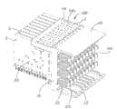
图1是本实用新型电连接器的立体组合图。 Fig. 1 is a three-dimensional assembled view of the electrical connector of the present invention. the
图2是图1所示电连接器的另一角度的立体组合图。 FIG. 2 is a perspective assembled view of another angle of the electrical connector shown in FIG. 1 . the
图3是本实用新型电连接器的部分分解图。 Fig. 3 is a partially exploded view of the electrical connector of the present invention. the
图4是本实用新型端子模组的立体图。 Fig. 4 is a perspective view of the terminal module of the present invention. the
图5是图4所示的端子模组的另一角度的立体图。 FIG. 5 is a perspective view from another angle of the terminal module shown in FIG. 4 . the
图6是图4所示的端子模组的分解图。 FIG. 6 is an exploded view of the terminal module shown in FIG. 4 . the
图7是本实用新型电连接器及其端子模组中导电端子的立体图。 Fig. 7 is a perspective view of the conductive terminals in the electric connector and the terminal module of the utility model. the
图8是图7所示的导电端子与料带相连时的示意图。 FIG. 8 is a schematic diagram when the conductive terminal shown in FIG. 7 is connected to the strip. the
【具体实施方式】【Detailed ways】
图1至图3揭示了本实用新型的电连接器100及其端子模组2。所述电连接器100包括绝缘本体1及安装于绝缘本体1上的若干端子模组2。绝缘本体1包括竖直的安装部11、自安装部11延伸的第一、第二突出部12、13及自安装 部11的上端朝另外一侧延伸的定位部14。在本实施方式中,所述第一、第二突出部12、13分别自安装部11的上、下端且朝一侧延伸而成。所述第一、第二突出部12、13之间形成暴露于空气中的收容空间110。所述安装部11设有贯穿的且与收容空间110连通的若干通孔111(参图3)。所述定位部14设有并排设置的定位槽141。 1 to 3 disclose the
请参图4至图6所示,所述端子模组2包括若干导电端子21、包覆于导电端子21上的绝缘块22及扣持于绝缘块22上的屏蔽壳体23。请参图7至图8所示,所述导电端子21是由金属料带3冲压、扭转而成。所述金属料带3为扁平状且在未冲压前包括相对设置的光滑面31。在冲压过程中,垂直光滑面31将金属料带3冲压成预定形状后遗留下来的为下料面32。若未经过特殊处理,光滑面31要比下料面32光滑得多,因此光滑面31更适合用以充当与对接连接器的导电端子配合的接触面。 Referring to FIGS. 4 to 6 , the
所述导电端子21包括蜿蜒的中间部211、自中间部211前端向前突出的接触部212及自中间部211底端向下延伸的安装脚213。所述接触部212穿过安装部11的通孔111而延伸入收容空间110内。所述中间部211包括相对设置的两个第一表面(在本实施方式中为第一光滑面)24及相对设置的且垂直第一光滑面24的两个第二表面(在本实施方式中为第一下料面)25。所述两个第一光滑面24分别与金属料带3的光滑面31一致。所述中间部211在蜿蜒过程中的任意两段的宽度及厚度均相同,以保证中间部211本身具备同样的阻抗。所述接触部212包括相对设置的两个第三表面(在本实施方式中为第二光滑面)26及相对设置且垂直第二光滑面26的两个第四表面(在本实施方式中为第二下料面)27。所述接触部212为直条状且相对于中间部211呈90度扭转。扭转的目的在于将金属料带3的光滑面31转变成用以与对接连接的导电端子(未图示)相配合的接触面(即第二光滑面26)。光滑的接触面可以降低插入力,同时保证插接的平稳性。 The
所述接触部212暴露在空气中,而中间部211是镶埋在绝缘块22内,由于空气的阻抗大而绝缘块22的阻抗小,所以为了保证在外在因素的影响下,导电端子21仍能够保持相同的阻抗,本实用新型将中间部211的宽度W1设置为小于中间部211的厚度T1,并且使中间部211的宽度W1设置为小于接触部212的宽度W2。如此设置,相当于将中间部211的宽度W1设置为比金属料带3的厚 度还要窄,便于增加中间部211本身的阻抗。另外,由于接触部212的宽度W2相对较大,进而使接触部212本身的阻抗相对于中间部211的阻抗要小。所述两个第一光滑面24之间的距离T1小于两个第二光滑面26之间的距离W2。这种设计方式可以使导电端子21在被镶埋在绝缘块22内后,各段均保持相同的阻抗且与系统阻抗相匹配。当然,做为本实用新型的进一步改进,所述中间部211的厚度T1也可以被设置为小于接触部212的厚度T2,目的与以上的设计相同。所述接触部212的后端且靠近中间部211的位置设有加厚的固定部28,所述固定部28的厚度均大于两个第一光滑面24之间的距离T1及两个第一下料面25之间的距离W1。所述固定部28固定于绝缘本体1的通孔111内,从而可以使导电端子21可以稳定固持在绝缘本体1上;另外,所述加厚的固定部28也可便接触部212相对于中间部211做扭转。 The
在本实用新型的实施方式中,所述被镶埋在绝缘块22内的中间部211被视为第一部分,而暴露于绝缘块22之外的接触部212被视为第二部分。所述导电端子21的中间部211共同的位于第一平面(未标号)内。就细部结构看,所述第一光滑面24与第一平面平行,而第一下料面25与第一平面垂直。当然,在本实用新型的其他实施方式中,所述第二部分可以为未被镶埋在绝缘块22内的其他中间部211。 In an embodiment of the present invention, the
所述绝缘块22包括一侧面221、自顶面222延伸的悬臂223及自底面224凹设的若干狭槽225。所述悬臂223的自由端设有卡扣于绝缘本体1的定位槽141内的突起2231。 The insulating
所述屏蔽壳体23包括扣持于绝缘块22的侧面221上的主体部231及自主体部231延伸的L形屏蔽部232。请参图1及图4所示,所述L形屏蔽部232延伸超过绝缘块22且延伸入收容空间110内。所述绝缘块22的侧面221设有突柱226,而屏蔽壳体23的主体部231设有与突柱226配合的定位孔233。另外,所述屏蔽壳体23的主体部231底部还设有卡持于狭槽225内的弯折部234。如此设置,便于将屏蔽壳体23稳定地扣持于绝缘块22上。 The shielding
所述导电端子21中,相互靠近的两个接触部212形成一对差分信号端子。所述L形屏蔽部232刚好位于这对差分信号端子的接触部212外围,以降低这对差分信号端子与相邻的其他差分信号端子之间的串扰。 Among the
综上所述,以上仅为本实用新型的较佳实施例而已,不应以此限制本实 用新型的范围,即凡是依本实用新型权利要求书及实用新型说明书内容所作的简单的等效变化与修饰,皆应仍属本实用新型专利涵盖的范围内。 In summary, the above are only preferred embodiments of the present utility model, and should not limit the scope of the present utility model, that is, all simple equivalents made according to the claims of the utility model and the content of the utility model description Changes and modifications should still fall within the scope covered by the utility model patent. the
Claims (10)
Priority Applications (1)
| Application Number | Priority Date | Filing Date | Title |
|---|---|---|---|
| CN2009203170117UCN201741935U (en) | 2009-12-10 | 2009-12-10 | Electric connector and terminal module of same |
Applications Claiming Priority (1)
| Application Number | Priority Date | Filing Date | Title |
|---|---|---|---|
| CN2009203170117UCN201741935U (en) | 2009-12-10 | 2009-12-10 | Electric connector and terminal module of same |
Publications (1)
| Publication Number | Publication Date |
|---|---|
| CN201741935Utrue CN201741935U (en) | 2011-02-09 |
Family
ID=43557212
Family Applications (1)
| Application Number | Title | Priority Date | Filing Date |
|---|---|---|---|
| CN2009203170117UExpired - Fee RelatedCN201741935U (en) | 2009-12-10 | 2009-12-10 | Electric connector and terminal module of same |
Country Status (1)
| Country | Link |
|---|---|
| CN (1) | CN201741935U (en) |
Cited By (30)
| Publication number | Priority date | Publication date | Assignee | Title |
|---|---|---|---|---|
| CN102709728A (en)* | 2012-06-07 | 2012-10-03 | 龙杰(苏州)精密工业有限公司 | Electronic card connector terminal and manufacturing method for same |
| CN103296537A (en)* | 2012-02-22 | 2013-09-11 | 富士康(昆山)电脑接插件有限公司 | Electric coupler and electric coupler assembly |
| US8961229B2 (en) | 2012-02-22 | 2015-02-24 | Hon Hai Precision Industry Co., Ltd. | High speed high density connector assembly |
| CN104979667A (en)* | 2014-04-03 | 2015-10-14 | 通普康电子(昆山)有限公司 | Communication connector and transmission sheet thereof |
| US9466930B2 (en) | 2013-07-19 | 2016-10-11 | Foxconn Interconnect Technology Limited | Flippable electrical connector |
| US9472911B2 (en) | 2013-07-19 | 2016-10-18 | Foxconn Interconnect Technology Limited | Flippable electrical connector with concentric inner and outer mating ports |
| US9472910B2 (en) | 2013-07-19 | 2016-10-18 | Foxconn Interconnect Technology Limited | Flippable electrical connector |
| US9484681B2 (en) | 2013-07-19 | 2016-11-01 | Foxconn Interconnect Technology Limited | Flippable electrical connector |
| US9490595B2 (en) | 2013-07-19 | 2016-11-08 | Foxconn Interconnect Technology Limited | Flippable electrical connector |
| US9490594B2 (en) | 2013-07-19 | 2016-11-08 | Foxconn Interconnect Technology Limited | Flippable electrical connector |
| US9490584B2 (en) | 2013-07-19 | 2016-11-08 | Foxconn Interconnect Technology Limited | Flippable electrical connector |
| US9490549B2 (en) | 2013-07-19 | 2016-11-08 | Foxconn Interconnect Technology Limited | Flippable electrical connector |
| US9490579B2 (en) | 2013-07-19 | 2016-11-08 | Foxconn Interconnect Technology Limited | Flippable Electrical Connector |
| US9496664B2 (en) | 2013-07-19 | 2016-11-15 | Foxconn Interconnect Technology Limited | Flippable electrical connector |
| US9496654B2 (en) | 2013-07-19 | 2016-11-15 | Foxconn Interconnect Technology Limited | Flippable electrical connector |
| US9496653B2 (en) | 2013-07-19 | 2016-11-15 | Foxconn Interconnect Technology Limited | Flippable electrical connector |
| US9502821B2 (en) | 2013-07-19 | 2016-11-22 | Foxconn Interconnect Technology Limited | Flippable electrical connector |
| US9520677B2 (en) | 2013-07-19 | 2016-12-13 | Foxconn Interconnect Technology Limited | Flippable electrical connector |
| US9660400B2 (en) | 2013-07-19 | 2017-05-23 | Foxconn Interconnect Technology Limited | Flippable electrical connector |
| US9755368B2 (en) | 2013-07-19 | 2017-09-05 | Foxconn Interconnect Technology Limited | Flippable electrical connector |
| US9762009B2 (en) | 2013-07-19 | 2017-09-12 | Foxconn Interconnect Technology Limited | Plug connector insertable in two orientations and having a metallic shield plate with arms with hook structures |
| US9843148B2 (en) | 2013-07-19 | 2017-12-12 | Foxconn Interconnect Technology Limited | Flippable electrical connector |
| US9905944B2 (en) | 2013-07-19 | 2018-02-27 | Foxconn Interconnect Technology Limited | Flippable electrical connector |
| US9912111B2 (en) | 2013-07-19 | 2018-03-06 | Foxconn Interconnect Technology Limited | Flippable electrical connector |
| US9997853B2 (en) | 2013-07-19 | 2018-06-12 | Foxconn Interconnect Technology Limited | Flippable electrical connector |
| US10170870B2 (en) | 2013-07-19 | 2019-01-01 | Foxconn Interconnect Technology Limited | Flippable electrical connector |
| CN109301544A (en)* | 2018-10-09 | 2019-02-01 | 番禺得意精密电子工业有限公司 | Electric connector |
| US10693261B2 (en) | 2013-07-19 | 2020-06-23 | Foxconn Interconnect Technology Limited | Flippable electrical connector |
| US10720734B2 (en) | 2013-07-19 | 2020-07-21 | Foxconn Interconnect Technology Limited | Flippable electrical connector |
| US10826255B2 (en) | 2013-07-19 | 2020-11-03 | Foxconn Interconnect Technology Limited | Flippable electrical connector |
- 2009
- 2009-12-10CNCN2009203170117Upatent/CN201741935U/ennot_activeExpired - Fee Related
Cited By (43)
| Publication number | Priority date | Publication date | Assignee | Title |
|---|---|---|---|---|
| CN103296537A (en)* | 2012-02-22 | 2013-09-11 | 富士康(昆山)电脑接插件有限公司 | Electric coupler and electric coupler assembly |
| US8961229B2 (en) | 2012-02-22 | 2015-02-24 | Hon Hai Precision Industry Co., Ltd. | High speed high density connector assembly |
| CN103296537B (en)* | 2012-02-22 | 2015-10-07 | 富士康(昆山)电脑接插件有限公司 | Electric connector and electric coupler component |
| CN102709728A (en)* | 2012-06-07 | 2012-10-03 | 龙杰(苏州)精密工业有限公司 | Electronic card connector terminal and manufacturing method for same |
| CN102709728B (en)* | 2012-06-07 | 2014-07-23 | 龙杰(苏州)精密工业有限公司 | Manufacturing method of electronic card connector terminal |
| US9520677B2 (en) | 2013-07-19 | 2016-12-13 | Foxconn Interconnect Technology Limited | Flippable electrical connector |
| US9660400B2 (en) | 2013-07-19 | 2017-05-23 | Foxconn Interconnect Technology Limited | Flippable electrical connector |
| US9472911B2 (en) | 2013-07-19 | 2016-10-18 | Foxconn Interconnect Technology Limited | Flippable electrical connector with concentric inner and outer mating ports |
| US9472910B2 (en) | 2013-07-19 | 2016-10-18 | Foxconn Interconnect Technology Limited | Flippable electrical connector |
| US9484681B2 (en) | 2013-07-19 | 2016-11-01 | Foxconn Interconnect Technology Limited | Flippable electrical connector |
| US9490595B2 (en) | 2013-07-19 | 2016-11-08 | Foxconn Interconnect Technology Limited | Flippable electrical connector |
| US9490594B2 (en) | 2013-07-19 | 2016-11-08 | Foxconn Interconnect Technology Limited | Flippable electrical connector |
| US9490584B2 (en) | 2013-07-19 | 2016-11-08 | Foxconn Interconnect Technology Limited | Flippable electrical connector |
| US9490549B2 (en) | 2013-07-19 | 2016-11-08 | Foxconn Interconnect Technology Limited | Flippable electrical connector |
| US9490579B2 (en) | 2013-07-19 | 2016-11-08 | Foxconn Interconnect Technology Limited | Flippable Electrical Connector |
| US9496664B2 (en) | 2013-07-19 | 2016-11-15 | Foxconn Interconnect Technology Limited | Flippable electrical connector |
| US9496654B2 (en) | 2013-07-19 | 2016-11-15 | Foxconn Interconnect Technology Limited | Flippable electrical connector |
| US9496653B2 (en) | 2013-07-19 | 2016-11-15 | Foxconn Interconnect Technology Limited | Flippable electrical connector |
| US9502821B2 (en) | 2013-07-19 | 2016-11-22 | Foxconn Interconnect Technology Limited | Flippable electrical connector |
| US9502841B2 (en) | 2013-07-19 | 2016-11-22 | Foxconn Interconnect Technology Limited | Flippable electrical connector |
| US10826255B2 (en) | 2013-07-19 | 2020-11-03 | Foxconn Interconnect Technology Limited | Flippable electrical connector |
| US9583900B2 (en) | 2013-07-19 | 2017-02-28 | Foxconn Interconnect Technology Limited | Flippable electrical connector |
| US9608391B2 (en) | 2013-07-19 | 2017-03-28 | Foxconn Interconnect Technology Limited | Flippable electrical connector |
| US10720734B2 (en) | 2013-07-19 | 2020-07-21 | Foxconn Interconnect Technology Limited | Flippable electrical connector |
| US9466930B2 (en) | 2013-07-19 | 2016-10-11 | Foxconn Interconnect Technology Limited | Flippable electrical connector |
| US9698536B2 (en) | 2013-07-19 | 2017-07-04 | Foxconn Interconnect Technology Limited | Flippable electrical connector |
| US9748702B2 (en) | 2013-07-19 | 2017-08-29 | Foxconn Interconnect Technology Limited | Flippable electrical connector |
| US9755380B2 (en) | 2013-07-19 | 2017-09-05 | Foxconn Interconnect Technology Limited | Flippable electrical connector |
| US9755368B2 (en) | 2013-07-19 | 2017-09-05 | Foxconn Interconnect Technology Limited | Flippable electrical connector |
| US9761995B2 (en) | 2013-07-19 | 2017-09-12 | Foxconn Interconnect Technology Limited | Flippable Electrical Connector |
| US9762009B2 (en) | 2013-07-19 | 2017-09-12 | Foxconn Interconnect Technology Limited | Plug connector insertable in two orientations and having a metallic shield plate with arms with hook structures |
| US9843148B2 (en) | 2013-07-19 | 2017-12-12 | Foxconn Interconnect Technology Limited | Flippable electrical connector |
| US9905944B2 (en) | 2013-07-19 | 2018-02-27 | Foxconn Interconnect Technology Limited | Flippable electrical connector |
| US9912111B2 (en) | 2013-07-19 | 2018-03-06 | Foxconn Interconnect Technology Limited | Flippable electrical connector |
| US9997853B2 (en) | 2013-07-19 | 2018-06-12 | Foxconn Interconnect Technology Limited | Flippable electrical connector |
| US10158197B2 (en) | 2013-07-19 | 2018-12-18 | Foxconn Interconnect Technology Limited | Flippable electrical connector |
| US10170870B2 (en) | 2013-07-19 | 2019-01-01 | Foxconn Interconnect Technology Limited | Flippable electrical connector |
| US10693261B2 (en) | 2013-07-19 | 2020-06-23 | Foxconn Interconnect Technology Limited | Flippable electrical connector |
| US10312646B2 (en) | 2013-07-19 | 2019-06-04 | Foxconn Interconnect Technology Limited | Flippable electrical connector |
| CN104979667B (en)* | 2014-04-03 | 2017-04-19 | 通普康电子(昆山)有限公司 | Communication connector and transmission sheet thereof |
| CN104979667A (en)* | 2014-04-03 | 2015-10-14 | 通普康电子(昆山)有限公司 | Communication connector and transmission sheet thereof |
| CN109301544A (en)* | 2018-10-09 | 2019-02-01 | 番禺得意精密电子工业有限公司 | Electric connector |
| CN109301544B (en)* | 2018-10-09 | 2020-09-25 | 番禺得意精密电子工业有限公司 | Electrical connector |
Similar Documents
| Publication | Publication Date | Title |
|---|---|---|
| CN201741935U (en) | Electric connector and terminal module of same | |
| CN201204309Y (en) | electrical connector | |
| CN201397973Y (en) | Electric connector | |
| CN102437482B (en) | Electrical connector | |
| US9325090B2 (en) | Card edge connector with a metal member | |
| US9768567B2 (en) | Flippable electrical connector | |
| US9461423B2 (en) | Electrical connector | |
| CN102263334B (en) | Electrical connector | |
| US20170033506A1 (en) | Electrical connector having good anti-emi perfprmance | |
| CN104037550B (en) | Electric connector | |
| CN202444086U (en) | Connector | |
| CN105390884A (en) | Contact module and electric connector | |
| TWI740511B (en) | Full-shielding cable connector and cable plug thereof | |
| CN209880871U (en) | First terminal set, first terminal module, first connector and connector assembly | |
| CN110086018B (en) | Electrical connector | |
| US20120108110A1 (en) | Electrical connector | |
| CN207490220U (en) | Connector | |
| CN104124550B (en) | Electric connector | |
| CN205646372U (en) | Electric connector assembly | |
| CN201766207U (en) | electrical connector socket | |
| CN101615734A (en) | Cable Connector Assembly | |
| CN204793281U (en) | Electric connector | |
| CN203690564U (en) | Electric connector | |
| CN201160168Y (en) | electrical connector | |
| CN111342272B (en) | An electrical connector |
Legal Events
| Date | Code | Title | Description |
|---|---|---|---|
| C14 | Grant of patent or utility model | ||
| GR01 | Patent grant | ||
| CF01 | Termination of patent right due to non-payment of annual fee | Granted publication date:20110209 Termination date:20151210 | |
| EXPY | Termination of patent right or utility model |