CN201730951U - A two-way hinge that can rotate 360 degrees forward and reverse - Google Patents
A two-way hinge that can rotate 360 degrees forward and reverseDownload PDFInfo
- Publication number
- CN201730951U CN201730951UCN2010201611230UCN201020161123UCN201730951UCN 201730951 UCN201730951 UCN 201730951UCN 2010201611230 UCN2010201611230 UCN 2010201611230UCN 201020161123 UCN201020161123 UCN 201020161123UCN 201730951 UCN201730951 UCN 201730951U
- Authority
- CN
- China
- Prior art keywords
- pair
- piece
- ring portion
- degrees
- angle switching
- Prior art date
- Legal status (The legal status is an assumption and is not a legal conclusion. Google has not performed a legal analysis and makes no representation as to the accuracy of the status listed.)
- Expired - Lifetime
Links
Images


Landscapes
- Displays For Variable Information UsingMovable Means (AREA)
Abstract
Description
Translated fromChinese技术领域technical field
本实用新型关于一种可正及反向旋转360度的双向枢钮器。The utility model relates to a two-way hinge device capable of forward and reverse rotation of 360 degrees.
背景技术Background technique
在折叠式电子设备之中,具有一上盖及一底座,例如笔记型电脑具有一显示荧幕及一键盘部。为了上盖及底座可相对开启或闭合,必需设置枢钮器。Among the foldable electronic devices, there is an upper cover and a base, for example, a notebook computer has a display screen and a keyboard. In order that the upper cover and the base can be relatively opened or closed, a hinge must be provided.
有时为了使上盖能在垂直面上旋转,例如笔记型电脑将显示荧幕开启后旋转以向周围的展示,而有已知的双向旋转枢钮器的设计。为了达到上盖在垂直面上旋转至定位时,能产生一定位功能,常在双向旋转枢钮器中设置有定位机构,且为了防止上盖在垂直面上旋转过度而有限位装置,以限制旋转角度。例如,中国台湾发明专利证书号数I296680「电子设备的双轴铰链装置」前案,提供了一种电子设备的双轴铰链装置,该装置使第2部件相对于第1部件能够开闭,通常,第2部件相对于第1部件能够保持在固定位置,但是根据需要,第2部件相对于第1部件能够沿左右任一方向转动,该装置具有第1轴和第2轴,构成电子设备的,第2部件相对于第1部件绕上述第1轴转动而朝垂直方向开闭,并且使上述第2部件绕上述第2轴朝水平方向转动,并且还具有有位于上述第1轴处的第2部件的垂直方向转动控制机构,以及位于上述第2轴处的上述第2部件的水平转动控制机构,在上述垂直方向转动控制机构的支撑部件与把该支撑部件安装成朝水平方向能够转动的上述水平方向转动控制机构的安装部件之间,设有可动挡块机构,通过该可动挡块机构,将上述第2部件相对于上述第1部件的水平方向的转动限制在预定角度,且当上述第2部件相对于上述第1部件进一步转动时,则解除上述限制,上述第2部件朝同一方向进一步转动。Sometimes in order to make the upper cover rotate on the vertical plane, for example, the display screen of a notebook computer is turned on and then rotated to display around, and there is a known design of a bidirectional rotating hinge. In order to achieve a positioning function when the upper cover is rotated to the position on the vertical plane, a positioning mechanism is often provided in the two-way rotation hinge, and in order to prevent the upper cover from excessively rotating on the vertical plane, there is a limit device to limit Rotation angle. For example, the previous case of Taiwan Invention Patent Certificate No. I296680 "Double-axis hinge device for electronic equipment" provides a double-axis hinge device for electronic equipment. The device enables the second part to be opened and closed relative to the first part. , the second part can be kept in a fixed position relative to the first part, but according to needs, the second part can rotate in any direction from left to right relative to the first part, the device has a first shaft and a second shaft, and constitutes the , the second member rotates around the first axis relative to the first member to open and close in the vertical direction, and makes the second member rotate in the horizontal direction around the second axis, and also has a first The vertical rotation control mechanism of two components, and the horizontal rotation control mechanism of the second component located at the second axis, the support component of the vertical rotation control mechanism and the support component installed so as to be rotatable in the horizontal direction A movable stopper mechanism is provided between the mounting parts of the above-mentioned horizontal direction rotation control mechanism, and the horizontal rotation of the above-mentioned second member relative to the above-mentioned first member is limited to a predetermined angle by the movable stopper mechanism, and When the second member is further rotated relative to the first member, the restriction is released, and the second member is further rotated in the same direction.
又例如,在中国台湾新型专利证书号数M328762「枢纽器」前案中,提供了一种枢钮器,其包含一连接荧幕的荧幕接座,该接座下方设有一枢轴,该枢轴上枢设有一连接本体的本体接座,本体接座上设有一限位部,另于本体接座上设有一枢转组件,其套设于轴杆并包含有一外、内枢片;外枢片中央设有一枢孔,且周缘处设有对应限位部的限位片,且枢孔的环壁面上设有放射状缺口;内枢片枢设于外枢片的枢孔内,并设有对应外枢片的缺口的挡块;而藉内枢片的挡块于外枢片的缺口中枢转,可令本枢钮器的水平方向枢转达到360度。For another example, in the previous case of Taiwan New Patent Certificate No. M328762 "Hinge Device", a hinge device is provided, which includes a screen socket connected to the screen, and a pivot is arranged below the socket. A body seat connecting the body is pivotally arranged on the pivot shaft, a position limiting portion is provided on the body seat, and a pivot assembly is arranged on the body seat, which is sleeved on the shaft rod and includes an outer and an inner pivot piece; There is a pivot hole in the center of the outer pivot piece, and a limit piece corresponding to the limit portion is provided at the periphery, and radial gaps are provided on the ring wall of the pivot hole; the inner pivot piece is pivotally arranged in the pivot hole of the outer pivot piece, and A stopper corresponding to the notch of the outer pivot piece is provided; and the pivot of the hinge device in the horizontal direction can reach 360 degrees by pivoting the stopper of the inner pivot piece in the notch of the outer pivot piece.
又例如,在中国台湾新型专利证书号数M357838「枢纽器及具有枢纽器的电子装置」前案中,提供了一种枢钮器及具有枢钮器的电子装置,该电子装置包含有一底座-一上盖、以及一连接该底座与上盖的枢钮器,其中,该枢钮器包含有一第一致动件及一第二致动件,该第一致动件具有一与该第二致动件相推抵而可移动适当距离的导引单元,因此该上盖双向旋转至一定角度时,该第二致动件会与该导引单元相抵接,进一步推动该导引单元,使该上盖达到双向旋转360度且零视觉死角,所以可移动的导引单元的设计,除了可以限位该上盖的旋转角度以保护线路外,尚可以解决该枢钮器旋转死角的问题。For another example, in the previous case of Taiwan New Patent Certificate No. M357838 "Hinge Device and Electronic Device with a Hinge Device", a hinge device and an electronic device with a hinge device are provided. The electronic device includes a base- An upper cover, and a hinge device connecting the base and the upper cover, wherein the hinge device includes a first actuator and a second actuator, the first actuator has a The actuating member pushes against the guiding unit that can move an appropriate distance, so when the upper cover rotates to a certain angle in both directions, the second actuating member will abut against the guiding unit, further pushing the guiding unit, so that The upper cover can rotate 360 degrees in both directions and has zero visual dead angle. Therefore, the design of the movable guide unit can not only limit the rotation angle of the upper cover to protect the circuit, but also solve the problem of the dead angle of the hinge.
在相关的前案中所揭露的双向枢钮器,虽皆具有可旋转360度、定位功能及限位功能,但其结构中,提供限位功能的限位装置结构复杂,制造困难且组装不易;尤其在前案中,皆采用了挡块在基座上可移动方式来达到360度旋转,这将使得挡块在组装时费工费时不利生产,且稳定度较差,易发生卡死情况,有待改善。Although the two-way hinges disclosed in the related previous cases all have 360-degree rotation, positioning function and limit function, the structure of the limit device providing the limit function is complex, difficult to manufacture and difficult to assemble. ; Especially in the previous case, the stopper is movable on the base to achieve 360-degree rotation, which will make the stopper labor-intensive and time-consuming during assembly, which is not conducive to production, and the stability is poor, and it is prone to jamming ,needs to be improved.
发明内容Contents of the invention
缘此,本实用新型的目的在于,提供了一种可正及反向旋转360度的双向枢钮器,其能应用于具有上盖及底座的折叠式电子设备中,使得上盖可相对底座开启以及正及反向能旋转360度,且结构简单,制造和组装简便,不易卡死。For this reason, the purpose of the utility model is to provide a bi-directional hinge device that can rotate forward and reverse 360 degrees, which can be applied to a foldable electronic device with an upper cover and a base, so that the upper cover can be rotated relative to the base It can be opened and rotated 360 degrees forward and reverse, and has a simple structure, easy manufacture and assembly, and is not easy to be stuck.
为实现上述目的,本实用新型公开了一种可正及反向旋转360度的双向枢钮器,被设置于一具有一上盖及一底座的折叠式电子设备中;其特征在于包括:In order to achieve the above purpose, the utility model discloses a two-way hinge that can rotate forward and reverse 360 degrees, which is set in a foldable electronic device with an upper cover and a base; it is characterized in that it includes:
一固定架,组装于该底座内,具有一轴孔,并在该轴孔周缘向上形成一对固定挡块;另于该轴孔周缘向径向外方向相对形成一对定位缺口;A fixing frame, assembled in the base, has a shaft hole, and a pair of fixed stops are formed upward on the periphery of the shaft hole; in addition, a pair of positioning notches are formed on the periphery of the shaft hole radially outward;
一旋转架,其上方在水平方向对称组接一对使该上盖能相对该底座开启闭合的枢转机构,且每一该枢转机构分别连接一与该上盖组接的架体;其下方在垂直方向形成一穿过该固定架的轴孔而可相对旋转且使该上盖能在垂直面上旋转的垂直轴;该垂直轴自一凸缘向下延伸;A swivel frame, on which a pair of pivoting mechanisms are assembled symmetrically in the horizontal direction so that the upper cover can be opened and closed relative to the base, and each of the pivoting mechanisms is respectively connected to a frame body assembled with the upper cover; A vertical shaft is formed below in the vertical direction to pass through the shaft hole of the fixing frame and to be relatively rotatable and to enable the upper cover to rotate on a vertical plane; the vertical shaft extends downward from a flange;
一限位片,具有一与该垂直轴一同旋转的环部,并于该限位片的环部上向下形成一对角度切换凸块;A limiting piece has a ring portion that rotates with the vertical shaft, and a pair of angle switching projections are formed downward on the ring portion of the limiting piece;
一止挡片,具有一套接于该垂直轴上但不与该垂直轴一同旋转的环部;在该止挡片的环部周缘向外形成一与该固定架的该对固定挡块进行限位的限位部,且于该止挡片的环部上形成一对供该对角度切换凸块伸入以进行角度切换的弧形角度切换槽;A stop piece has a ring portion that is sleeved on the vertical shaft but does not rotate together with the vertical shaft; a ring portion that is connected with the pair of fixed blocks of the fixed frame is formed outwardly on the periphery of the stop piece. A position-limiting portion, and a pair of arc-shaped angle switching slots are formed on the ring portion of the stop piece for the pair of angle switching protrusions to extend into for angle switching;
一定位片,设置于该固定架的轴孔下方,具有一与该垂直轴一同旋转的环部;该定位片的环部向上形成一对在该垂直轴旋转至0或180度时卡入该固定架该对定位缺口内的定位凸点;A positioning piece, which is arranged under the shaft hole of the fixed frame, has a ring portion that rotates together with the vertical shaft; the ring portion of the positioning piece upwards to form a pair that snaps into the vertical shaft when the vertical shaft rotates to 0 or 180 degrees. The positioning protrusions in the pair of positioning notches of the fixing frame;
一弹力环,套设于该垂直轴上以邻接于该固定架的轴孔下方;及an elastic ring is sleeved on the vertical shaft so as to be adjacent to the bottom of the shaft hole of the fixing frame; and
一固定结合于该垂直轴的底面从而使该弹力环对该固定架、旋转架、限位片、止挡片、定位片产生压迫力并形成该旋转架旋转的扭力的固定装置。A fixing device that is fixedly combined with the bottom surface of the vertical shaft so that the elastic ring produces a pressing force on the fixed frame, the rotating frame, the limiting piece, the stop piece, and the positioning piece and forms a torsion force for the rotating frame.
其中,该垂直轴表面形成数个结合槽,而该限位片的环部内具有与该结合槽对应的凸部,且该定位片环部内亦具有与该结合槽对应的凸部。Wherein, several combination grooves are formed on the surface of the vertical axis, and the ring portion of the limiting piece has protrusions corresponding to the combination grooves, and the ring portion of the positioning piece also has protrusions corresponding to the combination grooves.
其中,该限位片环部的该对角度切换凸块设置于该限位片环部内及外缘间的中间位置,而该止挡片环部的该对弧形角度切换槽亦设置于该止挡片环部内及外缘间的中间位置。Wherein, the pair of angle switching protrusions of the ring portion of the limiting plate are arranged at the middle position between the inner portion of the ring portion of the limiting plate and the outer edge, and the pair of arc-shaped angle switching grooves of the ring portion of the stopper plate are also arranged on the The middle position between the inner and outer edges of the stop ring.
其中,该止挡片的限位部上固定设置一配合该折叠式电子设备的底座上开设的一个负180度显示孔及一个正180度显示孔的且在该旋转架旋转接近负180及正180度时分别位在该负180度显示孔及该正180度显示孔下方以指示旋转角度的显示块。Wherein, a negative 180-degree display hole and a positive 180-degree display hole are fixedly arranged on the limit portion of the stopper to match the base of the foldable electronic device, and when the rotating frame rotates close to negative 180 and positive When 180 degrees, the display blocks are respectively located under the negative 180 degree display hole and the positive 180 degree display hole to indicate the rotation angle.
其中,该止挡片的限位部上开设有一对穿孔,而该显示块底部设有一对固定柱,该对固定柱伸入该对穿孔内。Wherein, a pair of perforations are opened on the limiting portion of the stop piece, and a pair of fixing posts are provided at the bottom of the display block, and the pair of fixing posts extend into the pair of through holes.
其中,该显示块表面被荧光处理。Wherein, the surface of the display block is treated with fluorescence.
其中,该限位片环部的该对角度切换凸块设置于该限位片环部内缘旁边位置,而该止挡片环部的该对弧形角度切换槽亦设置于该止挡片环部内缘旁边位置。Wherein, the pair of angle switching protrusions of the ring portion of the limiting plate are arranged at the position next to the inner edge of the ring portion of the limiting plate, and the pair of arc-shaped angle switching grooves of the ring portion of the stopper plate are also arranged on the ring portion of the stopper plate next to the inner edge of the interior.
其中,该限位片环部的该对角度切换凸块设置于该限位片环部外缘旁边位置,而该止挡片环部的该对弧形角度切换槽亦设置于该止挡片环部外缘旁边位置。Wherein, the pair of angle switching protrusions of the ring portion of the limiting plate are arranged at the position beside the outer edge of the ring portion of the limiting plate, and the pair of arc-shaped angle switching grooves of the ring portion of the stopper plate are also arranged on the stopper plate Next to the outer edge of the ring.
通过上述结构,本实用新型的双向枢钮器中的旋转架以0度为基准,顺时钟及逆时钟旋转正及负180度,即枢钮器的旋转架可被限制于正及反向旋转360度,不会发生过度旋转的问题;且藉由该限位片上的一对角度切换凸块与该止挡片上的一对角度切换滑槽进行角度切换,使止挡片的限位部能与固定架上一对固定挡块达到360度旋转限位功能。由于限位片及止挡片皆为环状的类似大小结构,可很容易的组装于旋转架的垂直轴上,这将使得枢钮器的安装大为简化,且旋转顺畅,不易发生卡死的缺点;进者,在该止挡片的限位部设置一显示块,该显示块配合折叠式电子设备的底座上开设的正及负180度显示孔,在该旋转架旋转接近正及负180度时,该显示块在正或负180度显示孔下方,以指示旋转角度,提醒使用者不能再继续转动而要反转了。Through the above structure, the rotating frame in the two-way hinge device of the present invention is based on 0 degrees, clockwise and counterclockwise rotating positive and negative 180 degrees, that is, the rotating frame of the hinge device can be limited to positive and reverse rotation 360 degrees, the problem of over-rotation will not occur; and through the angle switching between the pair of angle switching protrusions on the limit piece and the pair of angle switching chute on the stop piece, the limit part of the stop piece can be It can achieve 360-degree rotation limit function with a pair of fixed stops on the fixed frame. Since both the limit piece and the stop piece are ring-shaped and similar in size, they can be easily assembled on the vertical axis of the rotating frame, which greatly simplifies the installation of the hinge, and the rotation is smooth, and it is not easy to get stuck In addition, a display block is set on the limit part of the stopper, and the display block cooperates with the positive and negative 180-degree display holes opened on the base of the foldable electronic device, and when the rotating frame rotates close to the positive and negative When 180 degrees, the display block is below the positive or negative 180 degree display hole to indicate the rotation angle, reminding the user that it can no longer continue to rotate and will reverse.
以下,将依据图面所示的实施例而详加说明本实用新型的结构特点及使用功效。Hereinafter, the structural features and usage effects of the present utility model will be described in detail according to the embodiments shown in the drawings.
附图说明Description of drawings
图1代表本实用新型组装于一折叠式电子设备的示意图,Fig. 1 represents the schematic diagram that the utility model is assembled in a foldable electronic device,
图2代表本实用新型的立体图,Fig. 2 represents the perspective view of the present utility model,
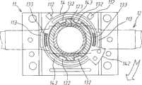
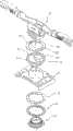
图3代表本实用新型的分解图,Fig. 3 represents the exploded view of the utility model,
图3A为图3中沿A A剖面放大视图,Fig. 3 A is an enlarged view along the section A A in Fig. 3,
图4代表本实用新型的平面及部份剖视图,Fig. 4 represents the plane of the present utility model and partial sectional view,
图5代表图4中沿A A的剖面图,Fig. 5 represents the sectional view along A A in Fig. 4,
图6至图8代表本实用新型逆时钟旋转的动作示意图,Fig. 6 to Fig. 8 represent the action schematic diagram of counterclockwise rotation of the utility model,
图6A至图8A配合图6至图8,以相对显示定位片与定位缺口的相关位置图,Fig. 6A to Fig. 8A cooperate with Fig. 6 to Fig. 8 to relatively show the relative positions of the positioning piece and the positioning notch,
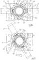
图9代表本实用新型组装于折叠式电子设备底座内的平面示意图,以展示逆时钟旋转时显示块指示角度功能,Fig. 9 represents the schematic plan view of the utility model assembled in the base of the foldable electronic equipment, to show the function of indicating the angle of the display block when rotating counterclockwise,
图10至图12代表本实用新型顺时钟旋转的动作示意图,Fig. 10 to Fig. 12 represent the action diagram of clockwise rotation of the utility model,
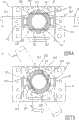
图13代表本实用新型组装于折叠式电子设备底座内的平面示意图,以展示顺时钟旋转时显示块指示角度功能,Fig. 13 represents the schematic plan view of the utility model assembled in the base of the foldable electronic equipment, to show the function of indicating the angle of the display block when rotating clockwise,
图14代表本实用新型第二种实施例的分解图,Fig. 14 represents the exploded view of the second embodiment of the utility model,
图15代表本实用新型第三种实施例的分解图。Fig. 15 represents an exploded view of the third embodiment of the present invention.
具体实施方式Detailed ways
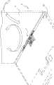
请参见图1,为本实用新型提供了一种可正及反向旋转360度的双向枢钮器1,被设置于一具有一上盖91及一底座92的折叠式电子设备9中,例如笔记型电脑等,以提供上盖91除了可相对底座92开启外,上盖91也可在开启至垂直位置时,旋转360度,如图1中箭头所示。Please refer to Fig. 1, the utility model provides a kind of two-
参见图2至图5,本实用新型所提供的可正及反向旋转360度的双向枢钮器1,主要由一固定架11、一旋转架12、一限位片13、一止挡片14、一定位片15、一弹力环16及一固定装置17所构成。Referring to Fig. 2 to Fig. 5, the two-
固定架11组装于折叠式电子设备9的底座92内,具有一轴孔111,并在该轴孔111周缘向上形成一对固定挡块112;另,于该轴孔111周缘向径向外方向相对形成一对定位缺口113。The
旋转架12上方在水平方向对称组接一对枢转机构121,且每一枢转机构121分别连接一与折叠式电子设备9的上盖91组接的架体122,使上盖91能相对底座92开启闭合。旋转架12下方在垂直方向形成一垂直轴123,该垂直轴123表面形成数个结合槽124,且垂直轴123穿过固定架11的轴孔111而可相对旋转,使上盖91能在开启至垂直面上旋转。垂直轴123自一凸缘125向下延伸。A pair of pivoting mechanisms 121 are assembled symmetrically on the top of the rotating
限位片13具有一环部131,环部131内具有与结合槽124对应的凸部132,而可与垂直轴123一同旋转;另,参见图3A,于环部131上向下形成一对角度切换凸块133。The limiting
止挡片14具有一环部141以套接于垂直轴123上,但不与垂直轴123一同旋转。在环部141周缘向外形成一限位部142,且于环部141上形成一对弧形角度切换槽143,该对角度切换槽143供该对角度切换凸块133伸入以进行角度切换。而限位部142与固定架11的该对固定挡块112进行限位。The
定位片15设置于固定架11的轴孔111下方,具有一环部151,该环部151内亦具有与该结合槽124对应的凸部152,而可与垂直轴123一同旋转。环部151上设有一对定位凸点153,该对定位凸点153在垂直轴123旋转至0或正负180度时卡入固定架11的该对定位缺口113内,以达到定位功能,可参见图5所示。The
弹力环16套设于垂直轴123上以邻接于固定架11的轴孔111下方。固定装置17,例如图中所示为一个螺帽结构,以固定结合于垂直轴123的底面,使弹力环16对该固定架11、旋转架12、限位片13、止挡片14、定位片15产生压迫力,可参见图4所示,以形成该旋转架12旋转的扭力。The
在图3所示,限位片13环部131的该对角度切换凸块133设置于限位片13环部131内及外缘间的中间位置,而止挡片14环部141的该对弧形角度切换槽143亦设置于止挡片14环部141内及外缘间的中间位置。As shown in FIG. 3 , the pair of
参见图6至图8,为本实用新型的旋转架12逆时钟旋转的动作示意图。当旋转架12的垂直轴123在0度位置时(即旋转架12在水平位置),如图6所示,限位片13的该对角度切换凸块133位在止挡片14的该对角度切换槽143一端,而止挡片14的限位部142未与固定架11上的固定挡块112接触,故旋转架12可逆时钟旋转。参见图6A,定位片15的定位凸点153卡入固定架11的定位缺口113,以在0度形成定位作用。Referring to FIG. 6 to FIG. 8 , they are schematic diagrams of counterclockwise rotation of the
如图7所示,当旋转架12逆时钟方向旋转120度时,垂直轴123上的结合槽124卡入限位片13的凸部132而会带动限位片13一同转动,使限位片13的角度切换凸块133在止挡片14的角度切换槽143滑移,至角度切换槽143的另一端,以进行角度切换动作。参见图7A所示,垂直轴123上的结合槽124卡入定位片15的凸部152而会带动定位片15一同转动,使定位片15的定位凸点153脱离固定架11的定位缺口113,而解除定位功能。As shown in Figure 7, when the
当旋转架12继续逆时钟旋转至180度时,如图8所示,垂直轴123继续带动限位片13一同转动,而限位片13的角度切换凸块133抵挡于止挡片14的角度切换槽143末端而带动止挡片14一同转动,使得止挡片14的限位部142与固定架11的其中之一固定挡块112抵挡(如图8中所示右侧的固定挡块112),产生限位功能,以限制旋转架12不能继续逆时钟旋转。参见图8A所示,垂直轴123也继续带动定位片15一同转动,使定位片15的定位凸点153再度卡入固定架11的定位缺口113内,以在负180度形成定位作用。When the
参见图9所示,枢钮器1在止挡片14的限位部142上固定设置一显示块144(配合图3所示),该显示块144配合折叠式电子设备9的底座92上开设的一个负180度显示孔921,在该旋转架12旋转接近负180度时,该显示块144位在负180度显示孔921下方,以指示旋转角度,提醒使用者不能再继续逆时钟转动,而要顺时钟反转了。Referring to Fig. 9, the
参考图3所示,止挡片14的限位部142上开设有一对穿孔145,而显示块144底部设有一对固定柱146,该对固定柱146伸入该对穿孔145内以形成固定作用。另,显示块144表面最好是被荧光处理,以达到醒目效果。Referring to Fig. 3, a pair of perforations 145 are provided on the limiting
参见图10至图12,为本实用新型旋转架12顺时钟旋转的动作示意图。当旋转架12的垂直轴123在0度位置时(即旋转架12在水平位置),如图10所示(与图6相同),限位片13的该对角度切换凸块133位在止挡片14的该对角度切换槽143一端,而止挡片14的限位部142未与固定架11上的固定挡块112接触,故旋转架12可顺时钟旋转。与图6A图相同,定位片15的定位凸点153卡入固定架11的定位缺口113,以在0度形成定位作用。Referring to FIG. 10 to FIG. 12 , it is a schematic diagram of the clockwise rotation of the
如图11所示,当旋转架12顺时钟方向旋转60度时,垂直轴123上的结合槽124卡入限位片13的凸部132而会带动限位片13一同转动,而限位片13的角度切换凸块133抵挡于止挡片14的角度切换槽143末端而带动止挡片14一同转动。与图7A所示相同,垂直轴123上的结合槽124卡入定位片15的凸部152而带动定位片15一同转动,使定位片15的定位凸点153脱离固定架11的定位缺口113,从而解除定位功能。As shown in Figure 11, when the
当旋转架12继续顺时钟旋转至正180度时,如图12所示,垂直轴123继续带动限位片13一同转动,而限位片13的角度切换凸块133抵挡于止挡片14的角度切换槽143末端而带动止挡片14一同转动,至旋转架12旋转至正180度,使得止挡片14的限位部142与固定架11的另一固定挡块112抵挡(如图12中所示左侧的固定挡块112),产生限位功能,以限制旋转架12不能继续顺时钟旋转。与图8A所示相同,垂直轴123也继续带动定位片15一同转动,使定位片15的定位凸点153再度卡入固定架11的定位缺口113内,以在正180度形成定位作用。When the
参见图13所示,枢钮器1在止挡片14的限位部142上的显示块144配合折叠式电子设备9的底座92上开设的一个正180度显示孔922,在该旋转架12旋转接近正180度时,该显示块144位在正180度显示孔922下方,以指示旋转角度,提醒使用者不能再继续顺时钟转动,而要逆时钟反转了。Referring to FIG. 13 , the
本实用新型枢钮器1中的旋转架12可以0度为基准,顺时钟及逆时钟旋转正及负180度,意即枢钮器1的旋转架12可被限制于正及反向旋转360度,不会发生过度旋转的问题。The
本实用新型的枢钮器1,采用了限位片13的角度切换凸块133与止挡片14的角度切换滑槽143进行角度切换,使止挡片14的限位部142能与固定架11上的该对固定挡块112达到可正及反向旋转360度的限位功能;由于限位片13及止挡片14皆为环状的类似大小结构,这将使得枢钮器1的安装大为简化,且旋转顺畅,不易发生卡死的缺点。The
进者,在图14及图15所示的本实用新型第二种及第三种实施例,大致与图3所示第一种实施例相类似,具有一固定架11、一旋转架12、一限位片13、一止挡片14、一定位片15、及一弹力环16一固定装置17。但在图14所示第二种实施例中,限位片13环部131的该对角度切换凸块133设置于该限位片13环部131内缘旁边位置,而止挡片14环部141的该对弧形角度切换槽143亦设置于止挡片14环部141内缘旁边位置。Furthermore, the second and third embodiments of the utility model shown in Figure 14 and Figure 15 are roughly similar to the first embodiment shown in Figure 3, and have a fixed
图15所示第三种实施例中,限位片13环部131的该对角度切换凸块133设置于该限位片13环部131外缘旁边位置,而止挡片14环部141的该对弧形角度切换槽143亦设置于止挡片14环部141外缘旁边位置。In the third embodiment shown in Fig. 15, the pair of
综上所陈,本实用新型所提供的可正及反向旋转360度的双向枢钮器,完全符合专利要件,爰依法提出申请。In summary, the two-way hinge device provided by the utility model, which can rotate 360 degrees positively and reversely, fully complies with the requirements of the patent, and an application is filed according to law.
Claims (8)
Translated fromChinesePriority Applications (1)
| Application Number | Priority Date | Filing Date | Title |
|---|---|---|---|
| CN2010201611230UCN201730951U (en) | 2010-04-16 | 2010-04-16 | A two-way hinge that can rotate 360 degrees forward and reverse |
Applications Claiming Priority (1)
| Application Number | Priority Date | Filing Date | Title |
|---|---|---|---|
| CN2010201611230UCN201730951U (en) | 2010-04-16 | 2010-04-16 | A two-way hinge that can rotate 360 degrees forward and reverse |
Publications (1)
| Publication Number | Publication Date |
|---|---|
| CN201730951Utrue CN201730951U (en) | 2011-02-02 |
Family
ID=43522108
Family Applications (1)
| Application Number | Title | Priority Date | Filing Date |
|---|---|---|---|
| CN2010201611230UExpired - LifetimeCN201730951U (en) | 2010-04-16 | 2010-04-16 | A two-way hinge that can rotate 360 degrees forward and reverse |
Country Status (1)
| Country | Link |
|---|---|
| CN (1) | CN201730951U (en) |
Cited By (2)
| Publication number | Priority date | Publication date | Assignee | Title |
|---|---|---|---|---|
| CN104898767A (en)* | 2014-03-03 | 2015-09-09 | 宏碁股份有限公司 | Electronic device and its component positioning module |
| CN107918448A (en)* | 2016-10-11 | 2018-04-17 | 昆山纬绩资通有限公司 | Hinge mechanism and portable electron device |
- 2010
- 2010-04-16CNCN2010201611230Upatent/CN201730951U/ennot_activeExpired - Lifetime
Cited By (4)
| Publication number | Priority date | Publication date | Assignee | Title |
|---|---|---|---|---|
| CN104898767A (en)* | 2014-03-03 | 2015-09-09 | 宏碁股份有限公司 | Electronic device and its component positioning module |
| CN104898767B (en)* | 2014-03-03 | 2018-04-27 | 宏碁股份有限公司 | Electronic device and component positioning module thereof |
| CN107918448A (en)* | 2016-10-11 | 2018-04-17 | 昆山纬绩资通有限公司 | Hinge mechanism and portable electron device |
| CN107918448B (en)* | 2016-10-11 | 2019-09-13 | 昆山纬绩资通有限公司 | Hinge mechanism and portable electronic device |
Similar Documents
| Publication | Publication Date | Title |
|---|---|---|
| US9714533B2 (en) | Biaxial hinge and terminal device using the same | |
| CN103291737B (en) | Card lock double axis hub | |
| TWI682265B (en) | Pivoting mechanism and electronic device | |
| CN104832531B (en) | Double-shaft hinge and terminal machine using same | |
| CN101451573B (en) | Hinge mechanism | |
| TWI553449B (en) | Folding device | |
| CN104863956B (en) | Double-shaft hinge and terminal machine using same | |
| TWM400736U (en) | 360 degrees rotatable bi-directional hinge | |
| TW201329355A (en) | Hinge device, foldable apparatus, and portable terminal | |
| US7987559B2 (en) | Hinge assembly with restricting unit | |
| CN103307094B (en) | Card lock double axis hub | |
| TWI498713B (en) | Electronic device with rotary positioning function | |
| TWI463078B (en) | Card lathe biaxial hub | |
| CN103322030B (en) | Rotary stop type double axis hub | |
| CN201730951U (en) | A two-way hinge that can rotate 360 degrees forward and reverse | |
| TWI490420B (en) | Rotary stop type biaxial hub | |
| CN105700633A (en) | Quick release rotating mechanism with positioning function and electronic device with positioning rotating door panel | |
| CN201391539Y (en) | hub | |
| CN201779130U (en) | Dual-axis hinge with rotatable displacement | |
| TWM527197U (en) | Hinge with transmission function | |
| CN201606398U (en) | Multi-angle automatic closing concave-convex wheel assembly | |
| CN201705802U (en) | Pivot device with positioning and resetting functions | |
| CN2916235Y (en) | Rotary hub | |
| JP4034234B2 (en) | HINGE DEVICE AND ELECTRONIC DEVICE USING HINGE DEVICE | |
| CN203756719U (en) | Hinge mechanism and notebook computer using same |
Legal Events
| Date | Code | Title | Description |
|---|---|---|---|
| C14 | Grant of patent or utility model | ||
| GR01 | Patent grant | ||
| CX01 | Expiry of patent term | Granted publication date:20110202 | |
| CX01 | Expiry of patent term |