CN201663252U - Electrical connector and its terminal structure - Google Patents
Electrical connector and its terminal structureDownload PDFInfo
- Publication number
- CN201663252U CN201663252UCN2009202914045UCN200920291404UCN201663252UCN 201663252 UCN201663252 UCN 201663252UCN 2009202914045 UCN2009202914045 UCN 2009202914045UCN 200920291404 UCN200920291404 UCN 200920291404UCN 201663252 UCN201663252 UCN 201663252U
- Authority
- CN
- China
- Prior art keywords
- terminal
- row
- springing
- fixed part
- width
- Prior art date
- Legal status (The legal status is an assumption and is not a legal conclusion. Google has not performed a legal analysis and makes no representation as to the accuracy of the status listed.)
- Expired - Fee Related
Links
- 239000002184metalSubstances0.000claimsabstractdescription70
- 238000004080punchingMethods0.000claimsabstractdescription35
- 210000001503jointAnatomy0.000claimsdescription12
- 238000003780insertionMethods0.000claimsdescription7
- 230000037431insertionEffects0.000claimsdescription7
- 238000010276constructionMethods0.000claims18
- 206010058109HangnailDiseases0.000claims2
- 238000004519manufacturing processMethods0.000description36
- 238000010586diagramMethods0.000description16
- 239000000463materialSubstances0.000description13
- UQMRAFJOBWOFNS-UHFFFAOYSA-Nbutyl 2-(2,4-dichlorophenoxy)acetateChemical compoundCCCCOC(=O)COC1=CC=C(Cl)C=C1ClUQMRAFJOBWOFNS-UHFFFAOYSA-N0.000description7
- 229910000679solderInorganic materials0.000description7
- 239000002699waste materialSubstances0.000description5
- 241001391944Commicarpus scandensSpecies0.000description4
- 230000000694effectsEffects0.000description3
- ATJFFYVFTNAWJD-UHFFFAOYSA-NTinChemical compound[Sn]ATJFFYVFTNAWJD-UHFFFAOYSA-N0.000description1
- 230000015572biosynthetic processEffects0.000description1
- 238000000034methodMethods0.000description1
Images


Landscapes
- Manufacturing Of Electrical Connectors (AREA)
Abstract
Description
Translated fromChinese【技术领域】【Technical field】
本实用新型是有关于一种电连接器,特别是关于一种端子在冲压制造非常节省材料的电连接器。 The utility model relates to an electric connector, in particular to an electric connector in which terminals are very material-saving in stamping manufacturing. the
【背景技术】【Background technique】
电连接器的端子在制造上是以金属片冲压,冲压完成的端子是依电连接器的端子间距而间隔排列连接于一料带上,如此整排的端子可一次组装在电连接器的塑胶座体上。 The terminals of the electrical connector are stamped with metal sheets in manufacturing, and the stamped terminals are arranged at intervals according to the terminal spacing of the electrical connector and connected to a strip, so that the entire row of terminals can be assembled on the plastic of the electrical connector at one time. On the seat body. the
上述整排连续排列端子在冲压制造上,两相邻端子的间隔区域则是金属片打掉材料而形成,故此部份则成废料,因此,若要节省端子冲压上的成本则需减少废料形成。 In the stamping manufacturing of the above-mentioned entire row of continuous terminals, the space between two adjacent terminals is formed by knocking off the material from the metal sheet, so this part becomes waste. Therefore, to save the cost of terminal stamping, it is necessary to reduce the formation of waste. . the
【实用新型内容】【Content of utility model】
本实用新型的主要目的在于提供一种电连接器及其端子构造,其端子冲压制造上,是采二排端子对撕冲压,达到省料效果。 The main purpose of this utility model is to provide an electrical connector and its terminal structure. In terms of terminal stamping manufacturing, two rows of terminals are torn apart and stamped to achieve the effect of material saving. the
本实用新型的另一主要目的在于提供一种电连接器,其端子冲压制造上,是采二排端子对撕冲压,达到省料效果。 Another main purpose of the present invention is to provide an electrical connector. In terms of stamping and manufacturing of terminals, two rows of terminals are torn apart and stamped to achieve the effect of material saving. the
为达上述目的,本实用新型电连接器包括有:一塑胶座体,其内设有至少一排端子槽;至少一排端子,其设于该塑胶座体的至少一排端子槽,每一端子由一端至另一端设有一弹动部、一固定部、及一接脚部,该弹动部设有一接点,该固定部与端子槽固定,该接脚部伸出该塑胶座体外,当 一电子元件插入时可与该接点连接并使该弹动部弹动;其特征在于该至少一排端子是为一金属片对撕冲压所形成的二排端子的其中一排,该二排端子的每一端子具有一对撕冲切部位相互无缝对接,该一排端子展开成平面时,其中一端子反向且反面接合于二相邻端子之间时,该一端子的对撕冲切部位与二相邻端子的对撕冲切部位无缝接合。 In order to achieve the above purpose, the electrical connector of the utility model includes: a plastic seat body, which is provided with at least one row of terminal grooves; at least one row of terminals, which is arranged in at least one row of terminal grooves of the plastic seat body, each The terminal is provided with an elastic part, a fixed part, and a foot part from one end to the other end. When an electronic component is inserted, it can be connected with the contact point and make the elastic part elastic; it is characterized in that the at least one row of terminals is one of the two rows of terminals formed by punching and tearing a metal sheet, and the two rows of terminals Each terminal has a pair of tearing and punching parts that are seamlessly butted with each other. When the row of terminals is unfolded into a plane, when one terminal is reversed and the opposite side is joined between two adjacent terminals, the pair of tearing and punching of the terminal will The part is seamlessly joined with the tear-cut parts of two adjacent terminals. the
本实用新型还提供一种一排端子构造,其为一金属片对撕冲压所形成二排端子的其中一排端子,包括有: The utility model also provides a row of terminal structure, which is one of the two rows of terminals formed by tearing and punching a metal sheet, including:
一料带;及 a strip; and
多个端子,呈间隔排列连接于该料带,每一端子由一端至另一端设有一弹动部、一固定部、及一接脚部,该固定部的宽度较该弹动部为宽,该弹动部设有一接点且可弹动; A plurality of terminals are arranged at intervals and connected to the strip, each terminal is provided with a spring part, a fixed part, and a foot part from one end to the other end, the width of the fixed part is wider than the spring part, The elastic part is provided with a contact point and can be elastic;
其特征在于:该至少一排端子为一金属片对撕冲压所形成的二排端子的其中一排,该二排端子的每一端子具有一对撕冲切部位相互无缝对接,该一排端子展开成平面时,其中一端子反向且反面接合于二相邻端子之间时,该一端子的对撕冲切部位与二相邻端子的对撕冲切部位无缝接合。 It is characterized in that: the at least one row of terminals is one row of two rows of terminals formed by tearing and punching a metal sheet, each terminal of the two rows of terminals has a pair of tearing and punching parts that are seamlessly connected to each other, the row of terminals When the terminals are unfolded into a plane, when one of the terminals is reversed and joined between two adjacent terminals, the halves of the one terminal are seamlessly joined with the halves of the two adjacent terminals. the
本实用新型还提供一种二排端子构造,其为一金属片对撕冲压而形成,其特征在于:包括有: The utility model also provides a two-row terminal structure, which is formed by tearing and punching a metal sheet, and is characterized in that it includes:
一第一排端子,设有一料带及多个呈间隔排列连接于该料带的端子,每一端子由一端至另一端设有一弹动部、一固定部、及一接脚部,该固定部的宽度较该弹动部为宽,该弹动部设有一接点且可弹动,该每一端子设有一对撕冲切部位; A first row of terminals is provided with a strip and a plurality of terminals connected to the strip at intervals, each terminal is provided with an elastic part, a fixed part, and a pin part from one end to the other end, the fixed part The width of the part is wider than the elastic part, the elastic part is provided with a contact point and can be elasticated, and each terminal is provided with a pair of tearing and punching parts;
一第二排端子,设有一料带及多个呈间隔排列连接于该料带的端子,每一端子由一端至另一端设有一弹动部、一固定部、及一接脚部,该固定部的宽度较该弹动部为宽,该弹动部设有一接点且可弹动,该每一端子设有一对撕冲切部位; A second row of terminals is provided with a strip and a plurality of terminals connected to the strip at intervals, each terminal is provided with an elastic part, a fixed part, and a pin part from one end to the other end, the fixed part The width of the part is wider than the elastic part, the elastic part is provided with a contact point and can be elasticated, and each terminal is provided with a pair of tearing and punching parts;
该第一、二排端子是呈反向对接,该第一、二排端子展开成平面时, 该第一排端子的各端子的对撕冲切部位无缝接合于该第二排端子的两相邻端子的对撕冲切部位的间隔区域。 The first and second rows of terminals are butted in opposite directions. When the first and second rows of terminals are unfolded into a plane, the halves of each terminal of the first row of terminals are seamlessly joined to the two ends of the second row of terminals. The space between the halves of the die cut of adjacent terminals. the
借由以上构造,在端子冲压制造上,二排端子可对撕冲压,达到省枓效果。 With the above structure, in the terminal stamping manufacturing, the two rows of terminals can be torn and stamped to achieve the effect of saving energy. the
本实用新型的上述及其他目的、优点和特色由以下较佳实施例的详细说明中并参考图式当可更加明白,其中: The above-mentioned and other purposes, advantages and characteristics of the present utility model can be more clearly understood by referring to the drawings in the detailed description of the following preferred embodiments, wherein:
【附图说明】【Description of drawings】
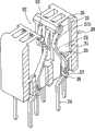
图1是本实用新型第一实施例的立体分解图。 Fig. 1 is a three-dimensional exploded view of the first embodiment of the utility model. the
图2是本实用新型第一实施例的一排端子展开平面图。 Fig. 2 is an expanded plan view of a row of terminals in the first embodiment of the present invention. the
图3是本实用新型第一实施例的立体组合图。 Fig. 3 is a three-dimensional assembled view of the first embodiment of the utility model. the
图4是本实用新型第一实施例的组合剖面图。 Fig. 4 is a combined sectional view of the first embodiment of the utility model. the
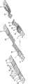
图5是本实用新型第一实施例的端子冲压制造流程示意图。 Fig. 5 is a schematic diagram of the terminal stamping manufacturing process of the first embodiment of the present invention. the
图6是本实用新型第一实施例的端子冲压制造示意图。 Fig. 6 is a schematic diagram of terminal stamping manufacturing in the first embodiment of the present invention. the
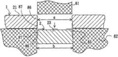
图7是本实用新型第一实施例的二排端子的延伸部的切断面示意图。 Fig. 7 is a cut-away schematic view of the extension part of the second row of terminals in the first embodiment of the present invention. the
图8是本实用新型第一实施例的第一排端子的其中一端子成反面反向接合于两端子之间的切断面接合状态示意图。 FIG. 8 is a schematic diagram of a cross-sectional joint state in which one terminal of the first row of terminals is reversely joined between the two terminals in the first embodiment of the present invention. the
图9是本实用新型第一实施例的第一排端子的其中一端子成正面反向接合于两端子之间的切断面接合状态示意图。 FIG. 9 is a schematic diagram of a cross-sectional joint state in which one terminal of the first row of terminals is joined between the two terminals in a front-to-back direction according to the first embodiment of the present invention. the
图10是本实用新型第二实施例的立体组合图。 Fig. 10 is a three-dimensional combined view of the second embodiment of the present invention. the
图11是本实用新型第三实施例的端子立体图。 Fig. 11 is a perspective view of a terminal of the third embodiment of the present invention. the
图12是本实用新型第三实施例的端子展开平面图。 Fig. 12 is a terminal development plan view of the third embodiment of the present invention. the
图13是本实用新型第三实施例的端子冲压制造流程示意图。 Fig. 13 is a schematic diagram of the terminal stamping manufacturing process of the third embodiment of the present invention. the
图14是本实用新型第四实施例的端子展开平面图。 Fig. 14 is a terminal development plan view of the fourth embodiment of the present invention. the
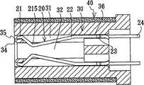
图15是本实用新型第五实施例的剖面侧视图。 Fig. 15 is a sectional side view of the fifth embodiment of the present utility model. the
图16是本实用新型第五实施例的剖面立体图。 Fig. 16 is a cross-sectional perspective view of the fifth embodiment of the present utility model. the
图17是本实用新型第五实施例的端子冲压制造流程示意图。 Fig. 17 is a schematic diagram of the terminal stamping manufacturing process of the fifth embodiment of the present invention. the
图18是本实用新型第六实施例的正面立体图。 Fig. 18 is a front perspective view of the sixth embodiment of the present invention. the
图19是本实用新型第六实施例的一排端子立体图。 Fig. 19 is a perspective view of a row of terminals of the sixth embodiment of the present invention. the
图20是本实用新型第六实施例的反面立体图。 Fig. 20 is a reverse perspective view of the sixth embodiment of the present invention. the
图21是本实用新型第七实施例的立体分解图。 Fig. 21 is an exploded perspective view of the seventh embodiment of the present invention. the
图22是本实用新型第七实施例的一排端子展开平面图。 Fig. 22 is an expanded plan view of a row of terminals of the seventh embodiment of the present invention. the
图23是本实用新型第七实施例的立体组合图。 Fig. 23 is a three-dimensional assembled view of the seventh embodiment of the present utility model. the
图24是本实用新型第七实施例的组合剖面图。 Fig. 24 is a combined sectional view of the seventh embodiment of the present utility model. the
图25是本实用新型第七实施例的端子冲压制造流程示意图。 Fig. 25 is a schematic diagram of the terminal stamping manufacturing process of the seventh embodiment of the present invention. the
图26是本实用新型第八实施例的端子展开平面图。 Fig. 26 is a terminal development plan view of the eighth embodiment of the present utility model. the
图27是本实用新型第九实施例的剖面侧视图。 Fig. 27 is a sectional side view of the ninth embodiment of the present invention. the
图28是本实用新型第九实施例的剖面立体图。 Fig. 28 is a cross-sectional perspective view of the ninth embodiment of the present invention. the
图29是本实用新型第九实施例的端子冲压制造流程示意图。 Fig. 29 is a schematic diagram of the terminal stamping manufacturing process of the ninth embodiment of the present invention. the
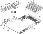
图30是本实用新型第十实施例的正面立体图。 Fig. 30 is a front perspective view of the tenth embodiment of the present utility model. the
图31是本实用新型第十实施例的一排端子立体图。 Fig. 31 is a perspective view of a row of terminals in the tenth embodiment of the present invention. the
图32是本实用新型第十实施例的反面立体图。 Fig. 32 is a reverse perspective view of the tenth embodiment of the present utility model. the
图33是本实用新型第十一实施例的立体分解图。 Fig. 33 is a three-dimensional exploded view of the eleventh embodiment of the present invention. the
图34是本实用新型第十一实施例的端子与塑胶座体立体分解图。 Fig. 34 is a three-dimensional exploded view of the terminal and the plastic seat of the eleventh embodiment of the present invention. the
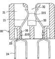
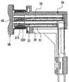
图35是本实用新型第十一实施例的剖面图。 Fig. 35 is a sectional view of the eleventh embodiment of the present utility model. the
图36是本实用新型第十一实施例的使用状态立体图。 Fig. 36 is a perspective view of the eleventh embodiment of the utility model in use. the
图37是本实用新型第十一实施例的二排端子对接立体图。 Fig. 37 is a perspective view of two rows of terminals butt joint in the eleventh embodiment of the present invention. the
图38是本实用新型第十一实施例的二排端子对接的展开平面图。 Fig. 38 is an expanded plan view of the butt joint of two rows of terminals in the eleventh embodiment of the present invention. the
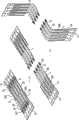
图39是本实用新型第十二实施例的二排端子立体分解图。 Fig. 39 is a three-dimensional exploded view of the second row of terminals of the twelfth embodiment of the present invention. the
图40是本实用新型第十二实施例的二排端子对接立体图。 Fig. 40 is a perspective view of the butt joint of two rows of terminals in the twelfth embodiment of the present invention. the
图41是本实用新型第十三实施例的二排端子立体分解图。 Fig. 41 is a three-dimensional exploded view of the second row of terminals in the thirteenth embodiment of the present invention. the
图42是本实用新型第十三实施例的二排端子对接立体图。 Fig. 42 is a perspective view of the butt joint of two rows of terminals in the thirteenth embodiment of the present invention. the
图43是本实用新型第十四实施例的剖面侧视图。 Fig. 43 is a sectional side view of the fourteenth embodiment of the present utility model. the
图44是本实用新型第十四实施例的塑胶座体的后视图。 Fig. 44 is a rear view of the plastic base of the fourteenth embodiment of the present invention. the
图45是本实用新型第十四实施例的使用状态图。 Fig. 45 is a diagram of the use state of the fourteenth embodiment of the utility model. the
图46是本实用新型第十四实施例的端子冲压制造流程示意图。 Fig. 46 is a schematic diagram of the terminal stamping manufacturing process of the fourteenth embodiment of the present invention. the
图47是本实用新型第十五实施例的端子冲压制造流程示意图。 Fig. 47 is a schematic diagram of the terminal stamping manufacturing process of the fifteenth embodiment of the present invention. the
图48是本实用新型第十六实施例的端子冲压制造流程示意图。 Fig. 48 is a schematic diagram of the terminal stamping manufacturing process of the sixteenth embodiment of the present invention. the
图49是本实用新型第十七实施例的立体分解图。 Fig. 49 is an exploded perspective view of the seventeenth embodiment of the present utility model. the
图50是本实用新型第十七实施例的剖面侧视图。 Fig. 50 is a sectional side view of the seventeenth embodiment of the present utility model. the
图51是本实用新型第十七实施例的端子冲压制造流程示意图。 Fig. 51 is a schematic diagram of the terminal stamping manufacturing process of the seventeenth embodiment of the present invention. the
图52是本实用新型第十八实施例的端子冲压制造流程示意图。 Fig. 52 is a schematic diagram of the terminal stamping manufacturing process of the eighteenth embodiment of the present invention. the
料带10 端子20 弹动部21 延伸部22 固定部23 接脚部24 切痕25 延伸部第一段26 延伸部第二段27 固定部第一段28 固定部第二段29
倒刺210 弹动部第一段211 弹动部第二段212 凹部213 接点215 连接凸部217 倒刺218 凹部219
辅助力臂220 第一端221 第二端222 连接片225 间隙226
塑胶座体30 端子槽31 连接槽32 开口33 导入斜面34 抵靠面35 卡槽36 后盖38 抵缘39凸部310 插孔312 金属外壳40 金属上盖45 顶面46 第一侧面47 第一侧面48
塑胶内座50 凸缘51 放置区52 端子槽53 Plastic
第一壁54 第二壁55 锡球槽56 锡球57
通道58 金属上盖60 顶面61 侧面62
透空区63 凸片64 枢接部65
公接头68 端子69
摇杆70 第一杆71 第二杆72 凸杆73
手把74 上模81 下模82 冲孔83 光滑面86 毛边87 金属外座90 底面91 侧面92
透空区93 第一枢接部94 第二枢接部95。 The
第一排端子1 第二排端子2 The first row of
【具体实施方式】【Detailed ways】
请参阅图1、图2、图3及图4,本实施例包括有:一塑胶座体30及二排端子20,其中: Please refer to Fig. 1, Fig. 2, Fig. 3 and Fig. 4, this embodiment includes: a
该塑胶座体30呈纵长条形状,其设有二排间隔排列的端子槽31,该两排端子槽31之间形成一纵长条形状的连接槽32,该端子槽31设有一开口33与该连接槽32相通,该连接槽32的开口朝上且上端设有导入斜面34,该端子槽31在开口33上端设有一抵靠面35且下段设有一卡槽36。 The
该二排端子20设于该塑胶座体30的二排端子槽31,每一排端子20 是连接一料带10,其为一金属片对撕冲压所形成相同二排端子的其中一排端子,该一排端子20组装于一排端子槽31后再将该料带10折断分离,该端子20由一端至另一端设有一弹动部21、一延伸部22、一固定部23及一接脚部24;该弹动部21设有第一、二端,该延伸部22设有第一、二端,该固定部23设有第一、二端,该弹动部21的第一端为端子的尾端,该弹动部的第二端连该接延伸部22第一端,该延伸部22第二端连接该固定部23的第一端,该固定部23的第二端连接该接脚24及该料带10且该处设有易于折断的切痕25,该固定部23宽度较该延伸部22宽度为宽借以与端子槽31的卡槽36卡定,该固定部23由第一端至第二端设成不同宽度的固定部第一段28和固定部第二段29,固定部第二段宽度A较固定部第一段宽度B为宽且两者间设有宽度更为凸出的倒刺210;该延伸部22宽度较该弹动部21宽度为宽,该延伸部22为一弯折的弹臂且由第一端至第二端设成等长的延伸部第一段26及延伸部第二段27,延伸部第二段宽度C较延伸部第一段宽度D为宽,该延伸部第一段26设有一凸出的接点215,该接点215由开口33伸出至该连接槽32;该弹动部21尾端弹性抵靠该抵靠面35,该弹动部21由第一端至第二端设成不同宽度的弹动部第一段211和弹动部第二段212,弹动部第二段宽度E较弹动部第一段宽度F为宽且两者间设有宽度更小的凹部213,该接脚部24伸出该塑胶座体30下端。 The two rows of
本实施例的特点在于该每一排端子是为一金属片对撕冲压所形成相同二排端子的其中一排,该二排端子的每一端子具有一对撕冲切部位相互无缝对接,该一排端子展开成平面时,其中一端子反向且反面接合于二相邻端子之间时,该一端子的对撕冲切部位与二相邻端子的对撕冲切部位无缝接合,本实施例的对撕冲切部位为弹动部21、延伸部22及固定部23。 The feature of this embodiment is that each row of terminals is one row of the same two rows of terminals formed by punching a pair of metal sheets. Each terminal of the two rows of terminals has a pair of tearing and punching parts that are seamlessly connected to each other. When the row of terminals is unfolded into a plane, when one of the terminals is reversed and the opposite side is joined between two adjacent terminals, the halves of the one terminal are seamlessly joined with the halves of the two adjacent terminals, In this embodiment, the parts for tearing and punching are the
该两相邻端子的弹动部21由第一端至第二端依序的间距等于该固定部23由第二端至第一端依序的宽度,且该两相邻端子的延伸部由第一端至第二端依序的间距等于该延伸部由第二端至第一端依序的宽度,该一排端子展开成平面时,该其中一端子的固定部23的形状可反向且反面无缝隙接合于两相邻端子的弹动部21间隔区域,该延伸部22的形状可反向且反面无缝隙接合于两相邻端子的延伸部22间隔区域,亦即两相邻端子的延伸部22间隔区域等于该延伸部22的面积。 The distance between the
该两相邻端子的弹动部第一段的间距X等于该固定部第二段宽度A,该 两相邻端子的弹动部第二段的间距Y等于该固定部第一段宽度B,该两相邻端子的延伸部第一段的间距Z等于该延伸部第二段宽度C,该延伸部第一段26的长度和该延伸部第二段27的长度相同,该弹动部第二段212的长度和固定部第一段28的长度相同,弹动部第一段宽度F+固定部第二段宽度A=延伸部第一段宽度D+延伸部第二段宽度C=弹动部第二段宽度E+固定部第一段宽度B;该一排端子展开成平面时,该固定部23的形状可无缝隙接合于两相邻端子的弹动部21间隔区域,即该固定部第一段28无缝隙靠合该两相邻端子的弹动部第二段212,该固定部第二段29无缝隙靠合该两相邻端子的弹动部第一段211,该倒刺210可无缝隙接合该两相邻端子的凹部213,另外,该两相邻端子的延伸部22间隔区域等于该延伸部22的面积。 The spacing X of the first segment of the elastic part of the two adjacent terminals is equal to the width A of the second segment of the fixed part, and the spacing Y of the second segment of the elastic part of the two adjacent terminals is equal to the width B of the first segment of the fixed part, The distance Z between the first section of the extension part of the two adjacent terminals is equal to the width C of the second section of the extension part, the length of the first section 26 of the extension part is the same as the length of the second section 27 of the extension part, and the second section of the elastic part The length of the second section 212 is the same as the length of the first section 28 of the fixed part, the first section width F of the elastic section + the second section width A of the fixed section = the first section width D of the extension section + the second section width C of the extension section = the elastic section The second segment width E+the first segment width B of the fixed part; when the row of terminals is unfolded into a plane, the shape of the fixed part 23 can be seamlessly joined to the interval area of the elastic part 21 of two adjacent terminals, that is, the second segment of the fixed part A section 28 is seamlessly attached to the second section 212 of the elastic part of the two adjacent terminals, and the second section 29 of the fixed section is seamlessly attached to the first section 211 of the elastic section of the two adjacent terminals. The
借由以上构造,端子在冲压制造上如图5所示,二排间隔排列相连接的端子可由一片金属片完全对接排列冲压,即第一排端子1的各端子20的固定部23恰可对接于第二排端子2的两相邻端子20的弹动部21之间,第一排端子1的各端子20的延伸部第二段27恰可对接于第二排端子2的两相邻端子20的延伸部第一段26之间,如此一金属片先完全无缝隙对撕成二排端子,再拉开后弯折弹动部21、延伸部22及接脚部24。 With the above structure, as shown in Figure 5 in the stamping and manufacturing of terminals, two rows of terminals connected at intervals can be stamped by a sheet of metal sheet that is completely butted and arranged, that is, the fixed
上述端子在制造上,二排端子对接冲压时除了相连的料带10外完全无废料形成,明显可节省材料,降低制造成本。 In the manufacture of the above-mentioned terminals, no waste material is formed except for the
请参阅图6及图7,本实用新型以一金属片对撕冲压成二排相同端子时,由于模具的上模81的宽度s必然较下模82的冲孔83的宽度b为小,由于第一排端子1的端子的弹动部21与第二排端子2的端子的固定部23无缝对撕,故冲压后第一排端子1的端子的弹动部21的切断面的上段形成光滑面86而下段形成毛边87,然而第二排端子2的端子的固定部23的切断面则是下段形成光滑面86而上段形成毛边87,光滑面86的宽度b较毛边87的宽度s稍大,第二排端子2的端子的固定部23接合于第一排端子2的端子的弹动部21的间隔区域时,两者接合处的切断面相互为毛边87接合光滑面86,故可成密合连接。 Please refer to Fig. 6 and Fig. 7, when the utility model stamps two rows of identical terminals with a metal sheet, the width s of the
如此冲压后第一排端子1的端子的弹动部21上段宽度与第二排端子2的端子的固定部23下段宽度均为b,而第一排端子1的端子的弹动部21下段宽度与第二排端子2的端子的弹动部上段宽度均为s,当第一排端子1的 端子20成反面时固定部的切断面即与第二排端子2的端子20的固定部的切断面相同。 After punching in this way, the width of the upper section of the
请参阅图8,第一排端子1其中一端子成反面反向接合于两端子之间时其固定部23’的切断面与该两相邻端子的弹动部21的切断面是相互为毛边87接合光滑面86,故可成密合连接。 Please refer to Fig. 8, when one terminal of the first row of
请参阅图9,第一排端子1其中一端子成同面反向接合于两端子之间时其固定部的切断面与该两相邻端子20的弹动部的切断面是相互为光滑面86接合光滑面86,故无法密合连接。 Please refer to FIG. 9 , when one terminal of the first row of
请参阅图10,为本实用新型第二实施例,其大致与第一实施例相同,其差异在于该端子20的延伸部第一段26的板面刺破冲压出一凸出的接点215。 Please refer to FIG. 10 , which is a second embodiment of the present invention, which is substantially the same as the first embodiment, and the difference is that a
请参阅图11及图12,为本实用新型第三实施例,其大致与第一实施例相同,其差异在于该端子20的延伸部22只有一个延伸部宽度H,该两相邻端子的延伸部的间距W等于该延伸部宽度H,该弹动部第二段212的长度和固定部第一段28的长度相同,弹动部第一段宽度F+固定部第二段宽度A=2倍延伸部宽度H=弹动部第二段宽度E+固定部第一段宽度B。 Please refer to Fig. 11 and Fig. 12, which is the third embodiment of the present utility model, which is roughly the same as the first embodiment, the difference is that the
本实施例端子在冲压制造上如图13所示,二排间隔排列相连接的端子可由一片金属片完全对接排列冲压,即第一排端子1的各端子20的固定部第二段29恰可对接于第二排端子2的两相邻端子20的弹动部第一段211之间,第一排端子1的各端子20的固定部第一段28恰可对接于第二排端子2的两相邻端子20的弹动部第二段212之间,第一排端子1的各端子20的延伸部22恰可对接于第二排端子2的两相邻端子20的延伸部22之间,如此一金属片先完全无缝隙对撕成二排端子,再拉开后弯折弹动部21、延伸部22及接脚部24。 As shown in Figure 13 in the stamping and manufacturing of terminals in this embodiment, two rows of terminals connected at intervals can be stamped by a piece of metal sheet that is completely butt-jointed and arranged, that is, the
请参阅图14,为本实用新型第四实施例,其大致与第一实施例相同,其差异在于该端子20的固定部23皆等宽只有一个宽度,而该弹动部21亦等宽只有一个宽度,而该延伸部22宽度由上而下渐宽,该两相邻端子的弹动部的间距P等于该固定部宽度Q,该端子20展开成平面时,该两相邻端子的延伸部22间隔区域等于该延伸部22的面积;借由以上构造,二排间隔排列相连接的端子可由一片金属片完全对接排列冲压。 Please refer to FIG. 14 , which is the fourth embodiment of the present utility model, which is roughly the same as the first embodiment. The difference is that the fixed
请参阅图15及图16,为本实用新型第五实施例,其是为一讯号线的 接头,其包括有:一塑胶座体30、二排端子20、及一金属外壳40,其中: See also Fig. 15 and Fig. 16, it is the fifth embodiment of the present utility model, and it is the joint of a signal line, and it comprises: A
该塑胶座体30设有二排间隔排列的端子槽31,该两排端子槽31呈一上一下排列并相面对,两排端子槽31之间形成一连接槽32,该端子槽31呈前后方向延伸且与该连接槽32相通,该连接槽32的前端为插入口且设有导入斜面34,该端子槽31后端设有一卡槽36且前端设有一抵靠面35。 The
该二排端子20设于该塑胶座体30的二排端子槽31,该端子20由一端至另一端设有一弹动部21、一延伸部22、一固定部23及一接脚部24,本实施例的端子20的构造大致与第一实施例相同,该延伸部22设有第一、二端,该延伸部22设有第一、二端,该固定部23设有第一、二端,该弹动部21的第一端为端子的尾端,该弹动部21的第二端连该接延伸部22第一端,该延伸部22第二端连接该固定部23的第一端,该固定部23的第二端连接该接脚24及该料带10且该处设有易于折断的切痕25,该固定部23宽度较该延伸部22宽度为宽借以与端子槽31的卡槽36卡定,该弹动部21弹性抵靠该塑胶座体的抵靠面35,本实施例与第一实施例的差异在于本实施例的端子20是呈横向延伸,该延伸部22由第一端至第二端呈同一宽度,该延伸部22横向延伸呈一弯折的弹臂且可上下弹动,其接近末端设有一凸出的接点215,该接点215伸出端子槽31至该连接槽32。 The two rows of
该金属外壳40包覆于该塑胶座体30外。 The
请参阅图17,是本实施例的冲压制造流程示意图,本实施例的端子20的构造大致与第一实施例相同,同样是该两相邻端子的弹动部21由第一端至第二端依序的间距等于该固定部23由第二端至第一端依序的宽度,且该两相邻端子的延伸部由第一端至第二端依序的间距等于该延伸部由第二端至第一端依序的宽度,该一排端子展开成平面时,其中一端子的固定部23的形状可反向且反面无缝隙接合于两相邻端子的弹动部21间隔区域,且该端子的延伸部22的形状可反向且反面无缝隙接合于两相邻端子的延伸部22间隔区域。 Please refer to Figure 17, which is a schematic diagram of the stamping manufacturing process of this embodiment. The structure of the terminal 20 of this embodiment is roughly the same as that of the first embodiment, and the
借由以上构造,端子在冲压制造上,二排间隔排列相连接的端子可由一片金属片对接排列冲压,由于第一排端子1的各端子20的延伸部22及固定部23分别无缝隙对接于第二排端子2的两相邻端子20的延伸部22及弹动部21之间,如此该金属片先对切成第一、二排端子1、2,再拉开后弯折延伸部22。 With the above structure, in the stamping manufacturing of terminals, two rows of terminals connected at intervals can be punched by a sheet of metal sheet butt-arranged, because the
请参阅图18、图19及图20,是为本实用新型第六实施例,其是为一Express card连接器,其包括有:一塑胶座体30、一排端子20、及一金属上盖45,其中: Please refer to Figure 18, Figure 19 and Figure 20, which are the sixth embodiment of the present utility model, which is an Express card connector, which includes: a
该塑胶座体30设有一排间隔排列的端子槽31及一连接槽32,该端子槽31呈前后方向延伸且与该连接槽32相通,该端子槽31前端亦有抵靠面35且后端设有卡槽。 The
该一排端子20设于该塑胶座体30的一排端子槽31,该端子20由一端至另一端设有一弹动部21、延伸部22、一固定部23及一接脚部24,该端子20构造大致与第五实施例相同,延伸部22亦为上下弹动型态,其差异在于本实施例的接脚部24是往下弯折后再形成一水平接脚。 The row of
该金属上盖45盖合于该塑胶座体30上方,其设有一顶面46及相对的第一、二侧面47、48。 The metal
本实施例的端子20的构造大致与第五实施例相同,同样是两相邻端子的弹动部21由第一端至第二端依序的间距等于该固定部23由第二端至第一端依序的宽度,且该两相邻端子的延伸部由第一端至第二端依序的间距等于该延伸部由第二端至第一端依序的宽度,该一排端子展开成平面时,其中一端子的固定部23的形状可反向且反面无缝隙接合于两相邻端子的弹动部21间隔区域,且该端子的延伸部22的形状可反向且反面无缝隙接合于两相邻端子的延伸部22间隔区域;借此,达到端子在冲压制造上节省材料。 The structure of the terminal 20 of this embodiment is roughly the same as that of the fifth embodiment, and the distance between the
请参阅图21、图22、图23及图24,是为本实用新型第七实施例,本实施例为一种记忆卡模组连接器,其包括有:一塑胶座体30及二排端子20,其中: Please refer to Fig. 21, Fig. 22, Fig. 23 and Fig. 24, which are the seventh embodiment of the present utility model. This embodiment is a memory card module connector, which includes: a
该塑胶座体30呈纵长条形状,其设有二排间隔排列的端子槽31,该两排端子槽31呈一间距并相面对且之间形成一纵长条形状的连接槽32,该端子槽31呈上下方向延伸且设有一开口33与该连接槽32相通,该连接槽32的开口朝上且上端设有导入斜面34,该端子槽31下段设有一卡槽36。 The
该二排端子20设于该塑胶座体30的二排端子槽31,每一排端子20是连接一料带10,该一排端子20组装于一排端子槽31后再将该料带10折断分离,该端子20由一端至另一端设有一弹动部21、一固定部23及一接脚部24;该固定部23下端连接该料带10且该处设有易于折断的切痕25, 该固定部23的宽度较该弹动部21的宽度和接脚部24的宽度为宽,该固定部23设有宽度更为凸出的倒刺210借以与端子槽31的卡槽36卡定;该弹动部21为单一宽度,其设有第一、二端221、222,第二端222与固定部连接,第一端221为开放端,该弹动部21上下延伸呈一弯折的弹臂且可侧向弹动,其接近末端设有一凸出的接点215,该接点215由开口33伸出端子槽31至该连接槽32,该接脚部24伸出该塑胶座体30下端。 The two rows of
本实施例的特点在于该每一排端子是为一金属片对撕冲压所形成相同二排端子的其中一排,该二排端子的每一端子具有一对撕冲切部位相互无缝对接,该一排端子展开成平面时,其中一端子反向且反面接合于二相邻端子之间时,该一端子的对撕冲切部位与二相邻端子的对撕冲切部位无缝接合,本实施例的对撕冲切部位为弹动部21。 The feature of this embodiment is that each row of terminals is one row of the same two rows of terminals formed by punching a pair of metal sheets. Each terminal of the two rows of terminals has a pair of tearing and punching parts that are seamlessly connected to each other. When the row of terminals is unfolded into a plane, when one of the terminals is reversed and the opposite side is joined between two adjacent terminals, the halves of the one terminal are seamlessly joined with the halves of the two adjacent terminals, In this embodiment, the part for tearing and punching is the
该同一排两相邻端子的弹动部21的间距A等于该弹动部21的宽度B,即该一排端子展开成平面时,其中一端子的弹动部21的形状可反向且反面无缝隙接合于两相邻端子的弹动部21间隔区域。 The distance A between the
借由以上构造,端子在冲压制造上如图25所示,二排间隔排列相连接的端子可由一片金属片对接排列冲压,由于第一排端子1的各端子20的弹动部21无缝隙对接于第二排端子2的两相邻端子20的弹动部21之间,如此该金属片先对切成第一、二排端子1、2,再拉开后弯折弹动部21及接脚部24。 With the above structure, as shown in Figure 25 in the stamping and manufacturing of terminals, two rows of terminals connected at intervals can be stamped by a sheet of metal butt-arranged, because the
上述端子在制造上,二排端子对接冲压时由于二排端子的延伸部是为无缝接合,而该弹动部21的长度占整体端子很大比率,故在制造上明显可节省材料,降低制造成本。 In the manufacture of the above-mentioned terminals, when the two rows of terminals are butt-jointed and punched, because the extension parts of the two rows of terminals are seamlessly joined, and the length of the
二排端子的固定部23虽没有相互对接,由于固定部23宽度甚宽,所以打掉的废料亦很少了,如图2的斜线部份即为两相邻端子的固定部间隔所打掉的废料。 Although the fixing
请参阅图26,是为本实用新型第八实施例,其大致与第七实施例相同,其差异在于本实施例的端子20的弹动部21由第一端221至第二端222渐宽,该同一排两相邻端子20的弹动部21由第一端221至第二端222依序的间距C等于该弹动部21由第二端222至第一端221依序的宽度D,即该一排端子展开成平面时,其中一端子的弹动部21的形状可反向且反面无缝隙接合于两相邻端子的弹动部21间隔区域。 Please refer to FIG. 26 , which is the eighth embodiment of the present utility model, which is roughly the same as the seventh embodiment, the difference being that the
请参阅图27及图28,是为本实用新型第九实施例,其是为一讯号线的接头,其包括有:一塑胶座体30、二排端子20、及一金属外壳40,其中: Please refer to Fig. 27 and Fig. 28, which are the ninth embodiment of the present utility model, which is a connector for a signal line, which includes: a
该塑胶座体30设有二排间隔排列的端子槽31,该两排端子槽31呈一上一下排列并相面对,两排端子槽31之间形成一连接槽32,该端子槽31呈前后方向延伸且与该连接槽32相通,该连接槽32的前端为插入口且设有导入斜面34,该端子槽31后端设有一卡槽36。 The
该二排端子20设于该塑胶座体30的二排端子槽31,该端子20由一端至另一端设有一弹动部21、一固定部23及一接脚部24,该固定部23的宽度较该弹动部21的宽度和接脚部24的宽度为宽借以与端子槽31的卡槽36卡定,该弹动部21横向延伸呈一弯折的弹臂且可上下弹动,其接近末端设有一凸出的接点215,该接点215伸出端子槽31至该连接槽32,该接脚部24伸出该塑胶座体30外。 The two rows of
该金属外壳40包覆于该塑胶座体30外。 The
请参阅图29,是本实施例的冲压制造流程示意图,本实施例的端子20的构造大致与第七实施例相同,同样是同一排两相邻端子的弹动部21的间距A等于该弹动部21的宽度B,即该一排端子展开成平面时,该弹动部21的形状可反向无缝隙接合于两相邻端子的弹动部21间隔区域,借由以上构造,端子在冲压制造上,二排间隔排列相连接的端子可由一片金属片对接排列冲压,由于第一排端子1的各端子20的弹动部21无缝隙对接于第二排端子2的两相邻端子20的弹动部21之间,如此该金属片先对切成第一、二排端子1、2,再拉开后弯折弹动部21。 Please refer to FIG. 29, which is a schematic diagram of the stamping manufacturing process of this embodiment. The structure of the terminal 20 of this embodiment is roughly the same as that of the seventh embodiment. Also, the distance A between the
请参阅图30、图31及图32,是为本实用新型第十实施例,其是为一Express card连接器,其包括有:一塑胶座体30、一排端子20、及一金属上盖45,其中: Please refer to Figure 30, Figure 31 and Figure 32, which are the tenth embodiment of the present utility model, which is an Express card connector, which includes: a
该塑胶座体30设有一排间隔排列的端子槽31及一连接槽32,该端子槽31呈前后方向延伸且与该连接槽32相通。 The
该一排端子20设于该塑胶座体30的一排端子槽31,该端子20由一端至另一端设有一弹动部21、一固定部23及一接脚部24,该固定部23的宽度较该弹动部21的宽度和接脚部24的宽度为宽借以与端子槽31的卡槽卡定,该弹动部21横向延伸呈一弯折的弹臂且可上下弹动,其接近末端设有一凸出的接点215,该接点215伸出端子槽31至该连接槽32,该接脚部 24伸出该塑胶座体30下端。 The row of
该金属上盖45盖合于该塑胶座体30上方,其设有一顶面46及相对的第一、二侧面47、48。 The metal
本实施例的端子20的构造大致与第九实施例相同,同样是同一排两相邻端子的弹动部21的间距A等于该弹动部21的宽度B,即该一排端子展开成平面时,其中一端子的弹动部21的形状可反向且反面无缝隙接合于两相邻端子的弹动部21间隔区域,借此,达到端子在冲压制造上节省材料。 The structure of the terminal 20 of this embodiment is roughly the same as that of the ninth embodiment. Also, the distance A between the
请参阅图33、图34、图35及图36,是为本实用新型第十一实施例,其是为一晶片连接器,其包括有:一金属外座90、一塑胶内座50、一金属上盖60、一摇杆70、及多排端子20,其中: Please refer to Figure 33, Figure 34, Figure 35 and Figure 36, which are the eleventh embodiment of the present utility model, which is a chip connector, which includes: a metal
该金属外座90设有一底面91及向上的两侧面92,该底面91的中央形成一透空区93,其前端两侧各设有一第一枢接部94,而后端两侧各设有一第二枢接部95。 The metal
该塑胶内座50设于该金属外座90上,其上周缘设有向上的凸缘51而围成一放置一晶片的放置区52,该放置区52间隔排列设有多排端子槽53,该多排端子槽53对应该透空区93,端子槽53设有与前、后排端子槽相隔的第一壁54及第二壁55,端子槽53下方对应设有一锡球槽56,该锡球槽56设有一锡球57,该端子槽53与锡球槽56设有通道58相通。 The plastic
该金属上盖60是设有一顶面61及向下的两侧面62,该顶面61中间设有一透空区63,其前端设有一凸片64,其后端两侧各设有一呈弯弧状的枢接部65。 The metal
该摇杆70设有相互呈垂直的第一杆71及第二杆72,该第二杆72枢接于金属外座90前端的第一枢接部94且中段弯曲形成一凸杆73,该第一杆71外端弯曲形成一手把74,当第一杆71往后摇动时,该凸杆73可压制该金属上盖60的凸片64而使该金属上盖60压住该晶片37。 The
该多排端子20设于该塑胶座体50的多排端子槽53,每一排端子20是连接一料带10,该一排端子20组装于一排端子槽53后再将该料带10分离,该端子20由一端至另一端设有一弹动部21、一固定部23、及一接脚部24,该固定部23较该弹动部21及接脚部24为宽借以定位于端子槽的第一壁54,该固定部23下端连接该接脚部24,固定部23上端中间连接该弹动部21且上端两侧各设有一连接凸部217与该料带10相连,该连接凸部217与该料带10相 连处设有切痕25,借以易于折断而使端子20与料带10分离,该弹动部21为一弯折的弹臂,该弹动部21先延伸至第二壁55再回转向固定部23延伸并逾过该第一壁54至前排的端子槽53上方,该弹动部21接近末端设有一接点28,该接点28为端子的最高点且凸出该端子槽53至该放置区52,当该接点28受力时弹动部21可上下弹动,该接脚部24是由该通道58伸至该锡球槽56,该接脚部24弯折挡扣该锡球57一侧。 The multiple rows of
本实施例的特点在于该每一排端子是为一金属片对撕冲压所形成相同二排端子的其中一排,该二排端子的每一端子具有一对撕冲切部位相互无缝对接,该一排端子展开成平面时,其中一端子反向且反面接合于二相邻端子之间时,该一端子的对撕冲切部位与二相邻端子的对撕冲切部位无缝接合,本实施例的对撕冲切部位为固定部23和接脚部24。 The feature of this embodiment is that each row of terminals is one row of the same two rows of terminals formed by punching a pair of metal sheets. Each terminal of the two rows of terminals has a pair of tearing and punching parts that are seamlessly connected to each other. When the row of terminals is unfolded into a plane, when one of the terminals is reversed and the opposite side is joined between two adjacent terminals, the halves of the one terminal are seamlessly joined with the halves of the two adjacent terminals, In this embodiment, the parts for tearing and punching are the fixing
该相邻端子20的接脚部间距X等于该固定部23宽度Y,该一端子的固定部23的形状可反向且反面接合于二相邻端子的接脚部24间隔区域且无缝隙靠合该二相邻端子的接脚部24。 The distance X between the pins of the
借由以上构造,由于相邻端子20的接脚部间距X等于该固定部23的宽度Y,请参阅图37及图38,在冲压制造上,二排间隔排列相连接的端子可对接排列由同一金属片冲压,即第一排端子1的各端子20的固定部23恰可对接于第二排端子2的相邻端子20的接脚部24间,如此一金属片冲压出二排端子,除了相连的料带外完全无废料形成,明显可节省材料,降低制造成本。 With the above structure, since the pitch X between
请参阅图39及图40,是为本实用新型第十二实施例,本实施例大致与第十一实施例相同,其差别在于本实施例端子20的弹动部21是连接于该固定部23上端一侧,该固定部23上端另一侧则设有一连接凸部217与该料带10相连。 Please refer to Figure 39 and Figure 40, which are the twelfth embodiment of the present utility model, this embodiment is roughly the same as the eleventh embodiment, the difference is that the
请参阅图41及图42,是为本实用新型第十三实施例,本实施例大致与第十一实施例相同,其差别在于本实施例端子20的固定部23上端一侧设有一连接凸部217与该料带10相连,该弹动部21是连接于该连接凸部217一侧且转折与连接凸部217成90度夹角,另外,该端子20的固定部23设有宽度更为凸出的倒刺218,该接脚部23设有宽度更小的凹部219,该倒刺218可无缝隙接合该凹部219。 Please refer to Fig. 41 and Fig. 42, which are the thirteenth embodiment of the present utility model. This embodiment is roughly the same as the eleventh embodiment.
请参阅图43及图44,是为本实用新型第十四实施例,其是为一D-SUB 电连接器,其包括有:一塑胶座体30、二排端子20、及一金属外壳40,其中: Please refer to Figure 43 and Figure 44, which are the fourteenth embodiment of the present utility model, which is a D-SUB electrical connector, which includes: a
该塑胶座体30是为架高型式者,其内设有多个端子槽31及多个连接槽32,该多数的端子槽31及多个连接槽32由上而下呈二排,其前端设有一凸部310,该凸部310前端设有多个插孔312对应该多个连接槽32,及设有凹陷的卡槽36,另该每一端子槽31上端设有宽度较小的开口33与该连接槽32相通,使该开口的二侧形成抵缘39及设有凹陷的卡槽36,另外,设有一后盖38盖于该塑胶座体30后方。 The
该二排端子20对应组装于该塑胶座体的二排端子槽31,该每一端子20由一端至另一端依序设有一弹动部21、一固定部23及一接脚部24,该弹动部21为单一力臂且板面呈水平并可弹动,该弹动部21接近末端的板面刺破冲压凸出一宽度较窄的接点215,该弹动部21末端反折设有一与该接点215反向凸出的辅助力臂220,该弹动部21弹性抵于该抵缘39,该接点215凸出至该连接槽32,该辅助力臂220抵于该端子槽31的一壁面,该固定部23设有第一、二端,第一端连接弹动部21,第二端连接接脚部24, The two rows of
该固定部23与该卡槽36卡定,该固定部23弯折成二垂直板面,纵向板面向下延伸并连接该接脚部24,该接脚部24的板面弯折使截面呈ㄇ形状并伸出该塑胶座体。 The fixing
该金属外壳40套合于塑胶座体30前端,其包覆该凸部310的周边而使凸部前面的插孔312露出。 The
请参阅图45,借由以上构造,当公接头68插入时,公接头68的二排端子69插入该二排连接槽32,该端子69挤压该接点215,使该弹动部21向下弹动,同时该辅助力臂220亦被压缩,如此借由该弹动部21的弹性及辅助力臂220的弹性而能提供该公接头68的端子69与接点215良好的弹性接触。 Please refer to FIG. 45 , with the above structure, when the
本实施例的特点在于该每一排端子20是为一金属片对撕冲压所形成相同二排端子的其中一排,该二排端子的每一端子20具有一对撕冲切部位相互无缝对接,该一排端子20展开成平面时,其中一端子20反向且反面接合于二相邻端子之间时,该一端子的对撕冲切部位与二相邻端子的对撕冲切部位无缝接合,本实施例的对撕冲切部位为固定部23,一排端子中二相邻端子的固定部23由第一端至第二端依序的间距等于其中一端子的固定部23由第二端至第一端依序的宽度,本实施例的固定部23由第一端至第二端 为同一宽度,该一排端子20展开成平面时,其中一端子20反向且反面接合于二相邻端子之间时,该一端子的固定部23与二相邻端子的固定部23无缝接合。 The feature of this embodiment is that each row of
本实施例的端子20在冲压制造上如图46所示,二排间隔排列相连接的端子是由一片金属片对接排列冲压而成,由于第一排端子1的各端子20的固定部23无缝隙对接于第二排端子2的两相邻端子20的固定部23之间,如此该金属片先对撕成第一、二排端子1、2,再拉开后弯折固定部23。 The terminal 20 of this embodiment is stamped and manufactured as shown in FIG. 46. Two rows of terminals arranged at intervals and connected are stamped and formed by a sheet of metal butt-jointed arrangement. Since the fixing
请参阅图47,是为本实用新型第十五实施例,其大致与第十四实施例相同,其差异在于本实施例的塑胶座体较第十四实施例为低,故固定部23及接脚部24均较短,本实施例的对撕冲切部位亦为固定部23,该固定部23为均一宽度,该一排端子20展开成平面时,其中一端子20反向且反面接合于二相邻端子之间时,该一端子的固定部23与二相邻端子的固定部23无缝接合。本实施例端子20在冲压制造上,二排间隔排列相连接的端子是由一片金属片对接排列冲压而成,由于第一排端子1的各端子20的固定部23无缝隙对接于第二排端子2的两相邻端子20的固定部23之间,如此该金属片先对撕成第一、二排端子1、2,再拉开后弯折固定部23。 Please refer to Fig. 47, which is the fifteenth embodiment of the present utility model, which is roughly the same as the fourteenth embodiment. The
请参阅图48,是为本实用新型第十六实施例,其大致与第十五实施例相同,本实施例的一排端子20是连接一料带10,其为一金属片对撕冲压所形成相同二排端子的其中一排端子,每一端子20由一端至另一端设有一弹动部21、一固定部23、及一接脚部24;该弹动部21的板面冲压凸出一接点215,该接脚部24的两侧各无缝接合一连接片225,该二连接片225是一端连接料带,另一端连接于固定部23一端,并设有折痕以方便折断。 Please refer to Figure 48, which is the sixteenth embodiment of the present utility model, which is roughly the same as the fifteenth embodiment. A row of
本实施例特点同样在于该每一排端子20是为一金属片对撕冲压所形成相同二排端子的其中一排,该二排端子的每一端子20具有一对撕冲切部位相互无缝对接,该一排端子20展开成平面时,其中一端子20反向且反面接合于二相邻端子之间时,该一端子的对撕冲切部位与二相邻端子的对撕冲切部位无缝接合,本实施例的对撕冲切部位为弹动部21、固定部23和接脚部24两侧的连接片225,该一排端子20展开成平面时,其中一端子20反向且反面接合于二相邻端子之间时,该一端子的弹动部21及固定部23和二相邻端子的接脚部24两侧的连接片225无缝接合。 The feature of this embodiment is also that each row of
本实施例端子20在冲压制造上,二排间隔排列相连接的端子是由一片 金属片对接排列冲压而成,由于第一排端子1的各端子20的弹动部21和固定部23无缝隙对接于第二排端子2的两相邻端子20的接脚部24两侧的连接片225,如此该金属片先对撕成第一、二排端子1、2,再拉开后弯折固定部23。 In the stamping manufacturing of the
请参阅图49及图50,是为本实用新型第十七实施例,其是为一直立式D-SUB电连接器,其包括有:一塑胶座体30、三排端子20、及一金属外壳40,其中: Please refer to Figure 49 and Figure 50, which are the seventeenth embodiment of the present utility model, which is a vertical D-SUB electrical connector, which includes: a
该塑胶座体30是直立式者,其内设有多个端子槽31及多个连接槽32,该多数的端子槽31及多个连接槽32呈三排,其上端设有一凸部310,该凸部310前端设有多个插孔312对应该多个连接槽32,该每一端子槽31如同第十四实施例设有宽度较小的开口33与该连接槽32相通,该开口的二侧形成抵缘39。 The
该三排端子20对应组装于该塑胶座体的三排端子槽31,该每一端子20由一端至另一端依序设有一弹动部21、一延伸部22、一固定部23及一接脚部24,该弹动部21为单一力臂且板面呈纵向并可弹动,该弹动部21接近末端的板面刺破冲压凸出一宽度较窄的接点215,该弹动部21弹性抵于该抵缘39,该接点215凸出至该连接槽32,该固定部23及延伸部22与该端子槽31卡定,该接脚部24伸出该塑胶座体30。 The three rows of
该金属外壳40套合于塑胶座体30前端,其包覆该凸部310的周边而使凸部上面的插孔312露出。 The
请参阅图51,本实施例的一排端子是为一金属片对撕冲压所形成相同二排端子的其中一排端子,其包括有:一料带10及多个端子20,其中: Please refer to FIG. 51. The row of terminals in this embodiment is one of the same two rows of terminals formed by stamping a sheet of metal. It includes: a
该料带10,其上设有多个间隔排列的长形孔11。 The
该多个端子20呈间隔排列连接于该料带10,该弹动部21设有第一、二端,该延伸部22设有第一、二端,该固定部23设有第一、二端,该弹动部21的第一端为端子的尾端,该弹动部21的第二端连该接延伸部22第一端,该延伸部22第二端连接该固定部23的第一端,该固定部23的第二端连接该接脚24及该料带10,该固定部23宽度较弹动部21宽度为宽,本实施例的端子的弹动部21及固定部23由第一端至第二端呈同一宽度,而该延伸部22由第一端至第二端则呈凸凹间隔形状。 The plurality of
本实施例的端子20的构造大致与第一实施例相同,同样是该两相邻端 子的弹动部21由第一端至第二端依序的间距等于该固定部23由第二端至第一端依序的宽度,且该两相邻端子的延伸部由第一端至第二端依序的间距等于该延伸部由第二端至第一端依序的宽度,该一排端子展开成平面时,该固定部23的形状可反向且反面无缝隙接合于两相邻端子的弹动部21间隔区域,该延伸部22的形状可反向无缝隙接合于两相邻端子的延伸部22间隔区域。 The structure of the terminal 20 of this embodiment is roughly the same as that of the first embodiment, and the distance between the
借由以上构造,端子在冲压制造上,二排间隔排列相连接的端子可由一片金属片对接排列冲压,由于第一排端子1的各端子20的延伸部22及固定部23分别无缝隙对接于第二排端子2的两相邻端子20的延伸部22及弹动部21之间,如此该金属片先对撕成第一、二排端子1、2,再拉开后弯折冲压该弹动部21。 With the above structure, in the stamping manufacturing of terminals, two rows of terminals connected at intervals can be punched by a sheet of metal sheet butt-arranged, because the
请参阅图52,是为本实用新型第十八实施例,本实施例的端子20的构造大致与第十七实施例相同,其差异仅在于本实施例的第一排端子1的端子20的延伸部22与第一排端子2的端子20的延伸部22对接时形成部份间隙226。 Please refer to Figure 52, which is the eighteenth embodiment of the present utility model. The structure of the terminal 20 of this embodiment is roughly the same as that of the seventeenth embodiment. A partial gap 226 is formed when the
在较佳实施例的详细说明中所提出的具体的实施例仅为了易于说明本实用新型的技术内容,而并非将本实用新型狭义地限制于该实施例,在不超出本实用新型的精神及以下申请专利范围的情况,可作种种变化实施。 The specific embodiments proposed in the detailed description of the preferred embodiments are only for the ease of explaining the technical content of the present utility model, and are not limited to the present utility model in a narrow sense. The situation of following scope of application for a patent can be implemented in various changes. the
Claims (44)
Priority Applications (1)
| Application Number | Priority Date | Filing Date | Title |
|---|---|---|---|
| CN2009202914045UCN201663252U (en) | 2009-01-12 | 2009-12-14 | Electrical connector and its terminal structure |
Applications Claiming Priority (22)
| Application Number | Priority Date | Filing Date | Title |
|---|---|---|---|
| CN200920003111.2 | 2009-01-12 | ||
| CN200920003111 | 2009-01-12 | ||
| CN200920007459.9 | 2009-03-06 | ||
| CN200920007459 | 2009-03-06 | ||
| CN200920008311.7 | 2009-03-26 | ||
| CN200920008311 | 2009-03-26 | ||
| CN200920008967.9 | 2009-03-27 | ||
| CN200920008968 | 2009-03-27 | ||
| CN200920008967 | 2009-03-27 | ||
| CN200920008968.3 | 2009-03-27 | ||
| CN200920146790 | 2009-06-02 | ||
| CN200920146790.9 | 2009-06-02 | ||
| CN200920146791 | 2009-06-02 | ||
| CN200920146791.3 | 2009-06-02 | ||
| CN200920152427.8 | 2009-06-05 | ||
| CN200920152427 | 2009-06-05 | ||
| CN200920156921 | 2009-06-09 | ||
| CN200920156921.1 | 2009-06-09 | ||
| CN200920177768 | 2009-09-10 | ||
| CN200920177768.0 | 2009-09-10 | ||
| CN200920219524.4 | 2009-10-12 | ||
| CN2009202914045UCN201663252U (en) | 2009-01-12 | 2009-12-14 | Electrical connector and its terminal structure |
Publications (1)
| Publication Number | Publication Date |
|---|---|
| CN201663252Utrue CN201663252U (en) | 2010-12-01 |
Family
ID=43233673
Family Applications (2)
| Application Number | Title | Priority Date | Filing Date |
|---|---|---|---|
| CN2009202914045UExpired - Fee RelatedCN201663252U (en) | 2009-01-12 | 2009-12-14 | Electrical connector and its terminal structure |
| CN2009102583441APendingCN102025052A (en) | 2009-01-12 | 2009-12-14 | Electric connector and terminal structure thereof |
Family Applications After (1)
| Application Number | Title | Priority Date | Filing Date |
|---|---|---|---|
| CN2009102583441APendingCN102025052A (en) | 2009-01-12 | 2009-12-14 | Electric connector and terminal structure thereof |
Country Status (1)
| Country | Link |
|---|---|
| CN (2) | CN201663252U (en) |
Cited By (2)
| Publication number | Priority date | Publication date | Assignee | Title |
|---|---|---|---|---|
| CN111628312A (en)* | 2019-02-27 | 2020-09-04 | 住友电装株式会社 | Chain terminal and connector for substrate having terminal in chain terminal |
| USRE49287E1 (en) | 2009-04-15 | 2022-11-08 | Kiwi Connection, Llc | Socket structure with duplex electrical connection |
Families Citing this family (1)
| Publication number | Priority date | Publication date | Assignee | Title |
|---|---|---|---|---|
| CN108767521B (en)* | 2018-05-22 | 2024-07-02 | 深圳市深台帏翔电子有限公司 | Connector and terminal device |
- 2009
- 2009-12-14CNCN2009202914045Upatent/CN201663252U/ennot_activeExpired - Fee Related
- 2009-12-14CNCN2009102583441Apatent/CN102025052A/enactivePending
Cited By (4)
| Publication number | Priority date | Publication date | Assignee | Title |
|---|---|---|---|---|
| USRE49287E1 (en) | 2009-04-15 | 2022-11-08 | Kiwi Connection, Llc | Socket structure with duplex electrical connection |
| USRE50307E1 (en) | 2009-04-15 | 2025-02-18 | Kiwi Intellectual Assets Corporation | Socket structure with duplex electrical connection |
| CN111628312A (en)* | 2019-02-27 | 2020-09-04 | 住友电装株式会社 | Chain terminal and connector for substrate having terminal in chain terminal |
| CN111628312B (en)* | 2019-02-27 | 2022-05-17 | 住友电装株式会社 | Chain type terminal and connector for substrate with terminal in chain type terminal |
Also Published As
| Publication number | Publication date |
|---|---|
| CN102025052A (en) | 2011-04-20 |
Similar Documents
| Publication | Publication Date | Title |
|---|---|---|
| US20090275237A1 (en) | SIM Card Connector | |
| TW200531383A (en) | Electrical connector for memory modules | |
| CN201663252U (en) | Electrical connector and its terminal structure | |
| CN201167158Y (en) | Cross-arranged two-row continuous terminal structure | |
| CN201708327U (en) | electrical connector | |
| CN201549671U (en) | D-SUB electrical connector | |
| USD595651S1 (en) | Resilient microelectronic connector | |
| CN202906045U (en) | electrical connection socket | |
| CN201838763U (en) | Electrical connector and its terminal structure | |
| CN101197473A (en) | Terminal structure of electric connector | |
| CN101783448A (en) | Board-to-board electrical connector | |
| CN201515047U (en) | Shareable memory card socket | |
| CN201171095Y (en) | Board-to-Board Connector | |
| CN202067925U (en) | Smart card connector and terminal structure thereof | |
| CN201845913U (en) | Electric connector and pair of switch terminals thereof | |
| JP2009218174A (en) | Receptacle | |
| CN101227039A (en) | electrical connector | |
| CN201029113Y (en) | electrical connector | |
| CN201256229Y (en) | Radio frequency connector | |
| KR20110003909U (en) | Electrical connector and its terminal structure | |
| CN205282694U (en) | electrical connector | |
| TWD116895S1 (en) | Connector | |
| CN201503936U (en) | electrical connector | |
| CN222545853U (en) | A connecting mechanism, a swinging structure and a paper model | |
| CN201054411Y (en) | Terminal structure of electric connector |
Legal Events
| Date | Code | Title | Description |
|---|---|---|---|
| C14 | Grant of patent or utility model | ||
| GR01 | Patent grant | ||
| C17 | Cessation of patent right | ||
| CF01 | Termination of patent right due to non-payment of annual fee | Granted publication date:20101201 Termination date:20121214 |