CN201576123U - Corrugated tile concentrating device - Google Patents
Corrugated tile concentrating deviceDownload PDFInfo
- Publication number
- CN201576123U CN201576123UCN200920233387XUCN200920233387UCN201576123UCN 201576123 UCN201576123 UCN 201576123UCN 200920233387X UCN200920233387X UCN 200920233387XUCN 200920233387 UCN200920233387 UCN 200920233387UCN 201576123 UCN201576123 UCN 201576123U
- Authority
- CN
- China
- Prior art keywords
- corrugated tile
- light
- condensing unit
- beam condensing
- corrugated
- Prior art date
- Legal status (The legal status is an assumption and is not a legal conclusion. Google has not performed a legal analysis and makes no representation as to the accuracy of the status listed.)
- Expired - Fee Related
Links
- 239000000463materialSubstances0.000claimsdescription3
- 230000005540biological transmissionEffects0.000claims1
- 238000010248power generationMethods0.000abstractdescription8
- 230000003287optical effectEffects0.000abstractdescription3
- 238000006243chemical reactionMethods0.000abstractdescription2
- 238000000034methodMethods0.000description11
- 239000011521glassSubstances0.000description6
- 238000004512die castingMethods0.000description4
- VYPSYNLAJGMNEJ-UHFFFAOYSA-NSilicium dioxideChemical compoundO=[Si]=OVYPSYNLAJGMNEJ-UHFFFAOYSA-N0.000description3
- 238000010586diagramMethods0.000description3
- 238000000465mouldingMethods0.000description3
- 238000002834transmittanceMethods0.000description3
- 229910000838Al alloyInorganic materials0.000description2
- 238000005516engineering processMethods0.000description2
- 229920003229poly(methyl methacrylate)Polymers0.000description2
- 239000004926polymethyl methacrylateSubstances0.000description2
- 239000000741silica gelSubstances0.000description2
- 229910002027silica gelInorganic materials0.000description2
- XAGFODPZIPBFFR-UHFFFAOYSA-NaluminiumChemical compound[Al]XAGFODPZIPBFFR-UHFFFAOYSA-N0.000description1
- 229910052782aluminiumInorganic materials0.000description1
- 239000005388borosilicate glassSubstances0.000description1
- 238000001816coolingMethods0.000description1
- 230000000694effectsEffects0.000description1
- 239000005329float glassSubstances0.000description1
- 238000009434installationMethods0.000description1
- 238000012423maintenanceMethods0.000description1
Images


Classifications
- Y—GENERAL TAGGING OF NEW TECHNOLOGICAL DEVELOPMENTS; GENERAL TAGGING OF CROSS-SECTIONAL TECHNOLOGIES SPANNING OVER SEVERAL SECTIONS OF THE IPC; TECHNICAL SUBJECTS COVERED BY FORMER USPC CROSS-REFERENCE ART COLLECTIONS [XRACs] AND DIGESTS
- Y02—TECHNOLOGIES OR APPLICATIONS FOR MITIGATION OR ADAPTATION AGAINST CLIMATE CHANGE
- Y02B—CLIMATE CHANGE MITIGATION TECHNOLOGIES RELATED TO BUILDINGS, e.g. HOUSING, HOUSE APPLIANCES OR RELATED END-USER APPLICATIONS
- Y02B10/00—Integration of renewable energy sources in buildings
- Y02B10/10—Photovoltaic [PV]
- Y—GENERAL TAGGING OF NEW TECHNOLOGICAL DEVELOPMENTS; GENERAL TAGGING OF CROSS-SECTIONAL TECHNOLOGIES SPANNING OVER SEVERAL SECTIONS OF THE IPC; TECHNICAL SUBJECTS COVERED BY FORMER USPC CROSS-REFERENCE ART COLLECTIONS [XRACs] AND DIGESTS
- Y02—TECHNOLOGIES OR APPLICATIONS FOR MITIGATION OR ADAPTATION AGAINST CLIMATE CHANGE
- Y02E—REDUCTION OF GREENHOUSE GAS [GHG] EMISSIONS, RELATED TO ENERGY GENERATION, TRANSMISSION OR DISTRIBUTION
- Y02E10/00—Energy generation through renewable energy sources
- Y02E10/50—Photovoltaic [PV] energy
Landscapes
- Photovoltaic Devices (AREA)
- Optical Elements Other Than Lenses (AREA)
Abstract
Translated fromChinese
Description
Translated fromChinese所属技术领域Technical field
本实用新型涉及太阳能发电领域,具体是一种波形瓦聚光装置。The utility model relates to the field of solar power generation, in particular to a corrugated tile light concentrating device.
背景技术Background technique
太阳能光伏发电技术为未来解决能源问题提供广阔前景,但存在发电成本高,光电转换效率不高的问题。因此,降低成本和提高效率成为太阳能发电大规模应用的关键,太阳能聚光是降低太阳能光伏发电成本的有效途径。太阳光聚光一般采用菲涅耳透镜、槽形反射、抛物面反射等方式,但需安装太阳光跟踪器才能达到聚光效果。采用太阳光跟踪器,成本高,可靠性差,无法与建筑一体化相结合,不便于安装。取消太阳光跟踪器是目前太阳能发电领域迫切需要解决的技术问题。Solar photovoltaic power generation technology provides broad prospects for solving energy problems in the future, but there are problems of high power generation costs and low photoelectric conversion efficiency. Therefore, cost reduction and efficiency improvement have become the key to the large-scale application of solar power generation, and solar concentration is an effective way to reduce the cost of solar photovoltaic power generation. Concentrating sunlight generally adopts Fresnel lens, trough reflection, parabolic reflection and other methods, but it is necessary to install a solar tracker to achieve the concentrating effect. The use of solar trackers has high cost and poor reliability, and cannot be integrated with buildings, which is not easy to install. Canceling the solar tracker is an urgent technical problem in the field of solar power generation.
为了取消太阳光跟踪器,目前有采用球聚焦的方式,如专利申请号为20610076928.3公开的一种“太阳光集聚器”,专利号ZL200620005067.5公开的一种“万向聚光镜”,专利号ZL200820185105.9公开的一种“全方向太阳光聚光装置”。这些聚光方式能聚集太阳光,聚焦比高,但由于体积、重量较大,不方便安装,在太阳能发电领域无法大规模实用推广。In order to cancel the solar tracker, there is currently a spherical focusing method, such as a "sunlight concentrator" disclosed in patent application No. 20610076928.3, a "universal concentrator" disclosed in patent No. ZL200620005067.5, and patent No. ZL200820185105 .9 discloses a "omnidirectional sunlight concentrating device". These concentrating methods can gather sunlight and have a high focusing ratio, but due to their large size and weight, they are inconvenient to install and cannot be widely used in the field of solar power generation.
综上所述,现有聚光方式都能把太阳光聚焦于一点,聚焦点随着太阳光的移动而移动,普遍采用成本较高、性能不稳定、安装维护不便的太阳光跟踪器,不易与建筑相结合。To sum up, the existing concentrating methods can focus sunlight on one point, and the focus point moves with the movement of sunlight. It is not easy to use solar trackers with high cost, unstable performance, and inconvenient installation and maintenance. Combined with architecture.
本发明内容Contents of the invention
本实用新型的目的是为了克服现有技术中太阳光线聚焦于一点,聚光点随太阳光的移动而移动,需要安装太阳光跟踪器的缺点,提供一种波形瓦太阳光聚光装置,采用波形面集光,对称设计的透镜聚光,聚光槽反射聚光均光的聚光方式,使太阳光始终聚集于一固定带状平面上,省去太阳光跟踪器。The purpose of this utility model is to overcome the shortcomings of the prior art that the sun's rays are focused on one point, and the spot moves with the movement of the sun, and a sun tracker needs to be installed. The wave-shaped surface collects light, the symmetrically designed lens gathers light, and the light-gathering groove reflects and gathers light evenly, so that the sunlight is always concentrated on a fixed strip-shaped plane, eliminating the need for a solar tracker.
为了实现上述目的,本实用新型采用的技术方案是:波形瓦聚光装置包括波形瓦聚光透镜和聚光槽,技术特点在于所述波形瓦聚光透镜包括具有任意方向光线入射在同一波形面的入光面和若干个对称设计的等宽度柱面线形菲涅耳透镜组成的若干出光面,小棱镜的一棱角边垂直于波形面,另一棱角边与波形面形成棱角,不同入射高处小棱镜对光线是以最小偏向角向主光轴偏向的,大部分出射光线直接落在聚光槽下口固定平面上,部分出射光线经聚光槽的反光壁反射至聚光槽下口固定平面上,形成均匀的太阳光焦带。In order to achieve the above object, the technical solution adopted in the utility model is: the corrugated tile concentrating device includes a corrugated tile concentrating lens and a concentrating groove, and the technical feature is that the corrugated tile concentrating lens includes The light incident surface of the small prism and several light exit surfaces composed of several symmetrically designed equal-width cylindrical linear Fresnel lenses. One angular side of the small prism is perpendicular to the wave surface, and the other angular edge forms an angle with the wave surface. Different incident heights The small prism deflects the light to the main optical axis at the minimum deflection angle, most of the outgoing light falls directly on the fixed plane of the lower opening of the light-gathering groove, and part of the outgoing light is reflected by the reflective wall of the light-gathering groove to the lower mouth of the light-gathering groove and fixed On the plane, a uniform solar focal zone is formed.
所述的波形瓦聚光透镜为等于或小于半管形的对称设计等宽度柱面线形菲涅耳透镜,管口方向采用一维东西方向放置。The corrugated tile condenser lens is a symmetrically designed equal-width cylindrical linear Fresnel lens equal to or smaller than a half-tube shape, and the nozzle direction is placed in a one-dimensional east-west direction.
所述的波形瓦聚光透镜每个小棱镜的宽度为0.1-6mm。The width of each small prism of the corrugated tile condenser lens is 0.1-6mm.
所述的波形瓦聚光透镜每个小棱镜棱角小于60°。The prism angle of each small prism in the corrugated tile condenser lens is less than 60°.
所述聚光槽上、下口均为四边形,上口大下口小,侧面与底平面的夹角为60°,聚光槽下口连接太阳能电池片或太阳能电池组件。The upper and lower openings of the light-gathering groove are quadrangular, the upper mouth is larger and the lower mouth is smaller, and the angle between the side surface and the bottom plane is 60°, and the lower opening of the light-gathering groove is connected to solar cells or solar cell modules.
附图说明Description of drawings
图1为本实用新型结构示意图;Fig. 1 is a structural representation of the utility model;
图2为本实用新型波形瓦聚光透镜示意图;Fig. 2 is a schematic diagram of the utility model corrugated tile condenser lens;
图3为本实用新型截面示意图;Fig. 3 is a schematic cross-sectional view of the utility model;
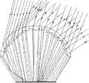
图4为中午太阳光入射波形瓦聚光透镜后的光折射反射示意图;Fig. 4 is the schematic diagram of light refraction and reflection after sunlight incident corrugated tile condenser lens at noon;
图5为上午或下午太阳光入射波形瓦聚光透镜后的光折射反射示意图;Fig. 5 is the schematic diagram of light refraction and reflection after sunlight incident corrugated tile condenser lens in the morning or afternoon;
附图中,波形瓦聚光透镜1,线形菲涅耳透镜2,平面镜反射聚光槽3,聚光槽下口固定平面4。In the accompanying drawings, a corrugated
具体实施方式Detailed ways
结合附图和具体实施方式对本实用新型作详细说明。The utility model is described in detail in conjunction with the accompanying drawings and specific embodiments.
图1、2、3中,一种波形瓦聚光装置,主要有波形瓦聚光透镜1和反光镜聚光槽3组成,波形瓦聚光透镜1为半管或小于半管形,波形瓦聚光透镜1包括具有任意方向光线入射在同一波形面的入光面和若干个对称设计的等宽度柱面线形菲涅耳透镜2组成的若干出光面,小棱镜的一棱角边垂直于波形面,另一棱角边与波形面形成小于60°棱角,不同入射高处小棱镜对光线是以最小偏向角向主光轴偏向的,大部分出射光线直接落在聚光槽下口固定平面4上,部分出射光线经聚光槽的反光壁反射至聚光槽下口固定平面4上,形成均匀的太阳光焦带。聚光槽采用玻璃镀银镜面或铝反光膜,聚光槽上、下口均为四边形,上大下小,侧面与底平面的夹角为60°,聚光槽下口连接太阳能电池片或太阳能电池组件且聚光倍数随距离调整可控。Among Figures 1, 2, and 3, a corrugated tile concentrating device mainly consists of a corrugated
图4、5所示中,本实用新型波形瓦聚光透镜为半管或小于半管形,管口方向采用一维东西方向放置,将早中晚入射的太阳光经集光、折射聚光、反射聚光均光后,在聚光槽下口固定平面上形成均匀的太阳光焦带。As shown in Figures 4 and 5, the corrugated tile concentrating lens of the utility model is half-pipe or less than half-pipe, and the direction of the nozzle is placed in a one-dimensional east-west direction, and the sunlight incident in the morning, middle and evening is collected, refracted and concentrated 1. After reflecting and concentrating light uniformly, a uniform sunlight focal zone is formed on the fixed plane at the lower opening of the light concentrating groove.
本实用新型波形瓦聚光透镜选用折射率为1-5的材料:平板高透光率单面带减反射面超白浮法玻璃、高透光率石英玻璃、高透光率高硼硅玻璃、耐紫外光长寿命透明硅胶或PMMA;加工工艺可采用直接模具压铸法、波形瓦内壁贴膜法、浇注拉管模具成型法。直接模具压铸法即波形瓦压铸成型,柱面线形菲涅耳透镜压铸成型,成型波形瓦聚光透镜钢化;波形瓦内壁贴膜法即玻璃管切割成波形瓦,利用透明硅胶或PMMA压铸成柱面线形菲涅耳透镜薄膜,与成型波形玻璃瓦粘接形成波形瓦聚光透镜;浇注拉管模具成型法即利用玻璃拉管模具直接形成柱面线形菲涅耳透镜聚光玻璃管、玻璃管切割制成波形瓦聚光透镜。聚光槽底面板选用铝合金板、侧面表面带反光镜推进槽、聚光焦带下表面带条形扁管散热片。波形瓦聚光装置四周采用铝合金组框、框边为波形框与平板框相结合,保证距离和强度。The corrugated tile concentrating lens of the utility model selects materials with a refractive index of 1-5: flat high-transmittance single-sided ultra-white float glass with anti-reflection surface, high-transmittance quartz glass, high-transmittance high borosilicate glass , UV-resistant and long-life transparent silica gel or PMMA; the processing technology can adopt direct mold die-casting method, corrugated tile inner wall film method, pouring tube molding method. Direct mold die-casting method means corrugated tile die-casting molding, cylindrical linear Fresnel lens die-casting molding, shaped corrugated tile concentrating lens tempered; corrugated tile inner wall film method means glass tube is cut into corrugated tile, and transparent silica gel or PMMA is used to die-cast into cylindrical surface The linear Fresnel lens film is bonded with the shaped corrugated glass tile to form a corrugated tile concentrating lens; the pouring drawing tube mold forming method uses the glass drawing tube mold to directly form a cylindrical linear Fresnel lens concentrating glass tube, glass tube cutting Made of corrugated tile condenser lens. The bottom panel of the focusing groove is made of aluminum alloy plate, the side surface is equipped with a reflector pushing groove, and the lower surface of the focusing zone is equipped with strip-shaped flat tube cooling fins. The corrugated tile concentrating device is surrounded by an aluminum alloy frame, and the frame edge is a combination of a corrugated frame and a flat frame to ensure distance and strength.
Claims (7)
Priority Applications (1)
| Application Number | Priority Date | Filing Date | Title |
|---|---|---|---|
| CN200920233387XUCN201576123U (en) | 2009-08-06 | 2009-08-06 | Corrugated tile concentrating device |
Applications Claiming Priority (1)
| Application Number | Priority Date | Filing Date | Title |
|---|---|---|---|
| CN200920233387XUCN201576123U (en) | 2009-08-06 | 2009-08-06 | Corrugated tile concentrating device |
Publications (1)
| Publication Number | Publication Date |
|---|---|
| CN201576123Utrue CN201576123U (en) | 2010-09-08 |
Family
ID=42695999
Family Applications (1)
| Application Number | Title | Priority Date | Filing Date |
|---|---|---|---|
| CN200920233387XUExpired - Fee RelatedCN201576123U (en) | 2009-08-06 | 2009-08-06 | Corrugated tile concentrating device |
Country Status (1)
| Country | Link |
|---|---|
| CN (1) | CN201576123U (en) |
Cited By (6)
| Publication number | Priority date | Publication date | Assignee | Title |
|---|---|---|---|---|
| CN102195521A (en)* | 2010-03-12 | 2011-09-21 | 王英 | Pantile condensing apparatus |
| CN102487096A (en)* | 2010-12-03 | 2012-06-06 | 西安大昱光电科技有限公司 | Quadruple light-gathering optical lens for solar battery |
| CN102487253A (en)* | 2010-12-03 | 2012-06-06 | 西安中科麦特电子技术设备有限公司 | Quadruple solar energy condenser lens |
| CN102779888A (en)* | 2012-08-15 | 2012-11-14 | 王英 | Pantile concentrator battery module |
| CN102789012A (en)* | 2012-08-26 | 2012-11-21 | 王英 | Glass pantile condenser lens |
| GR1010665B (en)* | 2023-08-23 | 2024-04-04 | Χαραλαμπος Ψωμιαδης | Wavy form photovoltaic panel with prismatic lens |
- 2009
- 2009-08-06CNCN200920233387XUpatent/CN201576123U/ennot_activeExpired - Fee Related
Cited By (6)
| Publication number | Priority date | Publication date | Assignee | Title |
|---|---|---|---|---|
| CN102195521A (en)* | 2010-03-12 | 2011-09-21 | 王英 | Pantile condensing apparatus |
| CN102487096A (en)* | 2010-12-03 | 2012-06-06 | 西安大昱光电科技有限公司 | Quadruple light-gathering optical lens for solar battery |
| CN102487253A (en)* | 2010-12-03 | 2012-06-06 | 西安中科麦特电子技术设备有限公司 | Quadruple solar energy condenser lens |
| CN102779888A (en)* | 2012-08-15 | 2012-11-14 | 王英 | Pantile concentrator battery module |
| CN102789012A (en)* | 2012-08-26 | 2012-11-21 | 王英 | Glass pantile condenser lens |
| GR1010665B (en)* | 2023-08-23 | 2024-04-04 | Χαραλαμπος Ψωμιαδης | Wavy form photovoltaic panel with prismatic lens |
Similar Documents
| Publication | Publication Date | Title |
|---|---|---|
| US20160043259A1 (en) | Non-Imaging Light Concentrator | |
| CN104456980B (en) | A kind of secondary condensation reflection and transmission type parabolic trough type solar thermal collector | |
| CN205160460U (en) | A Three-plane Composite Planar Concentrator Based on CPC Design | |
| TW200412410A (en) | Photovoltaic array module design for solar electric power generation systems | |
| CN201576123U (en) | Corrugated tile concentrating device | |
| CN101655287A (en) | Optical collector with multi-section circular arc | |
| CN102148589A (en) | High-power solar energy concentrated photovoltaic system based on Cassegrain structure | |
| CN104849844A (en) | Dish type Fresnel reflection concentration method and apparatus thereof | |
| CN201498523U (en) | Pantile photovoltaic concentrator module | |
| CN117148559A (en) | Solar fixed focus condenser and its photovoltaic power generation and heat collection device | |
| US20140048117A1 (en) | Solar energy systems using external reflectors | |
| CN104143954B (en) | It is a kind of suitable for photovoltaic and the non-track type concentrator of photo-thermal | |
| CN202586818U (en) | Photovoltaic power generation device in light-gathering cavity | |
| CN105577105B (en) | Asymmetric concentrating photovoltaic photo-thermal system capable of being fixedly installed | |
| CN112953380A (en) | Light-gathering solar photovoltaic power generation system | |
| CN110352323A (en) | With day solar energy system | |
| CN204068849U (en) | A Novel Tracking-Free Concentrator for Solar Photovoltaics and Photothermal | |
| CN102195521A (en) | Pantile condensing apparatus | |
| CN205123673U (en) | Compound plane in two planes spotlight ware based on CPC design | |
| CN108645056A (en) | A kind of equal receptions escape half-angle solar light-condensing and heat-collecting device | |
| TWI693787B (en) | Flat-plate light collecting device | |
| CN209726550U (en) | A kind of solar concentrator | |
| CN102191836A (en) | Pantile condenser battery assembly | |
| CN102842631A (en) | Solar condensation power and heat cogeneration module | |
| CN202736958U (en) | Solar condensation power and heat cogeneration module |
Legal Events
| Date | Code | Title | Description |
|---|---|---|---|
| C14 | Grant of patent or utility model | ||
| GR01 | Patent grant | ||
| C17 | Cessation of patent right | ||
| CF01 | Termination of patent right due to non-payment of annual fee | Granted publication date:20100908 Termination date:20130806 |