CN201547597U - LED ultrathin backlight module - Google Patents
LED ultrathin backlight moduleDownload PDFInfo
- Publication number
- CN201547597U CN201547597UCN2009202061080UCN200920206108UCN201547597UCN 201547597 UCN201547597 UCN 201547597UCN 2009202061080 UCN2009202061080 UCN 2009202061080UCN 200920206108 UCN200920206108 UCN 200920206108UCN 201547597 UCN201547597 UCN 201547597U
- Authority
- CN
- China
- Prior art keywords
- led lamp
- lamp bar
- led
- diffuser plate
- module
- Prior art date
- Legal status (The legal status is an assumption and is not a legal conclusion. Google has not performed a legal analysis and makes no representation as to the accuracy of the status listed.)
- Expired - Fee Related
Links
- 239000002184metalSubstances0.000claimsabstractdescription13
- 239000000758substrateSubstances0.000claimsdescription9
- 239000012788optical filmSubstances0.000claimsdescription4
- 238000009434installationMethods0.000claimsdescription3
- 238000013461designMethods0.000abstractdescription2
- 239000012528membraneSubstances0.000abstract1
- 230000003287optical effectEffects0.000abstract1
- 239000004973liquid crystal related substanceSubstances0.000description7
- 239000000463materialSubstances0.000description7
- 238000005516engineering processMethods0.000description3
- 230000009286beneficial effectEffects0.000description2
- 238000011161developmentMethods0.000description2
- 239000003595mistSubstances0.000description2
- 230000005540biological transmissionEffects0.000description1
- 230000015572biosynthetic processEffects0.000description1
- 238000006243chemical reactionMethods0.000description1
- 230000002950deficientEffects0.000description1
- 238000012423maintenanceMethods0.000description1
- 238000000034methodMethods0.000description1
- 238000012986modificationMethods0.000description1
- 230000004048modificationEffects0.000description1
Images

Landscapes
- Planar Illumination Modules (AREA)
Abstract
Description
Technical field
The utility model relates to module backlight, more particularly, relates to the ultra-thin module backlight of a kind of LED.
Background technology
Along with development of science and technology, liquid crystal technology is more and more ripe, and TV is also from using traditional kinescope liquid crystal display till now.LCDs is passive luminous display screen.Liquid crystal itself is not luminous, so LCDs needs module backlight that light source is provided.Divide from the classification of light source, module backlight can be divided into CCFL module backlight, LED-backlit module etc.The LED-backlit module divides according to the LED position can be divided into direct-light type LED backlight module and LED side module backlight.In general, side liquid crystal module backlight is used in small-medium size, and large scale is used end module backlight.Usually the backlight because light source of side is in the side, and is generally all thinner.And the backlight because backlight in the end is in the bottom, thus in general the end backlight all thicker.In general, module backlight is all emphasized a disguise, and disguise just is used for watching outside liquid crystal display, and can seeing lamp shadow, it be an important performance indexes of module backlight.Usually lamp is far away more apart from diffuser plate, and disguise is good more, and is near more apart from diffuser plate, and disguise is poor more.In order to realize better disguise, common implementation method all is a diffuser plate of selecting for use mist degree bigger, but light transmission is just poor when the diffuser plate mist degree is big, so the light utilization efficiency of light source can be lower.LCD TV is at present towards the slimming development, and an important threshold of decision LCD TV thickness just is the thickness of liquid crystal module.The most again thickness that depend on module backlight of the thickness of liquid crystal module.
The utility model content
The technical problems to be solved in the utility model is, the bigger defective of thickness at the module backlight of prior art provides a kind of LED ultra-thin module backlight.
The technical scheme that its technical problem that solves the utility model adopts is: construct the ultra-thin module backlight of a kind of LED, comprise housing and the metal backing and the diffuser plate that are installed on the described housing, the outside at described diffuser plate is equipped with optical film assembly, is provided with light source assembly between described metal backing and diffuser plate; Described light source assembly comprises the speculum that is arranged on the metal backing inboard and is arranged on the LED lamp bar assembly of described speculum top; The light direction of described LED lamp bar assembly towards and perpendicular to described speculum, to form the mirror image light source.
In the ultra-thin module backlight of LED described in the utility model, described LED lamp bar assembly comprises at least one LED lamp bar unit.
In the ultra-thin module backlight of LED described in the utility model, described LED lamp bar unit comprises the LED lamp bar at least one LED lamp bar bracing frame and described at least one the LED lamp bar bracing frame of installation.
In the ultra-thin module backlight of LED described in the utility model, described LED lamp bar comprises LED lamp bar substrate and at least one the LED lamp that is installed on the described LED lamp bar substrate.
In the ultra-thin module backlight of LED described in the utility model, on described LED lamp bar substrate, a plurality of LED lamps are installed, be provided with the printing opacity through hole between the adjacent LED lamp.
Implement the ultra-thin module backlight of LED of the present utility model, has following beneficial effect: by LED lamp bar assembly is oppositely installed, make its light direction towards speculum, and at the back of speculum formation mirror image light source, thereby realize LED lamp bar assembly is placed on the place that doubles lamp and speculum distance, thus, can increase the distance between LED lamp bar assembly emergent ray and the diffuser plate, reach better disguise, therefore can reduce the distance between diffuser plate and the LED lamp bar assembly, and can not have influence on the disguise of lamp, backlight but can be more even, to design ultra-thin module backlight.
Description of drawings
The utility model is described in further detail below in conjunction with drawings and Examples, in the accompanying drawing:
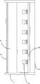
Fig. 1 is the structural representation of ultra-thin module one embodiment backlight of the utility model LED;
Fig. 2 is the structural representation of LED lamp bar unit shown in Figure 1.
The specific embodiment
As illustrated in fig. 1 and 2, in the ultra-thin module backlight of LED of the present utility model, it mainly compriseshousing 1 and the metal backing 2 and thediffuser plate 3 that are installed on thehousing 1, and lay respectively at the two ends ofhousing 1, between metal backing 2 anddiffuser plate 3, form certain space, in the outside ofdiffuser plate 3optical film assembly 4 is installed, among the embodiment as shown in Figure 1, thisoptical film assembly 4 is double-deck blooming, and is provided with light source assembly in the space that forms between metal backing 2 anddiffuser plate 3; This light source assembly is mainly partly formed by two, wherein a part for the speculum 6 that is arranged on metal backing 2 inboards be arranged on speculum 6 tops and with the LED lamp bar assembly of its maintenance certain distance; Innovative point of the present utility model is, this LED lamp bar assembly is oppositely installed, so that the light direction of this LED lamp bar assembly towards and perpendicular to speculum 6, in a preferred embodiment, speculum 6 is made by specular reflective material, and the characteristics of this specular reflective material are to form a mirror image to any object.When the LED lamp is luminous down, light can send downwards, reflect by specular reflective material, the LED lamp can be constituted a mirror image in reflecting material, this mirror image be equivalent to one with the identical light source of module light direction backlight, therefore be equivalent to increase the distance between led light source and the diffuser plate, the lamp shadow of lamp is had better disguise, can suitably reduce the distance between LED lamp bar assembly and thediffuser plate 3 thus, be beneficial to the ultra-thin making of whole LED module backlight.
For example, suppose that the distance between common LED module lamp backlight bar and the diffuser plate is a, the distance of lamp bar and reflector plate is b, distance between the utility model LED lamp bar and the diffuser plate is a, the distance of LED lamp bar and specular reflective material is d, and then the disguised parameter of common LED module backlight is a, and disguised parameter of the present utility model is 2d+a, clearly can reach a conclusion, the utility model can make whole LED module backlight become more ultra-thin.
As shown in Figure 1, this LED lamp bar assembly comprises at least one LEDlamp bar unit 5, and in this embodiment, this LED lamp bar assembly comprises many LED lamp bar unit 5.LEDlamp bar unit 5 comprises the LED lamp bar at least one LED lampbar bracing frame 54 and at least one LED lampbar bracing frame 54 of installation.As shown in figure 12, this LED lamp bar is supported by a plurality of LED lampbar bracing frames 54, and LED lamp bar comprises LEDlamp bar substrate 51 and at least one theLED lamp 52 that is installed on the LEDlamp bar substrate 51.
Among the embodiment as shown in Figure 2, on this LEDlamp bar substrate 51, a plurality ofLED lamps 52 are installed, are provided with printing opacity throughhole 53 between theadjacent LED lamp 52.
In a word, the technical solution of the utility model is after the employing specular reflective material, the LED lamp obtains a mirror image in specular reflective material inside, and the light Rotate 180 degree that mirror image can send the LED lamp is equivalent to light source at the mirror image place, thereby has increased light to the distance between the diffuser plate.
The utility model describes by several specific embodiments, it will be appreciated by those skilled in the art that, under the situation that does not break away from the utility model scope, can also carry out various conversion and be equal to alternative the utility model.In addition, at particular condition or concrete condition, can make various modifications to the utility model, and not break away from scope of the present utility model.Therefore, the utility model is not limited to disclosed specific embodiment, and should comprise the whole embodiments that fall in the utility model claim scope.
Claims (5)
1. the ultra-thin module backlight of LED comprises housing and the metal backing and the diffuser plate that are installed on the described housing, in the outside of described diffuser plate optical film assembly is installed, and it is characterized in that, is provided with light source assembly between described metal backing and diffuser plate; Described light source assembly comprises the speculum that is arranged on the metal backing inboard and is arranged on the LED lamp bar assembly of described speculum top; The light direction of described LED lamp bar assembly towards and perpendicular to described speculum, to form the mirror image light source.
2. the ultra-thin module backlight of LED according to claim 1 is characterized in that, described LED lamp bar assembly comprises at least one LED lamp bar unit.
3. the ultra-thin module backlight of LED according to claim 2 is characterized in that, described LED lamp bar unit comprises the LED lamp bar at least one LED lamp bar bracing frame and described at least one the LED lamp bar bracing frame of installation.
4. the ultra-thin module backlight of LED according to claim 3 is characterized in that, described LED lamp bar comprises LED lamp bar substrate and at least one the LED lamp that is installed on the described LED lamp bar substrate.
5. the ultra-thin module backlight of LED according to claim 4 is characterized in that, on described LED lamp bar substrate a plurality of LED lamps is installed, and is provided with the printing opacity through hole between the adjacent LED lamp.
Priority Applications (1)
| Application Number | Priority Date | Filing Date | Title |
|---|---|---|---|
| CN2009202061080UCN201547597U (en) | 2009-10-30 | 2009-10-30 | LED ultrathin backlight module |
Applications Claiming Priority (1)
| Application Number | Priority Date | Filing Date | Title |
|---|---|---|---|
| CN2009202061080UCN201547597U (en) | 2009-10-30 | 2009-10-30 | LED ultrathin backlight module |
Publications (1)
| Publication Number | Publication Date |
|---|---|
| CN201547597Utrue CN201547597U (en) | 2010-08-11 |
Family
ID=42602771
Family Applications (1)
| Application Number | Title | Priority Date | Filing Date |
|---|---|---|---|
| CN2009202061080UExpired - Fee RelatedCN201547597U (en) | 2009-10-30 | 2009-10-30 | LED ultrathin backlight module |
Country Status (1)
| Country | Link |
|---|---|
| CN (1) | CN201547597U (en) |
Cited By (6)
| Publication number | Priority date | Publication date | Assignee | Title |
|---|---|---|---|---|
| CN104424858A (en)* | 2013-08-26 | 2015-03-18 | 深圳市康硕展电子有限公司 | Backlight LED display screen |
| CN105156941A (en)* | 2015-07-06 | 2015-12-16 | 高创(苏州)电子有限公司 | Backlight module and display device |
| CN105242454A (en)* | 2015-10-15 | 2016-01-13 | 广州创维平面显示科技有限公司 | Ultrathin direct illumination-type backlight module and liquid crystal display device |
| CN106324904A (en)* | 2016-08-29 | 2017-01-11 | 合肥惠科金扬科技有限公司 | Vertical downward backlight module |
| WO2017215193A1 (en)* | 2016-06-17 | 2017-12-21 | Boe Technology Group Co., Ltd. | Backlight module and display device |
| CN112363349A (en)* | 2020-11-03 | 2021-02-12 | 广州长嘉电子有限公司 | Back-side backlight ultrathin frame-free television |
- 2009
- 2009-10-30CNCN2009202061080Upatent/CN201547597U/ennot_activeExpired - Fee Related
Cited By (8)
| Publication number | Priority date | Publication date | Assignee | Title |
|---|---|---|---|---|
| CN104424858A (en)* | 2013-08-26 | 2015-03-18 | 深圳市康硕展电子有限公司 | Backlight LED display screen |
| CN105156941A (en)* | 2015-07-06 | 2015-12-16 | 高创(苏州)电子有限公司 | Backlight module and display device |
| US9983436B2 (en) | 2015-07-06 | 2018-05-29 | Boe Technology Group Co., Ltd. | Backlight module and display device |
| CN105242454A (en)* | 2015-10-15 | 2016-01-13 | 广州创维平面显示科技有限公司 | Ultrathin direct illumination-type backlight module and liquid crystal display device |
| WO2017215193A1 (en)* | 2016-06-17 | 2017-12-21 | Boe Technology Group Co., Ltd. | Backlight module and display device |
| US10260713B2 (en) | 2016-06-17 | 2019-04-16 | Boe Technology Group Co., Ltd. | Backlight module and display device |
| CN106324904A (en)* | 2016-08-29 | 2017-01-11 | 合肥惠科金扬科技有限公司 | Vertical downward backlight module |
| CN112363349A (en)* | 2020-11-03 | 2021-02-12 | 广州长嘉电子有限公司 | Back-side backlight ultrathin frame-free television |
Similar Documents
| Publication | Publication Date | Title |
|---|---|---|
| CN102767762B (en) | Backlight module | |
| CN201547597U (en) | LED ultrathin backlight module | |
| CN102620203B (en) | Backlight module and liquid crystal display device | |
| US10007051B2 (en) | Backlight module and display device | |
| CN201502963U (en) | LED backlight module with light guide plate | |
| CN105116610B (en) | A kind of backlight module | |
| CN202452298U (en) | Backlight module | |
| CN202647428U (en) | Laterally-entering type backlight module and display unit | |
| CN203744043U (en) | Backlight module and display device | |
| CN211826816U (en) | Backlight illumination device and HUD | |
| CN201517726U (en) | Led back light module | |
| CN107065061B (en) | Light guide plate and direct type backlight assembly | |
| CN202813043U (en) | LED backlight source | |
| CN105158970B (en) | A kind of backlight module and display panel | |
| US20150205165A1 (en) | Direct Backlight Module | |
| CN207301567U (en) | Backlight module, liquid crystal display module and terminal equipment | |
| CN101655203A (en) | ultra-thin backlight module | |
| CN217333071U (en) | Backlight module and display device | |
| US8931911B2 (en) | Lighting system and display apparatus using the same | |
| CN202118702U (en) | Backlight module | |
| CN201654391U (en) | Double-side liquid crystal display with straight downward light guide plate | |
| CN209725948U (en) | A kind of LED backlight optical texture | |
| CN102798059B (en) | Edge-lighting backlight module | |
| CN209746321U (en) | Anti-dazzle backlight module with stable structure | |
| CN208367380U (en) | Backlight module and display device |
Legal Events
| Date | Code | Title | Description |
|---|---|---|---|
| C14 | Grant of patent or utility model | ||
| GR01 | Patent grant | ||
| ASS | Succession or assignment of patent right | Owner name:FLAT PANEL DISPLAY TECHNOLOGY CENTER, NANHAI, FOSH | |
| C41 | Transfer of patent application or patent right or utility model | ||
| COR | Change of bibliographic data | Free format text:CORRECT: ADDRESS; FROM: 518053 KONKA GROUP, OVERSEAS CHINESE TOWN, NANSHAN DISTRICT, SHENZHEN CITY,GUANGDONG PROVINCE TO: 518053 NO.9008, SHENNAN AVENUE, OVERSEAS CHINESE CITY, NANSHAN DISTRICT, SHENZHEN CITY, GUANGDONG PROVINCE | |
| TR01 | Transfer of patent right | Effective date of registration:20101213 Address after:518053 Nanshan District, Guangdong overseas Chinese town Shennan Road, No. 9008, No. Co-patentee after:Foshan Nanhai Panel Display Technology Center Patentee after:Konka Group Co., Ltd. Address before:518053 Nanshan District, Guangdong, Oct Konka Group Patentee before:Konka Group Co., Ltd. | |
| C17 | Cessation of patent right | ||
| CF01 | Termination of patent right due to non-payment of annual fee | Granted publication date:20100811 Termination date:20121030 |