CN201521777U - tripod - Google Patents
tripodDownload PDFInfo
- Publication number
- CN201521777U CN201521777UCN2009201702862UCN200920170286UCN201521777UCN 201521777 UCN201521777 UCN 201521777UCN 2009201702862 UCN2009201702862 UCN 2009201702862UCN 200920170286 UCN200920170286 UCN 200920170286UCN 201521777 UCN201521777 UCN 201521777U
- Authority
- CN
- China
- Prior art keywords
- pipe fitting
- tripod
- gear
- leg
- transmission shaft
- Prior art date
- Legal status (The legal status is an assumption and is not a legal conclusion. Google has not performed a legal analysis and makes no representation as to the accuracy of the status listed.)
- Expired - Lifetime
Links
- 230000005540biological transmissionEffects0.000claimsabstractdescription77
- 230000007246mechanismEffects0.000claimsabstractdescription10
- 238000013016dampingMethods0.000claimsdescription9
- 239000000428dustSubstances0.000claimsdescription3
- 239000000463materialSubstances0.000claimsdescription2
- 210000002414legAnatomy0.000claims32
- NJPPVKZQTLUDBO-UHFFFAOYSA-NnovaluronChemical compoundC1=C(Cl)C(OC(F)(F)C(OC(F)(F)F)F)=CC=C1NC(=O)NC(=O)C1=C(F)C=CC=C1FNJPPVKZQTLUDBO-UHFFFAOYSA-N0.000claims30
- 239000000758substrateSubstances0.000claims8
- 239000012634fragmentSubstances0.000claims3
- 210000001699lower legAnatomy0.000claims3
- 230000001105regulatory effectEffects0.000claims3
- LENZDBCJOHFCAS-UHFFFAOYSA-NtrisChemical compoundOCC(N)(CO)COLENZDBCJOHFCAS-UHFFFAOYSA-N0.000claims3
- 230000003213activating effectEffects0.000claims1
- 230000015572biosynthetic processEffects0.000claims1
- 230000035515penetrationEffects0.000claims1
- 230000001737promoting effectEffects0.000claims1
- 239000002689soilSubstances0.000claims1
- 239000003381stabilizerSubstances0.000abstract1
- 230000001360synchronised effectEffects0.000abstract1
- 238000010586diagramMethods0.000description13
- 230000001681protective effectEffects0.000description11
- 238000009434installationMethods0.000description5
- 239000002184metalSubstances0.000description4
- 238000006243chemical reactionMethods0.000description3
- 239000012535impuritySubstances0.000description3
- 238000000034methodMethods0.000description3
- XLYOFNOQVPJJNP-UHFFFAOYSA-NwaterSubstancesOXLYOFNOQVPJJNP-UHFFFAOYSA-N0.000description3
- 230000009471actionEffects0.000description2
- 230000008901benefitEffects0.000description2
- 238000006073displacement reactionMethods0.000description2
- 230000000149penetrating effectEffects0.000description2
- 230000007704transitionEffects0.000description2
- 208000027418Wounds and injuryDiseases0.000description1
- 230000004308accommodationEffects0.000description1
- 230000000903blocking effectEffects0.000description1
- 230000008878couplingEffects0.000description1
- 238000010168coupling processMethods0.000description1
- 238000005859coupling reactionMethods0.000description1
- 230000006378damageEffects0.000description1
- 230000007547defectEffects0.000description1
- 230000000694effectsEffects0.000description1
- 208000014674injuryDiseases0.000description1
- 239000004579marbleSubstances0.000description1
- 230000004048modificationEffects0.000description1
- 238000012986modificationMethods0.000description1
- 230000008569processEffects0.000description1
- 125000006850spacer groupChemical group0.000description1
- 230000007480spreadingEffects0.000description1
- 230000000087stabilizing effectEffects0.000description1
Images


Landscapes
- Accessories Of Cameras (AREA)
Abstract
Description
Translated fromChinese技术领域technical field
本实用新型涉及一种用于稳定摄影器材或者其他仪器、器材的三脚架,特别是涉及一种各支脚可得以同步快速锁定的三脚架。The utility model relates to a tripod used for stabilizing photographic equipment or other instruments and equipment, in particular to a tripod whose legs can be locked synchronously and quickly.
背景技术Background technique
为了稳定摄影器材或者其他仪器以进行摄影、摄像或者操作,通常会使用三脚架来支撑该摄影器材或仪器。此类三脚架一般包括三支可伸缩支脚以及处于支脚顶部以支撑摄影器材或仪器的载物台。在使用时,需将三支可伸缩支脚分别拉伸至所需长度并分别锁定各个支脚的长度,然后使各支脚相对于载物台展开成所需角度并使其底部坐落于地面上,最后在载物台上固定摄影器材进行摄影或者对其他仪器或器材进行操作。In order to stabilize photographic equipment or other instruments for photography, video recording or operation, a tripod is usually used to support the photographic equipment or instruments. This type of tripod generally includes three telescopic legs and a stage on top of the legs to support photographic equipment or instruments. When in use, it is necessary to stretch the three telescopic legs to the required length and lock the length of each leg respectively, then make each leg unfold to the required angle relative to the loading platform and make its bottom sit on the ground, and finally Fix photographic equipment on the stage for photography or operate other instruments or equipment.
目前,市场上的三脚架主要着重于降低其重量,以求携带方便。然而,展开和收起这些三脚架的操作相当繁琐、费时。以每支支脚包括三管件的三节型三脚架为例,连接每支支脚的三个管件就需两个关节,整个三脚架一共需六个关节。为了锁定各支脚的长度,就需对两个关节进行操作,以使与之连接的上、下管件相对锁定。从而,安装一个三脚架就需要对六个关节进行操作,使得安装这些三脚架的工作相当繁琐,所需安装时间也相对较长。At present, tripods on the market mainly focus on reducing their weight for easy portability. However, the operation of unfolding and stowing these tripods is rather tedious and time-consuming. Taking a three-section tripod with three pipes on each leg as an example, two joints are needed to connect the three pipes on each leg, and the whole tripod needs six joints in total. In order to lock the length of each leg, it is necessary to operate the two joints so that the upper and lower pipes connected thereto are relatively locked. Therefore, six joints need to be operated to install a tripod, which makes the work of installing these tripods rather cumbersome, and the required installation time is relatively long.
虽然,为便于安装,大部分三脚架的关节采用了“快锁系统”。当需锁定各管件时,仅需要拨动快锁系统的锁扣,就可以“啪”的一声锁定两相邻管件。对三节型三脚架而言,需要“啪”六声才能锁定各支脚的长度,从而采用“快锁系统”的三脚架仍然达不到快速安装的效果。如果三脚架是包括四管件的四节型三脚架,则上述安装操作将更加繁琐、费时。Although, for ease of installation, the joints of most tripods use a "quick lock system". When it is necessary to lock each pipe fitting, it is only necessary to toggle the buckle of the quick lock system, and two adjacent pipe fittings can be locked with a "snap". For the three-section tripod, it takes six "pops" to lock the length of each leg, so the tripod using the "quick lock system" still cannot achieve the effect of quick installation. If the tripod is a four-section tripod including four pipe fittings, the above-mentioned installation operation will be more complicated and time-consuming.
这样,当面对突发事件需要进行“抢拍”时,这些传统三脚架的上述缺陷就更加暴露无遗。Like this, when needing to " rush to shoot " in the face of an emergency, the above-mentioned defects of these traditional tripods are just more exposed.
当拍摄或操作完毕或者需要转换地方继续拍摄或操作时,需要通过反向进行上述操作来收起三脚架,然而,这种反向操作同样非常繁琐、费时。When the shooting or operation is finished or the place needs to be changed to continue shooting or operation, the tripod needs to be folded up by performing the above operations in reverse. However, this reverse operation is also very cumbersome and time-consuming.
另外,每支支脚底部会连接一个脚钉,以将三脚架坐落于地面上。然而,为了适应不同场地的需要,一套三脚架通常包括塑料脚钉和金属脚钉。当三脚架将坐落于木质、大理石地面上而需保护地面时,就需要在三脚架底部连接塑料脚钉。当三脚架将坐落于户外雪地、泥地而需要将脚钉插入地面时,就需要在三脚架底部连接金属脚钉。在上述情况下,传统的三脚架需拆卸原本的脚钉,以换上另一类型的脚钉。这更增加了三脚架安装的繁琐程度。Additionally, a spike is attached to the bottom of each leg to allow the tripod to rest on the ground. However, in order to adapt to the needs of different venues, a set of tripods usually includes plastic spikes and metal spikes. When the tripod will sit on wooden or marble floors and the ground needs to be protected, it is necessary to attach plastic spikes to the bottom of the tripod. When the tripod will be located outdoors on snow or mud and the spikes need to be inserted into the ground, it is necessary to connect metal spikes to the bottom of the tripod. In the above cases, traditional tripods need to disassemble the original spikes and replace them with another type of spikes. This adds to the complexity of tripod installation.
实用新型内容Utility model content
本实用新型的目的在于提供一种三脚架,以解决上述问题。The purpose of this utility model is to provide a tripod to solve the above problems.
本实用新型的目的是这样实现的,即提出一种三脚架,其包括:基座;三支枢转地设置于该基座周边的支脚,各支脚包括第一管件和第二管件,该第二管件可伸缩地套装于该第一管件内;设置于各支脚的第一管件和第二管件之间的第一锁定机构,其相对于该第一管件锁定该第二管件以阻止该第二管件相对于该第一管件伸缩移动;三组传动链,分别从该基座延伸至各支脚中并与相应的第一锁定机构相耦合,以驱动相应的第一锁定机构对第二管件进行锁定或解锁;致动机构,设置于该基座中并同步耦合该三组传动链以对其进行致动。The purpose of this utility model is achieved by proposing a tripod, which includes: a base; three legs pivotally arranged on the periphery of the base, each leg includes a first pipe and a second pipe, the second a pipe is telescopically sleeved within the first pipe; a first locking mechanism disposed between the first pipe and the second pipe of each leg, which locks the second pipe relative to the first pipe to prevent the second pipe from Telescopic movement relative to the first pipe; three sets of transmission chains respectively extend from the base to each leg and are coupled with the corresponding first locking mechanism to drive the corresponding first locking mechanism to lock or lock the second pipe; Unlocking; the actuating mechanism is arranged in the base and synchronously couples the three sets of transmission chains to actuate them.
另外,该三脚架还可包括三组支脚角度调节单元,其分别设置于该基座和各支脚连接件之间,以相对于该基座选择性锁定相应支脚而阻止相应支脚相对于该基座枢转;该三组支脚角度调节单元耦合于该致动组件,以在该致动组件致动下相对于该基座解锁相应支脚。In addition, the tripod can also include three sets of leg angle adjustment units, which are respectively arranged between the base and each leg connector, so as to selectively lock the corresponding legs relative to the base and prevent the corresponding legs from pivoting relative to the base. turn; the three sets of foot angle adjustment units are coupled to the actuating assembly, so as to unlock the corresponding feet relative to the base under the actuation of the actuating assembly.
本实用新型的优点在于,本实用新型的三脚架的各个支脚可得以同步快速锁定,从而可以快速展开该三脚架。The utility model has the advantage that each leg of the tripod of the utility model can be locked synchronously and quickly, so that the tripod can be quickly deployed.
附图说明Description of drawings
通过下面结合附图对本实用新型做出的详细说明,本实用新型的上述和/或其它特点和优点将变得更加清楚,图中各组件或部件仅是示意性的,而并没有按照比例绘示,其中:The above-mentioned and/or other characteristics and advantages of the present invention will become more clear through the detailed description of the present invention in conjunction with the accompanying drawings, and each component or component in the figure is only schematic and not drawn to scale. shown, where:
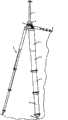
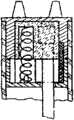
图1是本实用新型三脚架在收起状态下的示意图;Fig. 1 is the schematic diagram of the tripod of the present invention in a retracted state;
图2是本实用新型三脚架在展开状态下的示意图;Fig. 2 is a schematic diagram of the tripod of the present invention in an unfolded state;
图3是图1所示三脚架的俯视图;Fig. 3 is a top view of the tripod shown in Fig. 1;
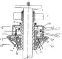
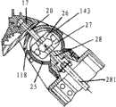
图4是本实用新型三脚架沿图3中A-A截面剖开的剖视图;Fig. 4 is the sectional view that the tripod of the present invention is cut along the section A-A in Fig. 3;
图5是本实用新型三脚架沿图3中B-B截面剖开的剖视图;Fig. 5 is the sectional view that tripod of the present invention is cut along the B-B section in Fig. 3;
图6是本实用新型三脚架中的基座的分解示意图;Fig. 6 is an exploded schematic view of the base in the tripod of the present invention;
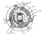
图7是本实用新型三脚架的基座沿图4中C-C截面剖开的剖视图;Fig. 7 is the sectional view that the base of the tripod of the present invention is cut along the C-C section in Fig. 4;
图8是本实用新型三脚架的转盘的仰视图;Fig. 8 is the bottom view of the turntable of the tripod of the present invention;
图9是本实用新型三脚架的转盘的俯视图;Fig. 9 is a top view of the turntable of the tripod of the present invention;
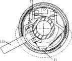
图10是本实用新型三脚架的基座沿图4中D-D截面剖开的示意图;Fig. 10 is the schematic diagram that the base of the tripod of the present invention is cut along the D-D section in Fig. 4;
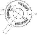
图11是示出本实用新型三脚架的手柄处于抬起状态下防尘盖板所处状态的示意图;Fig. 11 is a schematic view showing the state of the dust-proof cover when the handle of the tripod of the present invention is lifted;
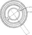
图12是本实用新型三脚架的基座沿图4中E-E截面剖开的示意图,其示出在本实用新型三脚架的手柄处于锁定状态下防尘侧板所处状态;Figure 12 is a schematic diagram of the base of the tripod of the present invention cut along the E-E section in Figure 4, which shows the state of the dust-proof side plate when the handle of the tripod of the present invention is in a locked state;
图13是本实用新型三脚架的基座沿图4中E-E截面剖开的示意图,其示出在本实用新型三脚架的手柄处于松开状态下防尘侧板所处状态的示意图;Fig. 13 is a schematic diagram of the base of the tripod of the present invention cut along the E-E section in Fig. 4, which shows a schematic view of the state of the dust-proof side plate when the handle of the tripod of the present invention is in a loose state;
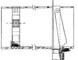
图14是本实用新型三脚架在收起状态下的局部剖视侧视图;Fig. 14 is a partial sectional side view of the tripod of the present invention in a retracted state;
图15是本实用新型三脚架在展开状态下的局部剖视侧视图;Fig. 15 is a partial sectional side view of the tripod of the present invention in an unfolded state;
图16和图17是示出本实用新型三脚架的基座与支脚连接关系的示意图;Fig. 16 and Fig. 17 are schematic diagrams showing the connection relationship between the base and the legs of the tripod of the present invention;
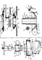
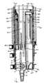
图18是本实用新型三脚架的支脚沿图14中F-F截面剖开的剖视图;Fig. 18 is a sectional view of the legs of the tripod of the present invention cut along the F-F section in Fig. 14;
图19是本实用新型三脚架的支脚沿图14中G-G截面剖开的剖视图;Fig. 19 is a cross-sectional view of the legs of the tripod of the present invention along the section G-G in Fig. 14;
图20是本实用新型三脚架的支脚沿图14中H-H截面剖开的剖视图;Fig. 20 is a cross-sectional view of the legs of the tripod of the present invention along the section H-H in Fig. 14;
图21是本实用新型三脚架的支脚沿图14中I-I截面剖开的剖视图;Fig. 21 is the cross-sectional view of the legs of the tripod of the present invention cut along the section I-I in Fig. 14;
图22是本实用新型三脚架的支脚沿图14中J-J截面剖开的剖视图;Fig. 22 is a sectional view of the legs of the tripod of the present invention cut along the J-J section in Fig. 14;
图23是本实用新型三脚架的支脚沿图14中K-K截面剖开的剖视图;Fig. 23 is a sectional view of the legs of the tripod of the present invention cut along the K-K section in Fig. 14;
图24是本实用新型三脚架的支脚沿图14中L-L截面剖开的剖视图;Fig. 24 is a sectional view of the legs of the tripod of the present invention cut along the L-L section in Fig. 14;
图25是本实用新型三脚架的支脚沿图14中M-M截面剖开的剖视图;Fig. 25 is a cross-sectional view of the legs of the tripod of the present invention cut along the M-M section in Fig. 14;
图26是本实用新型三脚架的支脚沿图15中N-N截面剖开的剖视图;Fig. 26 is a sectional view of the legs of the tripod of the present invention cut along the N-N section in Fig. 15;
图27是本实用新型三脚架的支脚沿图15中O-O截面剖开的剖视图;Fig. 27 is a sectional view of the legs of the tripod of the present invention cut along the O-O section in Fig. 15;
图28是本实用新型三脚架的支脚沿图15中P-P截面剖开的剖视图;Fig. 28 is a sectional view of the legs of the tripod of the present invention cut along the P-P section in Fig. 15;
图29是本实用新型三脚架的支脚沿图15中Q-Q截面剖开的剖视图;Fig. 29 is a sectional view of the legs of the tripod of the present invention cut along the Q-Q section in Fig. 15;
图30是本实用新型三脚架的支脚沿图15中R-R截面剖开的剖视图;Figure 30 is a sectional view of the legs of the tripod of the present invention cut along the R-R section in Figure 15;
图31是本实用新型三脚架的支脚沿图15中S-S截面剖开的剖视图;Fig. 31 is a sectional view of the legs of the tripod of the present invention cut along the S-S section in Fig. 15;
图32是本实用新型三脚架的支脚沿图15中T-T截面剖开的剖视图;Fig. 32 is a sectional view of the legs of the tripod of the present invention cut along the T-T section in Fig. 15;
图33是本实用新型三脚架的支脚沿图15中U-U截面剖开的剖视图;Fig. 33 is a sectional view of the legs of the tripod of the present invention cut along the U-U section in Fig. 15;
图34示出本实用新型三脚架的手柄处于锁定状态下转盘与各齿轮之间的位置关系;Figure 34 shows the positional relationship between the turntable and each gear when the handle of the tripod of the present invention is in a locked state;
图35示出本实用新型三脚架的手柄处于松开状态下转盘与各齿轮之间的位置关系;Figure 35 shows the positional relationship between the turntable and each gear when the handle of the tripod of the present invention is in a loose state;
图36是本实用新型三脚架传动关系示意图;Fig. 36 is a schematic diagram of the transmission relationship of the tripod of the present invention;
图37是本实用新型三脚架支脚的解锁单元初始状态的立体图;Fig. 37 is a perspective view of the initial state of the unlocking unit of the tripod leg of the utility model;
图38是本实用新型三脚架支脚的解锁单元初始状态的示意图;Fig. 38 is a schematic diagram of the initial state of the unlocking unit of the tripod leg of the present invention;
图39是本实用新型三脚架支脚的解锁单元工作状态的立体图;Fig. 39 is a perspective view of the working state of the unlocking unit of the tripod leg of the utility model;
图40是本实用新型三脚架支脚的解锁单元工作状态的示意图;Fig. 40 is a schematic diagram of the working state of the unlocking unit of the tripod leg of the present invention;
图41是示出本实用新型三脚架的脚钉与支脚的连接关系的剖视图;Fig. 41 is a cross-sectional view showing the connection relationship between the spikes and the legs of the tripod of the present invention;
图42是本实用新型三脚架的支脚沿图41中V-V截面剖开的剖视图;Figure 42 is a cross-sectional view of the legs of the tripod of the present invention cut along the V-V section in Figure 41;
图43是本实用新型三脚架的支脚沿图41中W-W截面剖开的剖视图;Figure 43 is a cross-sectional view of the legs of the tripod of the present invention along the W-W section in Figure 41;
图44是本实用新型三脚架的支脚沿图41中X-X截面剖开的剖视图;Fig. 44 is a cross-sectional view of the legs of the tripod of the present invention along the section X-X in Fig. 41;
图45是本实用新型三脚架的支脚沿图41的Y-Y截面剖开的剖视图;Fig. 45 is a sectional view of the legs of the tripod of the present invention cut along the Y-Y section of Fig. 41;
图46是示出本实用新型三脚架的阻尼装置吸气冲程的示意图;Fig. 46 is a schematic diagram showing the suction stroke of the damping device of the tripod of the present invention;
图47是示出本实用新型三脚架的阻尼装置排气冲程的示意图;Fig. 47 is a schematic diagram showing the exhaust stroke of the damping device of the tripod of the present invention;
图48是本实用新型三脚架的支脚沿图41的Z-Z截面剖开的剖视图,其示出本实用新型三脚架的脚钉组件定位单元;Fig. 48 is a sectional view of the legs of the tripod of the present invention cut along the Z-Z section of Fig. 41, which shows the positioning unit of the foot nail assembly of the tripod of the present invention;
图48A是本实用新型三脚架的脚钉组件定位单元中的曲线槽的示意图;Fig. 48A is a schematic diagram of the curved groove in the positioning unit of the foot nail assembly of the tripod of the present invention;
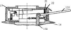
图49是示出本实用新型三脚架的脚钉组件处于伸出状态的示意图;以及Figure 49 is a schematic view showing that the foot nail assembly of the tripod of the present invention is in an extended state; and
图50是示出本实用新型三脚架的脚钉组件处于缩回状态的示意图,其中脚钉已经更换成金属脚钉。Fig. 50 is a schematic diagram showing the spike assembly of the tripod of the present invention in a retracted state, wherein the spikes have been replaced with metal spikes.
具体实施方式Detailed ways
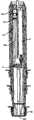
如图1和2所示,本实用新型的三脚架主要包括:基座1;三支枢转地设置于基座上的支脚2;竖直地贯穿基座并相对基座可上下移动的中轴3以及套装于中轴上以相对基座锁定中轴的中轴锁定器4。本实用新型三脚架的各支脚2至少包括两个管件,但是也可以包括三个或者更多管件。在图中所示实例中,各支脚2分别包括四个管件5、6、7、8。优选地,如图3所示,三支支脚2彼此均匀间隔开地布置于基座1周边。As shown in Figures 1 and 2, the tripod of the present invention mainly includes: a
参照附图3-14,基座1包括基座主体11、扣合于基座主体11上的基座内盖14以及设置于基座内盖14上的基座外盖15。在该基座主体11和基座内盖14之间可旋转地设置转盘12以及结合于转盘12以对其进行致动的致动组件13。另外,三组第一齿轮17在基座主体11和基座内盖14之间彼此间隔地设置于基座主体11侧部,以与转盘12相接触。三组彼此啮合的第二齿轮18和第三齿轮19也间隔开地设置于基座主体11侧部。Referring to FIGS. 3-14 , the
该基座主体11包括:底盆110,其上表面形成有容纳转盘12的凹陷111;从底盆110中央向上延伸的立柱112,其形成用以接纳中轴3的中心孔并且在其上部外表面上形成有外螺纹113;绕立柱112形成于凹陷111内的环形定位槽114,该定位槽114内形成的一对彼此相对的止动凸块1141(参见图7);彼此间隔开的从底盆110侧壁向外延伸的三组支架115(参见图6和14),各组支架分别包括两条间隔开的悬臂以用于支撑第二和第三齿轮18、19;邻近各支架115形成于底盆侧壁上的第一开口116,以供连接第一齿轮17的输出轴20伸出基座主体11;在各支架内形成于底盆110侧面上的第二开口117,以供第二齿轮18与凹陷111内的转盘12相接触;以及各第一开口116下侧形成的第一保护罩118。为了便于排出底盆110内的水或者杂质,可以在定位槽114内形成多个贯穿底盆110的导流孔1142。The
转盘12整体呈去顶圆锥体状,并形成有中心孔120,以便套装于基座主体立柱112上。转盘12包括彼此相对地形成于转盘底面上的一对定位块121,从而当将转盘12安装于基座主体11中时,定位块121座落于基座主体定位槽114中。各定位块121和基座主体定位槽114中相对应的止动凸块1141之间设置有弹簧122,其趋于将定位块121分别抵靠于另一止动凸块上(参见图7)。转盘12下表面外侧形成有环状凹面123。该凹面123上形成有三段彼此间隔的齿条124(参见图8),以分别与第二齿轮18选择性地啮合。在转盘12锥形侧面上绕转盘圆周形成有多个齿125(参见图9),以与第一齿轮17相啮合。转盘12的上表面绕中心孔120形成有沉孔126,以接纳致动组件13。在沉孔126内绕中心孔120形成有半圆形导向槽127。为了便于排出转盘12内的水或杂质,可在导向槽127内形成多个贯穿转盘12的导流孔1271。The
致动组件13包括:接纳于转盘沉孔126中的底板130;底板130中央形成有中心孔131,以套装于基座主体立柱112上;从底板130底面向下延伸的导向块132,其在将致动组件13安装于转盘12中时座落于转盘导向槽127中。转盘导向槽127中设置一对弹簧133,各弹簧两端分别抵靠在半圆形导向槽127的一端和导向块132上,以趋于使致动组件13处于中间平衡位置(参见图10)。致动组件13还包括从底板130的顶面向上延伸的支柱134,以及枢转地结合于支柱134顶端的手柄135,其中支柱134的高度确定为使其顶端处于基座内盖14上侧,而手柄135的末端延伸至基座外盖15外。The actuating
基座内盖14形成有中心孔140,以便套装于基座主体立柱112和致动组件的支柱134上。基座内盖14底面形成有与转盘沉孔126相对应的沉孔141,其扣合于致动组件的底板130上,以与转盘沉孔126相配合来限制致动组件13的纵向位移。基座内盖14底面间隔开地设置有三个凹状接纳槽142,以分别接纳第一齿轮17而使第一齿轮17与转盘侧面的齿125啮合。基座内盖侧面与基座主体第一保护罩118相对的位置上形成有第二保护罩143,第一、第二保护罩合抱成半圆筒状上保护罩(参见图5)。当将基座内盖14扣合于基座主体11上之后,可以通过连接件,例如螺钉(参见图4),将两者紧固,以限制两者之间容纳的部件的纵向位移。The base
基座外盖15形成容纳腔150,以供致动组件13的支柱134和手柄135的内端在其中转动,并且其顶部中央形成有中心孔151,以套装于基座主体立柱112上。基座外盖15的侧壁上形成有开口152,以供手柄135的外端伸出该基座外盖。该开口152中形成有“T”形凸起153(参见图1)。从而,手柄135可以从“T”形凸起的一侧转动到另一侧,而实现锁定与松开两种状态的转换,下文中将对其状态转换进行详细介绍。The base
该基座1还可以包括拧合于立柱112上部的外螺纹1131上的紧固螺母16,以将基座外盖15压靠于基座内盖14上,其中外螺纹1131形成于外螺纹113的下侧,且其外径大于外螺纹113的外径。The
中轴3套装于基座立柱112的中心孔中,且其上端设置有载物台31。载物台31顶面中央设置有螺纹杆32,以连接摄影器材或仪器(图中未示出)。中轴3底端可设置配重钩33,以悬挂配重(图中未示出)来稳定该三脚架。The
中轴锁定器4包括锁定器主体41和环形楔42。锁定器主体41形成有中心孔410且该中心孔内壁上形成有内螺纹411,其中,中心孔410的上端孔径小于下端孔径。该锁定器主体的内螺纹411与立柱112顶端的外螺纹113相啮合,同时环形楔42在中心孔410内设置于立柱112和中轴3之间。当需要锁定中轴3的位置时,就将锁定器主体更紧地拧合于外螺纹113上,从而向下挤压环形楔42,使其更紧地楔入立柱和中轴之间,达到锁定中轴的目的。当需要放松中轴3时,就通过拧松锁定器主体41来放松环形楔42。The
另外,为了减少灰尘进入基座内而对其中的活动部件造成阻滞,可在基座外盖15的容纳腔150内设置防尘上盖21。防尘上盖21包括供立柱112穿过的开口211和供防尘上盖21绕其枢转的枢轴212(参见图12)。基座外盖和基座内盖上分别设置有彼此扣合的上、下支撑件213、214,以支撑枢轴212。支撑片215在背离防尘上盖21的方向上从枢轴212延伸,其与下支撑件214之间设置有弹簧216。弹簧216趋于向上推动支撑片215,以将防尘上盖21压靠于手柄135上(参见图4)。由此,在手柄135沿“T”形凸起153移动时,防尘上盖21紧贴于手柄135上一起移动(参见图11)。In addition, in order to reduce dust entering into the base and blocking the moving parts therein, a dustproof
另外,为防止灰尘从开口152进入基座1内,可以绕基座外盖15内壁设置一对弧形防尘侧板22。防尘侧板22分别设置于手柄135两侧,并可滑动地座落于基座内盖14顶面形成的环形凹槽144中。各防尘侧板22分别通过弹簧221牵引,各弹簧221的两端分别固定于防尘侧板22远离手柄135的侧部和基座外盖15上,从而趋于将防尘侧板22压靠于手柄135上(参见图12和13)。由此,在手柄135沿开口152内的“T”形凸起移动时,防尘侧板22紧贴手柄135一起移动。In addition, in order to prevent dust from entering the
图14-40示出了本实用新型三脚架的支脚2及其与基座1的连接关系。本实用新型各支脚的结构相同,故在此仅以一支支脚为例进行说明。Fig. 14-40 shows the legs 2 of the tripod of the present invention and its connection relationship with the
支脚2通过支脚连接件23结合于基座1。支脚连接件23固定连接于支脚第一管件5的顶端,并包括一对从其顶面竖直向上延伸的连接片231。该对连接片231跨置于基座的支架115两侧,并借助第三齿轮19的支撑轴232枢转地连接于支架115上。在第三齿轮19与支脚连接件23顶面之间设置有支脚角度调节杆24,其靠近支脚内侧的端部241枢转连接于支脚连接件23上,而其靠近支脚外侧的端部为自由端。该调节杆24朝向第三齿轮19的上表面中部形成有多个齿243,以与第三齿轮19相啮合;而其朝向支脚连接件23的下表面中部受弹簧242支撑,以趋于将调节杆24中部的齿243推靠在第三齿轮19上(参见图5)。The legs 2 are combined with the
在支脚连接件23紧邻连接片231的位置上形成联接突起233,且其上设置有套合于上保护罩内的半圆筒状下保护罩25。A connecting protrusion 233 is formed at a position adjacent to the connecting piece 231 of the
各第一齿轮17的输出轴20延伸至由各自的上、下保护罩形成保护腔内,且在其末端连接有第一棘爪26。与第一棘爪26啮合地设置有第二棘爪27,该第二棘爪27同样处于保护腔内,且其输出轴28延伸至支脚2内并枢转地连接于支脚2内的第一柱状传动轴281。第一棘爪26和第二棘爪27可以是六爪棘爪。当使支脚2相对于基座1转动时,支脚连接件23的连接片231就相对于基座的支架115转动,与此同时下保护罩25就在上保护罩内转动,直至下保护罩和/或联接突起抵靠在上保护罩的下缘处。在此过程中,第一和第二棘爪26、27始终保持啮合(参见图16和17)。The
参见图14和图15,本实用新型的各支脚2包括四个管件,即第一管件5、第二管件6、第三管件7和第四管件8。第一管件5包括管状外壳51,该外壳51上下端开放,且其上端连接于支脚连接件23上。外壳51内壁上沿外壳51的整个高度形成有两组定位孔组52。这两组定位孔组52相对于外壳51中心呈角对称分布,且分别包括多个上下对齐的定位孔521(参见图18和26)。外壳51内壁底部形成有止动块53,以防止第二管件6完全移出第一管件5外,下文中将会对其进行详细介绍。Referring to FIG. 14 and FIG. 15 , each leg 2 of the present invention includes four pipes, that is, a first pipe 5 , a second pipe 6 , a third pipe 7 and a fourth pipe 8 . The first pipe member 5 includes a
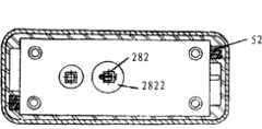
第二管件6包括可上下移动地套装于第一管件外壳51中的管状外壳61。一托架62固定于外壳61上端,并包括彼此间隔开的上、下托板。第一柱状传动轴281贯穿该托架62,并可相对该托架62自由旋转。受力齿轮63和作功齿轮64上下叠置地夹持于托架62的上下托板之间,且套装于第一柱状传动轴281上。受力齿轮63中心孔的横截面形成为矩形,且尺寸确定为稍大于第一柱状传动轴281横截面的尺寸,从而当将受力齿轮63套装于该第一柱状传动轴上时,其可沿该第一柱状传动轴的长度方向滑动,但是不可相对第一柱状传动轴旋转(参见图19和28)。然而,作功齿轮64中心孔的尺寸却确定为当其套装于第一柱状传动轴上时可相对于该第一柱状传动轴自由旋转(参见图20和28)。受力齿轮63和作功齿轮64之间通过弹簧65连接,该弹簧一端固定于受力齿轮63上,而另一端固定于作功齿轮64上。从而,当第一柱状传动轴281旋转而带动受力齿轮63旋转时,受力齿轮63借助弹簧65带动作功齿轮64一起旋转。The second pipe 6 includes a tubular shell 61 movably fitted in the
第一柱状传动轴281下端设置有销钉2811和垫片2812,其中垫片2812设置于托架62上。该垫片2812的内孔为矩形,且尺寸稍大于柱状传动轴281横截面尺寸。从而,该垫片2812可以防止销钉2811进入作功齿轮64的中心孔内。A pin 2811 and a washer 2812 are disposed on the lower end of the first
从动齿轮66夹持于托架62的上下托板之间并与受力齿轮63相啮合。第二柱状传动轴282固定地结合于该从动齿轮66,并且可相对于该托架62自由旋转地向下延伸。例如,该从动齿轮66形成有横截面为矩形的中心孔(参见图19),并且尺寸确定为稍大于第二柱状传动轴282的尺寸,从而当将从动齿轮66套装于该第二柱状传动轴上时,其不可相对第二柱状传动轴旋转。The driven
另外,在第二柱状传动轴紧邻托架62上下托板的位置处设置销钉2821和垫片2822,其中垫片2822处于销钉2821和上下托板之间,从而以防止第二柱状传动轴282相对于从动齿轮66进行纵向移动(参见图29)。同时,由于垫片2822可以将第二柱状传动轴282的纵向推力分散到托架62上,从而可以使得从动齿轮66两端不会承受过大的纵向推力。In addition, a pin 2821 and a
支脚第二管件6还包括设置于托架62内的止动单元69和推力弹簧692(参见图21和30)。该止动单元69一端枢转地设置于托架62内并包括朝向托架62外延伸的止动凸起691。该推力弹簧692一端抵靠在托架62上,而另一端抵靠在止动单元上,以趋于将止动凸起691推出贯穿外壳61和托架62侧壁的开口611。由此,当第二管件6的上端滑动至第一管件5的末端时,止动单元69的止动凸起691将从上接触并抵靠在第一管件的止动块53上,从而阻止第二管件6滑出第一管件5外。The second pipe member 6 of the leg further includes a
为了在收起支脚第二管件时相对于第一管件锁定该第二管件,该第二管件6还包括设置于作功齿轮64一侧的锁定单元67(参见图20和37)。该锁定单元包括:基板671;在基板面对作功齿轮64的一端形成的齿条672,该齿条与作功齿轮啮合;以及基板671上与形成齿条的一端相对的端部形成的分叉端673。该分叉端673包括至少一个与第一管件5上的定位孔521相配合的定位销6731。同时,在第二管件6的外壳61和托架62上形成有供定位销6731穿过的开口612。从而,当作功齿轮64顺时针转动(从上侧观察)时,其借助齿条672驱动基板671朝向开口612移动,使得分叉端673的定位销6731穿过托架和外壳而插入第一管件5的定位孔521中,从而锁定第一和第二管件,而无法拉伸第二管件。In order to lock the second pipe part relative to the first pipe part when the second pipe part of the leg is retracted, the second pipe part 6 further includes a
优选地,为了保持平衡,可以为该第二管件6设置另一锁定单元68,该锁定单元68与锁定单元67相对于作功齿轮64成角对称分布,从而其分叉端的定位销可以选择性地插入第一管件的另一组定位孔组的定位孔中。由于两锁定单元结构基本相似,在此不再进行赘述。Preferably, in order to maintain balance, another locking
为了可以在整个支脚位置被锁定的情况下对第二管件6伸出第一管件5的长度进行微调,可在第二管件6上设置解锁单元60,其包括:设置在第二管件外壳61下部的牵引单元601;设置于锁定单元基板671侧表面的致动块602;靠近致动块602而可上下移动的设置于托架62内致动楔603;推力弹簧604,其两端分别抵靠在托架62和致动楔603上,以趋于将致动楔603推离致动块602;以及牵引索605,其一端固定于致动楔603上,而另一端穿过第二管件6的外壳61而固定于牵引单元601上(参见图27)。该牵引单元601包括固定于外壳外表面的框架6011;可枢转地设置于该框架6011上的转臂6012;结合于转臂6012自由端的按压片6013。优选地,该按压片6013位于框架6011一侧形成的凹槽6014中。牵引索605固定于牵引单元601的一端就固定于按压片6013上(参见图38)。In order to be able to fine-tune the length of the second pipe 6 protruding from the first pipe 5 under the condition that the entire leg position is locked, an unlocking
从而,当按压该按压片6013时,牵引索605带动致动楔603克服推力弹簧604的推力而向下移动,由此借助致动块602推动锁定单元67朝向托架62内部移动,从而定位销6731移出定位孔521,使得可以第二管件6相对于第一管件5解锁而可以相对于后者移动。Therefore, when the
在第二管件6包括锁定单元68的情况下,锁定单元67的齿条672驱使作功齿轮64逆时针转动(从上侧观察),由此带动锁定单元68同时朝向托架62内部移动,从而锁定单元68的定位销也从第一管件的定位孔中移出而解除第一、第二管件之间的锁定(参见图39和40)。In the case that the second pipe member 6 includes the locking
当调整好第二管件6相对于第一管件5的位置而释放按压片6013后,推力弹簧604将致动楔603推离致动块602,从而在弹簧65的回复作用力下,作功齿轮64重新进行顺时针旋转,驱动两锁定单元朝向托架62外移动,从而相对于第一管件5重新锁定第二管件6。After adjusting the position of the second pipe 6 relative to the first pipe 5 and releasing the
另外,在第二管件外壳61上与第一管件5的定位孔组52错开的位置上沿着整个外壳61高度上形成有两组定位孔组613。这两组定位孔组613分别包括多个上下对齐的定位孔6131(参见图36)。另外,在第二管件6外壳61底部形成有止动孔614(参见图15),以防止第三管件7完全移出第二管件6,下文中将会对其进行详细介绍。In addition, two sets of
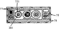
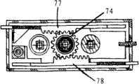
在第三管件7的托架72对应于第一柱状传动轴281的位置形成有纵向贯穿孔721,以在支脚收起时供第一柱状传动轴281穿过(参见图21、22)。当第三管件7的上端滑动至第二管件6的末端时,第三管件7的止动单元79的止动凸起791结合于第二管件6的止动孔614中,从而阻止第三管件7滑出第二管件6。另外,第三管件7的锁定单元77和78与第二管件6的锁定单元67和68形成交错布置。从而,第三管件7的作功齿轮74顺时针旋转(从上侧观察)可以驱使锁定单元77和78朝向托架72内移动。除以上不同之处外,第三管件7的结构与第二管件6类似,故不在此进行赘述。A longitudinal through
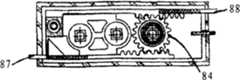
如图15和图32-33所示,在第四管件8的托架82对应于第一柱状传动轴281的位置形成第一纵向贯穿孔821,以在支脚收起时供第一柱状传动轴281穿过;而在其对应于第二柱状传动轴282的位置形成第二纵向贯穿孔822,以在支脚收起时供第二柱状传动轴282穿过(参见图24-25和图32)。第四管件8的锁定单元87和88与第三管件7的锁定单元77和78形成交错布置。从而,第四管件8的作功齿轮84逆时针旋转(从上侧观察)可以驱使锁定单元87和88朝向托架82内移动。另外,如果第四管件8为支脚的末端管件,则该管件可以不包括从动齿轮及相对于该从动齿轮固定设置的柱状传动轴。除以上不同之处外,第四管件8的结构与第三管件7类似,故不在此进行赘述。As shown in Fig. 15 and Figs. 32-33, a first longitudinal through
下面结合图34-36详细描述本实用新型三脚架的工作方式。The working mode of the tripod of the present utility model is described in detail below in conjunction with Fig. 34-36.
当致动组件13的手柄135处于图34所示的锁紧位置时,也就是处于图1中所示的“T”形凸起右侧位置时,致动组件13的导向块132在转盘12的导向槽127中处于平衡位置,而使得转盘12在弹簧122的作用下处于其初始位置。此时,第二齿轮18与转盘的齿条124相啮合,故第二齿轮18无法自由旋转。由于第二齿轮18与第三齿轮19啮合(参见图5),而第三齿轮19与支脚角度调节杆24的齿243相啮合,从而第三齿轮19无法转动,而支脚角度调节杆24也无法相对于第三齿轮19进行转动,由此一端固定的设置于支脚上的支脚角度调节杆24就可以阻止支脚相对于基座1转动而向外张开。When the
与此同时,由于转盘12保持静止,与其侧面的齿125啮合的第一齿轮17也保持静止,从而其输出轴20和棘爪26不会驱使支脚的第一柱状传动轴281转动。从而,支脚的第二至第四管件的锁定单元处于伸出相应外壳的初始位置,而其各自的定位销也处于插入上一管件的定位孔的初始状态,由此各个支脚相邻管件分别处于锁定状态,而不能进行拉伸。At the same time, since the
当致动组件13的手柄135被转动至图35所示的松开位置时,也就是处于图1中所示的“T”形凸起左侧位置时,致动组件13的导向块132在转盘12的导向槽127顺时针转动(从上侧观察),并且同时借助弹簧133推动转盘12一起顺时针转动。由于转盘12的转动,第二齿轮18与转盘的齿条124相脱离,故第二齿轮18此时可以在转盘12的环形凹面123内自由旋转。由于第二齿轮18与第三齿轮19啮合(参见图5),而第三齿轮19与支脚角度调节杆24的齿243相啮合,这样第三齿轮19此时也可以旋转,从而支脚角度调节杆24可以驱使第二齿轮18和第三齿轮19进行转动。由此,当相对于基座1转动支脚时,一端固定的设置于支脚上的支脚角度调节杆24可以驱动第二齿轮18和第三齿轮19自由转动,而不受任何阻碍。这样就使得了各支脚2可以相对于基座1进行转动而展开一定角度。When the
与此同时,由于转盘12顺时针转动,与其侧面的齿125啮合的第一齿轮17就逆时针转动(从基座内向外观察),从而第一齿轮的输出轴20经由第一棘爪26、第二棘爪27以及第二棘爪输出轴28驱使支脚2的第一柱状传动轴281逆时针旋转(从上侧观察)。第一柱状传动轴281驱动受力齿轮63逆时针旋转,而受力齿轮63又经由弹簧65带动作功齿轮64逆时针旋转,从而作功齿轮64借助齿条驱动锁定单元67和68朝托架62内移动,以使锁定单元的锁定销从第一管件5中的定位孔中移出,而在支脚的第一管件5和第二管件6之间进行解锁。At the same time, due to the clockwise rotation of the
与此同时,受力齿轮63驱使从动齿轮66顺时针旋转(从上侧观察),从动齿轮66带动第二柱状传动轴282一起顺时针旋转。与上面运作类似的,第二柱状传动轴282驱动第三管件7的受力齿轮73顺时针旋转,而受力齿轮73又经由弹簧75带动作功齿轮74顺时针旋转,从而作功齿轮74借助锁定单元77和78的齿条驱动锁定单元77和78朝托架72内移动,以使第三管件的锁定单元的锁定销从第二管件6中的定位孔中移出,而在支脚的第二管件6和第三管件7之间进行解锁。At the same time, the driven
依次类推,支脚的第三管件7和第四管件8之间也进行解锁。从而,通过上述传动方式,各个支脚的相邻管件之间的锁定都得以解除,从而可以将各个管件从其上一管件中拉出所需长度。By analogy, unlocking is also performed between the third pipe member 7 and the fourth pipe member 8 of the support leg. Therefore, through the above-mentioned transmission mode, the locking between the adjacent pipe parts of each leg is released, so that each pipe part can be pulled out to a required length from the previous pipe part.
当调整好各个支脚的长度和其相对于基座展开的角度后,可以将手柄135转回到锁定位置,也即图1所示的“T”形凸起右侧位置,来锁定支脚。当将手柄135转回锁定位置时,转盘12在弹簧122的作用下被转动到图34所示的位置,从而各个支脚的第二齿轮18、第三齿轮19以及支脚角度调节杆24被重新锁定,由此各个支脚相对于基座的展开角度就被锁定。After adjusting the length of each leg and its angle relative to the base, the
另外,在转盘12转回图34所示位置的过程中,其带动各支脚的第一齿轮17顺时针转动(从基座内向外观察),从而各管件中的柱状传动轴、受力齿轮、作功齿轮、从动齿轮按照与解锁操作相反的方向转动,驱使各管件的锁定单元朝向各自的托架外移动,从而各锁定单元的锁定销将分别重新插入上一管件的定位孔组中的定位孔中,以重新锁定各支脚的相邻管件。In addition, when the
从而,在调整好各支脚的拉伸长度和展开角度后,本实用新型仅需将手柄135转回到锁定位置,也即图1中所示的“T”形凸起右侧位置,就可以同步锁定所有支脚,包括各支脚相对于基座展开的角度及各支脚伸展的长度。Thereby, after adjusting the stretching length and deployment angle of each leg, the utility model only needs to turn the
在手柄处于锁定位置的状态下,为了微调各个支脚相对于基座的展开角度,可以按压支脚角度调节杆24的自由端(参见图5),来克服弹簧242的弹力而使该调节杆的齿243与第三齿轮19相脱离,从而可以相对于基座1自由转动支脚2,而不受第二和第三齿轮不能旋转的限制。When the handle is in the locked position, in order to fine-tune the deployment angle of each leg relative to the base, you can press the free end of the leg angle adjustment lever 24 (see Figure 5) to overcome the elastic force of the
同样,在手柄处于锁定位置的状态下,为了微调各个管件的伸出长度,可以按压其解锁单元的按压片(参见图37-40),使得牵引索带动致动楔抵抗推力弹簧的推力而向下移动,从而借助致动块推动锁定单元朝向托架内部移动,从而定位销移出定位孔,使得可以解除该管件与其上一管件之间的锁定。Similarly, when the handle is in the locked position, in order to fine-tune the protruding length of each pipe, you can press the pressing piece of the unlocking unit (see Figure 37-40), so that the traction cable drives the actuating wedge to resist the thrust of the thrust spring. Move down, thereby pushing the locking unit to move toward the inside of the bracket by means of the actuating block, so that the positioning pin moves out of the positioning hole, so that the locking between the pipe and its previous pipe can be released.
下面参照图41-50描述设置于本实用新型三脚架的各支脚末端的脚钉组件。41-50 will describe the foot nail assembly arranged at the end of each leg of the tripod of the present invention.
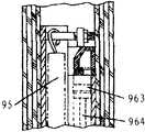
脚钉组件9设置于各支脚的末端管件中,例如,本示例的第四管件8中,并包括可上下移动地设置于支脚的第四管件内的支撑架91、设置于支撑架下端部的脚钉选择单元92、固定于脚钉选择单元上的第一脚钉93、与第一脚钉相对地固定于脚钉选择单元上的第二脚钉94、一端固定于支撑架91上而另一端固定于第四管件上的拉力弹簧95、设置于第四管件和支撑架之间的空气阻尼单元96以及脚钉组件定位单元97。The
支撑架91顶端开放并形成有供相应管件的柱状传动轴插入的腔体911。另外,在腔体911内部形成有通道912和913,其分别供第一柱状传动轴281和第二柱状传动轴282插入。各通道的尺寸稍大于相应柱状传动轴横截面的尺寸,以供柱状传动轴在其中自由旋转与自由进出。同时,由于各通道的尺寸仅稍大于柱状传动轴横截面的尺寸,从而当三脚架被收起来而横放收藏时,相应柱状传动轴插入通道中并受到通道侧壁承托。由此,可以避免柱状传动轴尾部长时间悬空而导致传动轴弯曲。The top end of the
第一脚钉93和第二脚钉94可以分别由不同材料制成,以适应不同场地的要求。例如,第一脚钉93可由塑料制成,以适用于室内场地;而第二脚钉94可由金属制成,以适用于室外场地。The first foot spikes 93 and the second foot spikes 94 can be made of different materials to meet the requirements of different venues. For example, the
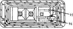
如图49所示,脚钉选择单元92包括:承载台921,其可转动地设置于支撑架91下端部,而第一脚钉93和第二脚钉94分别设置于该承载台921的两相对侧;选择盘922,其相对于支撑架91固定地设置于承载台921的中央位置,并且在其圆周上对称地形成有两个凹槽9221和9222;以及选择弹片923,其形成为U形,并且在其两末端位置形成有朝向U形内部的凸起9231和9232。该选择弹片923的凸起之间的距离略小于选择盘922的直径。选择弹片923的中间部位固定于承载台921,而其两凸起9231和9232则沿着选择盘922的直径而抵靠在选择盘922上。从而,当转动该承载台921而进行脚钉选择时,选择弹片923的两凸起就沿着选择盘922的圆周滑动,直至滑入选择盘922的凹槽中,实现对脚钉的定位。当需要转换脚钉时,则仅需将承载台921旋转180°,使得选择弹片923的两凸起滑入相对的选择盘的凹槽中,以实现脚钉转换。As shown in FIG. 49 , the
当需要转换脚钉时,则需要将支撑架91的下端部拉出支脚的第四管件8,而可以转动脚钉选择单元的承载台921以进行脚钉选择。当脚钉转换完成后,拉力弹簧95的拉力可以将支撑架91以及其上所承载的脚钉选择单元92拉回第四管件内,而仅露出被选择的脚钉。When it is necessary to switch the foot spikes, the lower end of the
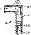
为了防止拉力弹簧95突然将支撑架91拉回第四管件8内而对使用者造成伤害,可在支撑架91和第四管件8之间设置空气阻尼单元96。如图46和47所示,该空气阻尼单元包括:竖直设置的第一气缸961;横向固定于在第一气缸末端并与第一气缸连通的第二气缸962;可移动地设置于第一气缸内的活塞963以及连接于活塞的活塞杆964。该第二气缸侧壁中形成有进气孔9621;膜片9622设置于气缸内壁对应于进气孔9621的位置上,以覆盖该进气孔。该膜片9622在远离第一气缸的一边固定,而其他边缘自由。另外,在第二气缸的气缸壁中还形成有出气孔9623,该出气孔9623的尺寸远小于进气孔9621的尺寸。从而,当活塞963受活塞杆964牵引而远离第二气缸时,空气主要经由进气孔9621进入第一、第二气缸内,从而活塞963可以快速滑动。然而,当活塞963由活塞杆964推动而靠近第二气缸时,第一、第二气缸内的空气需要排出,然而需排出的空气将膜片9622压靠在进气孔9621上,使得空气无法经过进气孔9621排出,而只能经由尺寸很小的出气孔9623排出。这样,活塞963在靠近第二气缸的移动中将收到较大的空气阻力而只能缓慢的滑动。In order to prevent the
该空气阻尼单元的第一气缸和第二气缸在第四管件内固定于第四管件或者脚钉组件的支撑架,而其活塞杆则相对地固定于支撑架或第四管件。从而,由于该空气阻尼单元的上述工作方式,当将支撑架拉出第四管件8时,活塞可以快速移动,从而可以快速将支撑架91拉出。然而,当拉力弹簧95将支撑架91拉回第四管件8内时,由于活塞受空气阻力作用而只能缓慢移动,导致支撑架91也只能缓慢移动至第四管件8内,从而起到安全保护的作用。The first air cylinder and the second air cylinder of the air damping unit are fixed to the support frame of the fourth pipe or the spike assembly in the fourth pipe, and the piston rod is relatively fixed to the support or the fourth pipe. Therefore, due to the above-mentioned working method of the air damping unit, when the support frame is pulled out of the fourth pipe member 8, the piston can move quickly, so that the
另外,在将脚钉选择单元92拉出第四管件8外以进行脚钉转换时,为了克服拉力弹簧95的拉力而防止支撑架91和脚钉选择单元92被自动拉回第四管件内,可以在第四管件8内设置脚钉组件定位单元97。该脚钉组件定位单元97包括定位杆971、形成于支撑架上曲线槽972以及用于将定位杆971一端压靠于曲线槽972中的弹簧973。该定位杆971的一端设置于第四管件8上,而另一端可滑动地结合于曲线槽972中。该曲线槽972构成为心形曲线槽(参见图48A),其包括依次连接的曲线段9721、9722、9723和9724构成,其中各线段相交处的槽深度大于各个线段自身的深度,并且后一条曲线段的起始处深度略大于前一条曲线段的终点处深度,从而可以保证定位杆971的端部不会入错曲线段或者往回滑动。另外,曲线段9721可以形成有不与其他曲线段相交的自由末端9720。当支撑架91和脚钉选择单元92处于第四管件8内时,定位杆971的滑动端处于曲线段9721的自由末端9720。当将支撑架91拉出第四管件时,定位杆的滑动端沿着曲线段9721向上滑动。当支撑架91被完全拉出时,该滑动端滑动至曲线段9721和9722之间的第一相交处。当释放该支撑架91时,由于受到拉力弹簧95的牵引,支撑架91局部退回支脚的第四管件8中,从而定位杆971的滑动端沿着曲线段9722滑动到曲线段9722和曲线段9723之间的第二相交处,并在此处于稳定状态,防止支撑架91进一步退回第四管件8中。当完成脚钉选择而需要支撑架91和脚钉选择单元92退回第四管件8中时,需要先向外拉动支撑架91,使得定位杆971的滑动端离开第二相交处,并沿着曲线段9723达到曲线段9723与曲线段9724之间的第三相交处,并越过第三相交处进入曲线段9724内。此时,放松支撑架91,则整个支撑架91以及脚钉选择单元92在拉力弹簧95的牵引下退回第四管件8中。同时,定位杆971的滑动端沿着曲线段9724滑动,并进入曲线段9721中,最后一直滑动到曲线段9721的自由末端9720,从而支撑架91和脚钉选择单元92就稳定地退回到第四管件8中。In addition, when the
另外,在第四管件8的末端可以设置底盖98,以封闭第四管件8末端未被脚钉组件9封闭的区域。该底盖98中可以设置通道981,其结构和作用与通道912和913相同,用以接纳并承载其他柱状传动轴,以避免这些柱状传动轴尾部长时间悬空而导致传动轴弯曲。在底盖98底部可以形成有贯穿底盖98的导流孔982,以便排出各支脚内的水或杂质。In addition, a
尽管上面已经详细描述了本发明的各种实施例,但是对于本领域技术人员来说,可以对本发明做出进一步的变化和改进。应当理解,这样的变化和改进在本发明的精神和范围之内。Although various embodiments of the present invention have been described in detail above, those skilled in the art can make further changes and improvements to the present invention. It should be understood that such changes and modifications are within the spirit and scope of the invention.
Claims (37)
Priority Applications (3)
| Application Number | Priority Date | Filing Date | Title |
|---|---|---|---|
| CN2009201702862UCN201521777U (en) | 2009-09-07 | 2009-09-07 | tripod |
| US12/875,386US8528868B2 (en) | 2009-09-07 | 2010-09-03 | Supporting device |
| PCT/CN2010/076647WO2011026444A1 (en) | 2009-09-07 | 2010-09-06 | Supporting device |
Applications Claiming Priority (1)
| Application Number | Priority Date | Filing Date | Title |
|---|---|---|---|
| CN2009201702862UCN201521777U (en) | 2009-09-07 | 2009-09-07 | tripod |
Publications (1)
| Publication Number | Publication Date |
|---|---|
| CN201521777Utrue CN201521777U (en) | 2010-07-07 |
Family
ID=42507952
Family Applications (1)
| Application Number | Title | Priority Date | Filing Date |
|---|---|---|---|
| CN2009201702862UExpired - LifetimeCN201521777U (en) | 2009-09-07 | 2009-09-07 | tripod |
Country Status (1)
| Country | Link |
|---|---|
| CN (1) | CN201521777U (en) |
Cited By (4)
| Publication number | Priority date | Publication date | Assignee | Title |
|---|---|---|---|---|
| WO2011026444A1 (en)* | 2009-09-07 | 2011-03-10 | Fung Ngo Leung | Supporting device |
| CN102011921A (en)* | 2009-09-07 | 2011-04-13 | 梁凤娥 | Tripod |
| CN110566778A (en)* | 2019-09-16 | 2019-12-13 | 张磊 | Rapid folding and unfolding tripod |
| CN115597102A (en)* | 2022-10-21 | 2023-01-13 | 珠海格力电器股份有限公司(Cn) | Base structure and heating installation |
- 2009
- 2009-09-07CNCN2009201702862Upatent/CN201521777U/ennot_activeExpired - Lifetime
Cited By (7)
| Publication number | Priority date | Publication date | Assignee | Title |
|---|---|---|---|---|
| WO2011026444A1 (en)* | 2009-09-07 | 2011-03-10 | Fung Ngo Leung | Supporting device |
| CN102011921A (en)* | 2009-09-07 | 2011-04-13 | 梁凤娥 | Tripod |
| CN102011921B (en)* | 2009-09-07 | 2014-06-25 | 梁凤娥 | Tripod |
| CN110566778A (en)* | 2019-09-16 | 2019-12-13 | 张磊 | Rapid folding and unfolding tripod |
| CN110566778B (en)* | 2019-09-16 | 2024-02-13 | 张磊 | Tripod capable of being quickly folded and unfolded |
| CN115597102A (en)* | 2022-10-21 | 2023-01-13 | 珠海格力电器股份有限公司(Cn) | Base structure and heating installation |
| CN115597102B (en)* | 2022-10-21 | 2024-05-10 | 珠海格力电器股份有限公司 | Base structure and heating device |
Similar Documents
| Publication | Publication Date | Title |
|---|---|---|
| US8528868B2 (en) | Supporting device | |
| CN102011921A (en) | Tripod | |
| CN201281215Y (en) | Reversible folding photographic tripod | |
| US6662815B2 (en) | Canopy support frame for a sunshade | |
| US6196242B1 (en) | Hanging sun umbrella | |
| CN201521777U (en) | tripod | |
| CA2609778C (en) | Locking mechanism for a ladder | |
| CN100565325C (en) | A kind of camera trivets | |
| US5651405A (en) | Portable acoustic shell | |
| WO2020093471A1 (en) | Sunshade capable of rotating to left and to right | |
| CN201438255U (en) | Foldable support curtain structure | |
| CN205919274U (en) | Support and have frame lamp of this support | |
| WO2006136066A1 (en) | A top fixing device for a collapsible semicircular tent framework | |
| US6006680A (en) | Portable stage assembly | |
| CN114673970A (en) | Emergency rescue lifting working lamp | |
| US20090071517A1 (en) | Dual function umbrella | |
| CN201175173Y (en) | Locking mechanism for baby bed frame | |
| CN110529714B (en) | Tripod capable of being quickly folded and unfolded | |
| CN210920807U (en) | Rapid folding tripod | |
| CN209421527U (en) | A children's bed body folding linkage unlocking control mechanism | |
| CN209421520U (en) | A kind of children's bed body folds gathering mechanism and its play yard | |
| CN210353521U (en) | Outdoor center pillar umbrella of manual rotatory dog-ear formula side pipe | |
| CN112160704B (en) | Novel bamboo joint ladder | |
| CN210813795U (en) | A portable badminton net frame structure | |
| CN221197249U (en) | A foldable cloth lamp bracket and a foldable cloth lamp |
Legal Events
| Date | Code | Title | Description |
|---|---|---|---|
| C14 | Grant of patent or utility model | ||
| GR01 | Patent grant | ||
| AV01 | Patent right actively abandoned | Granted publication date:20100707 Effective date of abandoning:20090907 | |
| AV01 | Patent right actively abandoned | Granted publication date:20100707 Effective date of abandoning:20090907 | |
| RGAV | Abandon patent right to avoid regrant |