CN201513461U - hub - Google Patents
hubDownload PDFInfo
- Publication number
- CN201513461U CN201513461UCN2009203072805UCN200920307280UCN201513461UCN 201513461 UCN201513461 UCN 201513461UCN 2009203072805 UCN2009203072805 UCN 2009203072805UCN 200920307280 UCN200920307280 UCN 200920307280UCN 201513461 UCN201513461 UCN 201513461U
- Authority
- CN
- China
- Prior art keywords
- shaft
- stopper
- interference
- piece
- connecting piece
- Prior art date
- Legal status (The legal status is an assumption and is not a legal conclusion. Google has not performed a legal analysis and makes no representation as to the accuracy of the status listed.)
- Expired - Fee Related
Links
Images


Classifications
- E—FIXED CONSTRUCTIONS
- E05—LOCKS; KEYS; WINDOW OR DOOR FITTINGS; SAFES
- E05D—HINGES OR SUSPENSION DEVICES FOR DOORS, WINDOWS OR WINGS
- E05D11/00—Additional features or accessories of hinges
- E05D11/08—Friction devices between relatively-movable hinge parts
- E05D11/087—Friction devices between relatively-movable hinge parts with substantially axial friction, e.g. friction disks
- E—FIXED CONSTRUCTIONS
- E05—LOCKS; KEYS; WINDOW OR DOOR FITTINGS; SAFES
- E05Y—INDEXING SCHEME ASSOCIATED WITH SUBCLASSES E05D AND E05F, RELATING TO CONSTRUCTION ELEMENTS, ELECTRIC CONTROL, POWER SUPPLY, POWER SIGNAL OR TRANSMISSION, USER INTERFACES, MOUNTING OR COUPLING, DETAILS, ACCESSORIES, AUXILIARY OPERATIONS NOT OTHERWISE PROVIDED FOR, APPLICATION THEREOF
- E05Y2999/00—Subject-matter not otherwise provided for in this subclass
Landscapes
- Engineering & Computer Science (AREA)
- Mechanical Engineering (AREA)
- Pivots And Pivotal Connections (AREA)
Abstract
Translated fromChinese
Description
Translated fromChinese技术领域technical field
本实用新型涉及一种枢纽器。The utility model relates to a hinge device.
背景技术Background technique
电子装置的上盖与底座之间一般通过枢纽器相连,以使上盖相对底座开启及闭合。The upper cover and the base of the electronic device are generally connected by a hinge so that the upper cover can be opened and closed relative to the base.
在现有技术中,为了避免上盖相对该底座的张开角度过大而损坏电子装置,所述枢纽器的转轴转动套设一与上盖固定在一起的止挡件,并于与底座固定在一起的该转轴的周缘设有一凸块。当该上盖相对于该底座转动至预定位置时,该止挡件止挡于该凸块,以此来限制上盖的旋转角度。然而,频繁开启或者关闭该电子装置的上盖易磨损所述凸块与止挡件,造成限位不稳定。并且,上述枢纽器一般没有将上盖与底座闭合的功能。只能通过在上盖设置卡榫及在底座设置卡槽,而将上盖卡扣于底座,避免无意中将该上盖开启。在所述上盖上设置卡榫及在底座上设置卡槽,不仅增加了制造成本。而且,所述卡榫凸伸于所述上盖,也有损所述电子装置的美观。In the prior art, in order to avoid damage to the electronic device due to the excessive opening angle of the upper cover relative to the base, a stopper fixed to the upper cover is sleeved on the rotating shaft of the hinge, and fixed to the base. A protruding block is arranged on the periphery of the rotating shaft together. When the upper cover is rotated to a predetermined position relative to the base, the stopper stops against the protrusion, thereby limiting the rotation angle of the upper cover. However, frequent opening or closing of the upper cover of the electronic device is easy to wear the protrusions and stoppers, resulting in unstable positioning. Moreover, the above-mentioned hinge generally does not have the function of closing the upper cover and the base. The upper cover can only be fastened to the base by providing a tenon on the upper cover and a slot on the base to avoid unintentional opening of the upper cover. The provision of tenons on the upper cover and the slots on the base not only increases the manufacturing cost. Moreover, the tenon protrudes from the upper cover, which also damages the appearance of the electronic device.
实用新型内容Utility model content
鉴于以上内容,有必要提供一种限位功能稳定,又具有闭合翻盖装置功能的枢纽器。In view of the above, it is necessary to provide a hinge with a stable limit function and the function of closing the flip device.
一种枢纽器,其包括一第一连接件、一第二连接件、一第一止挡件、一转轴及一固定件,所述转轴包括固定于所述第一连接件的固定端及一轴杆,所述第二连接件可转动地套设于所述轴杆,所述第一止挡件固定安装于所述轴杆,所述固定件螺锁于所述轴杆的末端,所述第二连接件凸设一第一凸块,所述第一止挡件设有一止挡面,所述枢纽器还包括一固定于所述第二连接件的第一干涉件及一固定安装于所述轴杆的第二干涉件,所述第一干涉件凹陷成形一第一凹陷部及一第二凹陷部,所述第二干涉件凸设分别卡合于所述第一及第二凹陷部的第一及第二凸部,所述第一干涉件凸设一止挡块,所述第一干涉件可转动地套设于所述轴杆,所述第二干涉件设有一抵挡面,当所述第二连接件相对于所述转轴转动到预设角度时,所述第一凸块和所述止挡块分别止挡于所述第一止挡件的止挡面及所述第二干涉件的抵挡面。A hinge device, which includes a first connecting piece, a second connecting piece, a first stopper, a rotating shaft and a fixing piece, the rotating shaft includes a fixed end fixed to the first connecting piece and a shaft, the second connecting piece is rotatably sleeved on the shaft, the first stopper is fixedly mounted on the shaft, and the fixing member is screwed to the end of the shaft, so The second connecting piece protrudes a first bump, the first stopper is provided with a stop surface, and the hinge also includes a first interference piece fixed on the second connecting piece and a fixed installation On the second interference part of the shaft, the first interference part is recessed to form a first concave part and a second concave part, and the second interference part is protruded and engaged with the first and second The first and second protrusions of the recessed part, the first interference part is provided with a stop block, the first interference part is rotatably sleeved on the shaft, and the second interference part is provided with a stop surface, when the second connecting piece rotates to a preset angle relative to the rotating shaft, the first protrusion and the stop block respectively stop on the stop surface of the first stopper and the stopper. Describe the resisting surface of the second interference member.
优选地,所述第二连接件设有一固定孔,所述第一干涉件沿轴向凸设一固定于所述固定孔的卡榫。Preferably, the second connecting member is provided with a fixing hole, and the first interfering member is protruded axially with a tenon fixed in the fixing hole.
优选地,所述第二连接件凸设一第二凸块,所述轴杆固定设有一位于所述第二连接件与所述第一干涉件之间的第二止挡件,所述第二止挡件包括一止挡于所述第二凸块的止挡面。Preferably, a second protrusion protrudes from the second connecting piece, and a second stopper between the second connecting piece and the first interfering piece is fixedly provided on the shaft, and the first interfering piece The two stoppers include a stop surface that stops at the second protrusion.
优选地,所述第一及第二凸块分别位于所述第二连接件的两相对端面,所述第一及第二凸块均为楔形。Preferably, the first and second protrusions are respectively located on two opposite end surfaces of the second connecting member, and both the first and second protrusions are wedge-shaped.
优选地,所述转轴还包括一位于所述固定端与所述轴杆之间的冠部,所述第一止挡件位于所述冠部与所述第二连接件之间,并面向所述第一凸块。Preferably, the rotating shaft further includes a crown located between the fixed end and the shaft, the first stopper is located between the crown and the second connecting piece, and faces the Describe the first bump.
优选地,所述第一干涉件的中部设有一供所述轴杆可转动地穿设的通孔,所述第一凹陷部靠近所述通孔的边缘,所述第二凹陷部与所述第一凹陷部相对且靠近所述第一干涉件的边缘。Preferably, the middle part of the first interference member is provided with a through hole for the shaft to rotatably pass through, the first concave portion is close to the edge of the through hole, and the second concave portion is connected to the The first concave portion is opposite to and close to the edge of the first interference element.
优选地,所述第一止挡件大致呈圆盘状,其边缘处开设有一弧形切口,所述止挡面形成于所述弧形切口的端面。Preferably, the first stopper is roughly disc-shaped, an arc-shaped cutout is formed at an edge thereof, and the stopper surface is formed on an end surface of the arc-shaped cutout.
优选地,所述第二干涉件的边缘处开设有一弧形切口,所述抵挡面形成于所述弧形切口的端面。Preferably, an arc-shaped cutout is formed on the edge of the second interference member, and the resisting surface is formed on an end surface of the arc-shaped cutout.
优选地,所述轴杆可转动地套设有一由若干个弹性片组成的弹片组及一固定套设于所述轴杆的摩擦片,所述摩擦位于所述第二干涉件与所述弹片组之间。Preferably, the shaft is rotatably sheathed with a shrapnel group composed of several elastic pieces and a friction piece fixedly sheathed on the shaft, the friction is located between the second interference member and the shrapnel between groups.
优选地,所述轴杆还固定设有另外一摩擦片,所述另外一摩擦片位于所述弹片组与所述固定件之间。Preferably, the shaft rod is further fixed with another friction plate, and the other friction plate is located between the elastic plate set and the fixing member.
相较现有技术,上述枢纽器利用所述第一凸块和所述止挡块分别止挡于所述第一止挡件的止挡面及所述第二干涉件的抵挡面,有效增加了所述枢纽器的限位强度。并且,利用所述第一及第二凸部与所述第一及第二凹部的配合,来增加旋转的摩擦阻滞力,因而需使用较大的外力转动第二连接件来开启该翻盖装置。Compared with the prior art, the above-mentioned hinge utilizes the first protrusion and the stop block to stop respectively on the stop surface of the first stop member and the resist surface of the second interference member, effectively increasing the The limit strength of the hinge device is improved. Moreover, the cooperation between the first and second convex parts and the first and second concave parts is used to increase the friction resistance force of rotation, so it is necessary to use a relatively large external force to rotate the second connecting part to open the flip device .
附图说明Description of drawings
下面参照附图结合具体实施方式对本实用新型作进一步的描述。The utility model will be further described below in conjunction with specific embodiments with reference to the accompanying drawings.
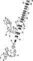
图1是本实用新型枢纽器较佳实施方式的立体分解图,所述枢纽器包括一第一干涉件。Fig. 1 is a three-dimensional exploded view of a preferred embodiment of the hinge device of the present invention, and the hinge device includes a first interference member.
图2是图1中的第一干涉件的立体放大图。FIG. 2 is an enlarged perspective view of the first interference element in FIG. 1 .
图3是图1的另一视角方向的立体分解图。FIG. 3 is an exploded perspective view of another viewing direction of FIG. 1 .
图4是图1的立体组装图。FIG. 4 is a perspective assembly view of FIG. 1 .
图5是图3的立体组装图。FIG. 5 is a perspective assembly view of FIG. 3 .
图6是图4的使用状态图。FIG. 6 is a diagram of the use state of FIG. 4 .
具体实施方式Detailed ways
请参照图1和图3,本实用新型枢纽器的较佳实施方式包括一转轴30、一第一连接件10、一第二连接件20、一第一止挡件40、一第二止挡件50、一第一干涉件60、一第二干涉件70、一包括若干个弹性片的弹片组80、一固定件90及分别安置于所述弹片组80的两端的两摩擦片100。第一连接件10及第二连接件20分别固定在一翻盖装置的上盖和底座。Please refer to Figure 1 and Figure 3, the preferred embodiment of the utility model hinge includes a
转轴30包括一扁平状的固定端32、一轴杆34及设置在固定端32与轴杆34之间的呈圆柱状的冠部36。轴杆34具有扁平的截面,其末端设有螺纹,以便于与固定件90相螺合。The rotating
第一连接件10包括一固定部12及自固定部12的一侧垂直延伸的连接部18。固定部12设有一贯通的非圆形固定孔14,用来固定转轴30的固定端32。连接部18设有若干固定孔180,以供螺钉或铆钉穿过,从而将第一连接件10与所述翻盖装置的底座相固定。The first connecting
第二连接件20包括一锁固部21及一自锁固部21的一侧延伸的弧形的枢接部22。锁固部21设有若干固定孔210,以供螺钉或铆钉穿过,从而将第二连接件20与所述翻盖装置的上盖相固定。枢接部22包括相对的一第一侧面220和一第二侧面222。枢接部22的末端设有一贯穿第一侧面220和第二侧面222的圆形枢转孔24及一固定孔26。所述枢转孔24可供转轴30的轴杆34穿设,从而第二连接件20可转动地套设于轴杆34。第二侧面222于该枢接部22的末端的边缘处凸伸成形一楔形的第一凸块29。所述第一侧面220凸设一楔形的第二凸块27,该第二凸块27的一端以一平滑的过渡面延伸至第一侧面220。The second connecting
第一止挡件40大致呈圆盘状,其边缘处开设有一弧形切口(未标号),从而于该弧形切口的两端分别形成一止挡面42。第一止挡件40设有一与转轴30的轴杆34的截面形状相对应的扁平状的轴孔44,用于固定套设所述转轴30的轴杆34。The
第二止挡件50的形状与第一止挡件40大致相同。第二止挡件50亦设有止挡面52和轴孔54,从而第二止挡件50可固定地套设于转轴30的轴杆34。The shape of the
请结合参照图2,第一干涉件60设有一可供转轴30的轴杆34穿设的通孔62,从而第一干涉件60可转动地套设于所述轴杆34。第一干涉件60的第一端面65凹陷成形有环绕通孔62的一第一凹陷部64及一第二凹陷部66。其中,第一凹陷部64靠近通孔62的边缘。第二凹陷部66与第一凹陷部64相对且靠近第一干涉件60的边缘。第一端面65凸设一止挡块67,第一干涉件60的边缘于邻近止挡块67处背向第一端面65沿轴向延伸一卡榫68。Please refer to FIG. 2 , the
第二干涉件70大致呈圆盘状,其边缘处开设有一弧形切口(未标号),从而于该切口的两端分别形成一抵挡面72。第二干涉件70的中部设有一与转轴30的轴杆34的截面形状相对应的扁平状的装配孔71,从而第二干涉件70可固定地套设于轴杆34。第二干涉件70面向第一干涉件60的端面凸设环绕装配孔71的一第一凸部74及一第二凸部76。其中,第一凸部74位于装配孔71的边缘,并对应卡合于第一干涉件60的第一凹陷部64。第二凸部76位于第一干涉件70的边缘,并对应卡合于第一干涉件60的第二凹陷部64。The second interfering
该弹片组80的每一弹性片均设有一供所述转轴30的轴杆34穿设的通孔82,从而所述弹片组80可转动地套设于所述轴杆34。Each elastic sheet of the elastic sheet set 80 is provided with a through
固定件90在本实施方式中为一螺母,其可以套设并螺锁于所述转轴30的轴杆34的螺纹上。In this embodiment, the fixing
每一摩擦片100设有一供所述转轴30的轴杆34穿设的扁平孔104,从而每一摩擦片100均固定套设于所述轴杆34。Each
请参照图4和5,组装时,转轴30的固定端32卡固于第一连接件10的固定孔14,从而转轴30与第一连接件10相互固定。转轴30的轴杆34依次穿过第一止挡件40的轴孔44、第二连接件20的枢转孔24、第二止挡件50的轴孔54、第一干涉件60的通孔62、第二干涉件70的装配孔71、其中一摩擦片100的扁平孔104、弹片组80的通孔82及另一摩擦片100的扁平孔104,然后将固定件90锁合于轴杆34的螺纹。所述固定件90用于防止第二连接件20、第一止挡件40、第二止挡件50、第一干涉件60、第二干涉件70、摩擦片100及弹片组80自轴杆34的末端滑落。Referring to FIGS. 4 and 5 , during assembly, the
在上述组装中,第二连接件20的第一侧面220及第二侧面222分别抵顶于第二止挡件50和第一止挡件40,且所述第一止挡件40抵顶于转轴30的冠部36。第一干涉件60的卡榫68固定于第二连接件20的固定孔26,从而与第二连接件20一起可相对于转轴30转动。第二干涉件70面向第一干涉件60的第一端面65,且第二干涉件70的第一凸部74及第二凸部76分别收容于第一干涉件60的第一凹部64及第二凹部66。此时,该翻盖装置的上盖闭合于该底座。In the above assembly, the
请结合参照图6,开启该翻盖装置时,旋转第二连接件20,带动第一干涉件60相对于转轴30转动,从而迫使第二干涉件70的第一凸部74及第二凸部76分别自第一干涉件60的第一凹部64及第二凹部66内滑出至抵接第一干涉件60的第一端面65,并而压迫弹片组80变形。此时,弹片组80的轴向变形力迫紧第一干涉件60及第二干涉件70而增加了第一干涉件60及第二干涉件70之间的摩擦阻滞力。因此,必须使用较大的外力旋转该第二连接件20,从而使所述上盖与所述底座处于闭合状态时不能轻易被开启。Please refer to FIG. 6 , when the flip device is opened, the second connecting
当该翻盖装置的上盖开启到预设角度时,第二连接件20的第一凸块29抵挡于第一止挡件40的其中一止挡面42;第二连接件20的第二凸块27止挡于第二止挡件50的其中一止挡面52;第一干涉件60的止挡块67也同时抵挡于第二干涉件70的其中一抵挡面72,从而使第二连接件20无法继续转动,进而限制了该翻盖装置的旋转角度,防止了该翻盖装置因不当外力而翻转过度。When the upper cover of the flip device is opened to a preset angle, the
Claims (10)
Translated fromChinesePriority Applications (2)
| Application Number | Priority Date | Filing Date | Title |
|---|---|---|---|
| CN2009203072805UCN201513461U (en) | 2009-08-03 | 2009-08-03 | hub |
| US12/554,970US20110023271A1 (en) | 2009-08-03 | 2009-09-07 | Hinge |
Applications Claiming Priority (1)
| Application Number | Priority Date | Filing Date | Title |
|---|---|---|---|
| CN2009203072805UCN201513461U (en) | 2009-08-03 | 2009-08-03 | hub |
Publications (1)
| Publication Number | Publication Date |
|---|---|
| CN201513461Utrue CN201513461U (en) | 2010-06-23 |
Family
ID=42484869
Family Applications (1)
| Application Number | Title | Priority Date | Filing Date |
|---|---|---|---|
| CN2009203072805UExpired - Fee RelatedCN201513461U (en) | 2009-08-03 | 2009-08-03 | hub |
Country Status (2)
| Country | Link |
|---|---|
| US (1) | US20110023271A1 (en) |
| CN (1) | CN201513461U (en) |
Cited By (4)
| Publication number | Priority date | Publication date | Assignee | Title |
|---|---|---|---|---|
| CN102062144A (en)* | 2010-11-11 | 2011-05-18 | 广州市建筑机械施工有限公司 | Hinge |
| CN102865290A (en)* | 2012-09-05 | 2013-01-09 | 北京泛华恒兴科技有限公司 | Component connection rotary device |
| CN103197729A (en)* | 2012-01-05 | 2013-07-10 | 宏碁股份有限公司 | Electronic device and its connecting mechanism |
| CN114810802A (en)* | 2022-04-21 | 2022-07-29 | 荣耀终端有限公司 | Spindle assembly and foldable device |
Families Citing this family (7)
| Publication number | Priority date | Publication date | Assignee | Title |
|---|---|---|---|---|
| CN201420797Y (en)* | 2009-04-28 | 2010-03-10 | 康准电子科技(昆山)有限公司 | hub |
| CN101876337A (en)* | 2009-04-28 | 2010-11-03 | 康准电子科技(昆山)有限公司 | hub |
| CN201439798U (en)* | 2009-05-27 | 2010-04-21 | 康准电子科技(昆山)有限公司 | Hinge |
| US8544151B2 (en)* | 2011-11-22 | 2013-10-01 | Lang-Mekra North America, Llc | Engaging surfaces arrangement for a pivoting detent joint |
| US9309636B2 (en)* | 2012-07-27 | 2016-04-12 | Duncan C. WYLLIE | Rockfall barrier |
| TWI663500B (en)* | 2018-03-02 | 2019-06-21 | 宏碁股份有限公司 | Hinge structure and electronic device |
| TWI801320B (en)* | 2022-09-27 | 2023-05-01 | 和碩聯合科技股份有限公司 | Hinge device |
Family Cites Families (12)
| Publication number | Priority date | Publication date | Assignee | Title |
|---|---|---|---|---|
| US6108868A (en)* | 1998-03-30 | 2000-08-29 | Lin; Davys | Positioning hinge having a cam block |
| KR100703160B1 (en)* | 2001-02-19 | 2007-04-05 | 삼성전자주식회사 | Display device |
| US6671928B2 (en)* | 2001-05-23 | 2004-01-06 | Kuo-Cheng Huang | Hinge assembly for monitor |
| WO2003062970A1 (en)* | 2001-12-24 | 2003-07-31 | Lg Electronics Inc. | Hinge assembly for flat panel display appliance |
| US6813813B2 (en)* | 2003-01-06 | 2004-11-09 | Shin Zu Shing Co., Ltd. | Collapsible hinge bracket for a laptop computer |
| US6779234B1 (en)* | 2003-04-14 | 2004-08-24 | Shin Zu Shing Co., Ltd. | Elastic hinge for a notebook computer |
| US6920670B2 (en)* | 2003-12-16 | 2005-07-26 | Tai Wen Hao | Hinge structure |
| US7222396B2 (en)* | 2005-03-09 | 2007-05-29 | Shin Zu Shing Co., Ltd | Robust hinge |
| US7513011B2 (en)* | 2005-12-29 | 2009-04-07 | Shin Zu Shing Co., Ltd. | Hinge with multiple torsion springs |
| US20070199179A1 (en)* | 2006-02-28 | 2007-08-30 | Ting-Hsien Wang | Hinge with less noise |
| US20090172916A1 (en)* | 2008-01-04 | 2009-07-09 | Jr-Jiun Chern | Hinge Assembly |
| TW200934962A (en)* | 2008-02-05 | 2009-08-16 | Leohab Entpr Co Ltd | Pivot with increased load |
- 2009
- 2009-08-03CNCN2009203072805Upatent/CN201513461U/ennot_activeExpired - Fee Related
- 2009-09-07USUS12/554,970patent/US20110023271A1/ennot_activeAbandoned
Cited By (7)
| Publication number | Priority date | Publication date | Assignee | Title |
|---|---|---|---|---|
| CN102062144A (en)* | 2010-11-11 | 2011-05-18 | 广州市建筑机械施工有限公司 | Hinge |
| CN102062144B (en)* | 2010-11-11 | 2012-12-05 | 广州机施建设集团有限公司 | Hinge |
| CN103197729A (en)* | 2012-01-05 | 2013-07-10 | 宏碁股份有限公司 | Electronic device and its connecting mechanism |
| CN103197729B (en)* | 2012-01-05 | 2016-09-21 | 宏碁股份有限公司 | Electronic device and its connecting mechanism |
| CN102865290A (en)* | 2012-09-05 | 2013-01-09 | 北京泛华恒兴科技有限公司 | Component connection rotary device |
| CN102865290B (en)* | 2012-09-05 | 2016-04-27 | 北京泛华恒兴科技有限公司 | A kind of component connection rotary device |
| CN114810802A (en)* | 2022-04-21 | 2022-07-29 | 荣耀终端有限公司 | Spindle assembly and foldable device |
Also Published As
| Publication number | Publication date |
|---|---|
| US20110023271A1 (en) | 2011-02-03 |
Similar Documents
| Publication | Publication Date | Title |
|---|---|---|
| CN201513461U (en) | hub | |
| CN201496396U (en) | hub | |
| CN103291737B (en) | Card lock double axis hub | |
| US7526835B2 (en) | Stable hinge | |
| CN101666352B (en) | Hinge structure | |
| CN201246405Y (en) | Hubs and Interfering Components | |
| CN101614238B (en) | Hinge structure | |
| CN201547125U (en) | hub | |
| CN103307094B (en) | Card lock double axis hub | |
| US20090235489A1 (en) | Sheath Type Rotating Axel Structure with Automatic Locking Mechanism | |
| CN101684837A (en) | Hinge structure | |
| CN101614237A (en) | Hinge structure | |
| CN101105198A (en) | Hinge mechanism | |
| US20090158556A1 (en) | Covered rotation shaft structure having auto locking function | |
| US20100269296A1 (en) | Hinge | |
| US20110088219A1 (en) | Hinge assembly | |
| TWI463078B (en) | Card lathe biaxial hub | |
| CN201391539Y (en) | hub | |
| TWI490420B (en) | Rotary stop type biaxial hub | |
| US20110047755A1 (en) | Hinge | |
| TWI486530B (en) | Card lathe biaxial hub | |
| CN102235419A (en) | Pivot device | |
| CN201696463U (en) | Concave-convex wheel structure of pivot device | |
| CN201277255Y (en) | Pivotal device | |
| JP4739429B2 (en) | 2-axis hinge |
Legal Events
| Date | Code | Title | Description |
|---|---|---|---|
| C14 | Grant of patent or utility model | ||
| GR01 | Patent grant | ||
| C17 | Cessation of patent right | ||
| CF01 | Termination of patent right due to non-payment of annual fee | Granted publication date:20100623 Termination date:20110803 |