CN201508161U - Spatial filtering holographic interferometer - Google Patents
Spatial filtering holographic interferometerDownload PDFInfo
- Publication number
- CN201508161U CN201508161UCN2009201122566UCN200920112256UCN201508161UCN 201508161 UCN201508161 UCN 201508161UCN 2009201122566 UCN2009201122566 UCN 2009201122566UCN 200920112256 UCN200920112256 UCN 200920112256UCN 201508161 UCN201508161 UCN 201508161U
- Authority
- CN
- China
- Prior art keywords
- slit
- plate
- light
- lens
- holographic
- Prior art date
- Legal status (The legal status is an assumption and is not a legal conclusion. Google has not performed a legal analysis and makes no representation as to the accuracy of the status listed.)
- Expired - Fee Related
Links
- 238000001914filtrationMethods0.000titleclaimsabstractdescription12
- 230000003287optical effectEffects0.000claimsabstractdescription12
- 230000001427coherent effectEffects0.000claimsabstractdescription8
- 229910021532CalciteInorganic materials0.000claimsdescription11
- 238000000034methodMethods0.000abstractdescription5
- 230000001105regulatory effectEffects0.000abstract1
- 239000013078crystalSubstances0.000description5
- 238000005286illuminationMethods0.000description3
- 230000002452interceptive effectEffects0.000description3
- 238000001228spectrumMethods0.000description3
- 230000007812deficiencyEffects0.000description2
- 238000010586diagramMethods0.000description2
- 238000005516engineering processMethods0.000description2
- 238000005259measurementMethods0.000description2
- 230000010287polarizationEffects0.000description2
- 230000000694effectsEffects0.000description1
- 230000005686electrostatic fieldEffects0.000description1
- GQYHUHYESMUTHG-UHFFFAOYSA-Nlithium niobateChemical compound[Li+].[O-][Nb](=O)=OGQYHUHYESMUTHG-UHFFFAOYSA-N0.000description1
- 238000004519manufacturing processMethods0.000description1
- 238000000691measurement methodMethods0.000description1
- 230000003068static effectEffects0.000description1
Images
Landscapes
- Instruments For Measurement Of Length By Optical Means (AREA)
Abstract
Description
Translated fromChinese技术领域:Technical field:
本实用新型涉及领域为采用光学测量方法为其特征的仪器,特别是一种空间滤波全息干涉仪。这种干涉仪主要用于测量光路中的微小光程变化。The utility model relates to the field of an instrument characterized by the use of an optical measurement method, in particular to a spatial filtering holographic interferometer. This interferometer is mainly used to measure small optical path changes in the optical path.
背景技术:Background technique:
经典的干涉仪一般可以分为双光束干涉仪和多光束干涉仪,等厚或等倾干涉仪,它们的优点是结构简单、使用方便,但它们对元件的精度要求高并且需要在稳定的操作环境中进行,在制造过程和实际应用上有所限制。由于全息干涉仪对光学零部件的精密度要求低。可对表面形变进行记录并可实时进行测量。因此一些全息干涉仪被提出来。其中包括调制一条边缝位相的全息三缝干涉仪和调制中缝位相的全息三缝干涉仪。尽管构成这些干涉仪的在先技术有一定的优点,但是仍然存在一些不足:Classical interferometers can generally be divided into two-beam interferometers and multi-beam interferometers, equal-thickness or equal-tilt interferometers. Their advantages are simple structure and easy use, but they require high precision of components and require stable operation. environment, there are limitations in the manufacturing process and practical applications. Because the holographic interferometer has low requirements on the precision of optical components. Surface deformations can be recorded and measured in real time. Therefore some holographic interferometers have been proposed. These include a holographic three-slit interferometer that modulates the phase of one side slit and a holographic three-slit interferometer that modulates the phase of the middle slit. Despite the advantages of the prior art that makes up these interferometers, there are still some deficiencies:
(1)、此两种方法对再现照明光的要求高,如果再现照明光相对于原参考光有个微小的偏移,再现光的光场分布将与原双缝衍射光场有较大差别,这时再现的两边缝波前与中缝的衍射波前不再相符,两者也不能形成干涉图。此时可以认为干涉图消失,装置不能工作。(1) These two methods have high requirements for the reproduced illumination light. If the reproduced illumination light has a slight offset relative to the original reference light, the light field distribution of the reproduced light will be quite different from the original double-slit diffraction light field. , at this time, the reproduced wavefronts on both sides of the slit are no longer consistent with the diffracted wavefronts of the middle slit, and the two cannot form an interferogram. At this time, it can be considered that the interference pattern disappears and the device cannot work.
(2)、精度不高,未能排除干扰光。(2) The accuracy is not high, and the interference light cannot be excluded.
实用新型内容Utility model content
本实用新型要解决的问题在于克服了上述在先技术的不足,提供了一种基于空间滤波的全息干涉仪,它保证了重构波前的相位分配而不受激光束较小的方向漂移和细微的外部震动的影响。且具有工作稳定性好,结构简单,测量精度高等优点。The problem to be solved by the utility model is to overcome the deficiencies of the above-mentioned prior art, and provide a holographic interferometer based on spatial filtering, which ensures the phase distribution of the reconstructed wavefront without being affected by the small direction drift and The influence of subtle external vibrations. And it has the advantages of good working stability, simple structure and high measurement accuracy.
本实用新型的基本构思是:The basic idea of the utility model is:
本实用新型提供一种利用空间滤波和全息技术的干涉仪。它包括光源及沿产生线偏振光的光源的光线方向依次设置的半波片、方解石片、第二半波片、相位物体、相位补偿器、狭缝板、全息干板、透镜、空间滤波器、第二透镜、面阵光电传感器、显示器所构成;第二半波片平行于相位物体和相位补偿器放置;狭缝板带有可调狭缝和固定狭缝;空间滤波器孔径可调。从方解石片出射的两束相邻的平行光,一束光经过相位物体后通过相位补偿器到达缝S1,另一束光经过平行于相位物体和相位补偿器放置的第二半波片到达固定缝S2。通过缝S1和缝S2衍射的光形成一系列干涉条纹并记录在全息干板上。调整可移动缝到S3的位置,并保持缝S3到缝S2的距离与缝S1到缝S2的距离相等。使通过缝S3和缝S2的衍射光形成一系列的干涉条纹并记录在同一个全息干板上,经处理和复位全息干板后,通过固定缝S2的衍射光作为再现光照射全息干板,重构出缝S1和缝S3的衍射波前。同时经过固定缝S2的衍射光直接照射全息干板,与其它两缝的衍射波构成三波面衍射波前,在透镜后焦面上形成三波面衍射频谱,利用空间滤波器滤去干扰光,经过第二透镜的会聚进入面阵光电传感器,最后由显示器显示出结果。The utility model provides an interferometer utilizing space filtering and holographic technology. It includes a light source and a half-wave plate, a calcite plate, a second half-wave plate, a phase object, a phase compensator, a slit plate, a holographic dry plate, a lens, and a spatial filter that are sequentially arranged along the light direction of the light source that produces linearly polarized light. , a second lens, an area array photoelectric sensor, and a display; the second half-wave plate is placed parallel to the phase object and the phase compensator; the slit plate has adjustable slits and fixed slits; the spatial filter aperture is adjustable. Two adjacent beams of parallel light emitted from the calcite sheet, one beam passes through the phase object and then passes through the phase compensator to reach the slit S1 , and the other beam passes through the second half-wave plate placed parallel to the phase object and the phase compensator Fixing seam S2 . Light diffracted by slit S1 and slit S2 forms a series of interference fringes and is recorded on the holographic dry plate. Adjust the position of the movable seam toS3 and keep the distance from seamS3 to seamS2 equal to the distance from seamS1 to seamS2 . The diffracted light passing through the slitS3 andS2 forms a series of interference fringes and records them on the same holographic dry plate. After processing and resetting the holographic dry plate, the diffracted light passing through the fixed slitS2 is used as the reproduction light to irradiate the holographic Dry the plate and reconstruct the diffracted wavefronts of slit S1 and slit S3 . At the same time, the diffracted light passing through the fixed slitS2 directly irradiates the holographic dry plate, forms a three-wavefront diffraction wavefront with the diffracted waves of the other two slits, and forms a three-wavefront diffraction spectrum on the rear focal plane of the lens, and uses a spatial filter to filter out the interfering light. After the convergence of the second lens, it enters the area array photoelectric sensor, and finally the result is displayed on the display.
本实用新型的技术解决方案如下:The technical solution of the utility model is as follows:
本实用新型提供一种利用空间滤波和全息技术的干涉仪。它包括相干光源、半波片、方解石片、第二半波片、相位物体、相位补偿器、狭缝板、全息干板、透镜、空间滤波器、透镜、面阵光电传感器、显示器所构成;半波片平行于相位物体和相位补偿器放置;狭缝板带有可调狭缝和固定狭缝;空间滤波器为孔径可调滤波器。相干光源出射光束方向上依次置有半波片、方解石片、半波片、相位物体、相位补偿器、狭缝板、全息干板、透镜、空间滤波器、透镜、面阵光电传感器、显示器。The utility model provides an interferometer utilizing space filtering and holographic technology. It consists of a coherent light source, a half-wave plate, a calcite plate, a second half-wave plate, a phase object, a phase compensator, a slit plate, a holographic dry plate, a lens, a spatial filter, a lens, an area array photoelectric sensor, and a display; The half-wave plate is placed parallel to the phase object and the phase compensator; the slit plate has adjustable slits and fixed slits; the spatial filter is an aperture-tunable filter. A half-wave plate, a calcite plate, a half-wave plate, a phase object, a phase compensator, a slit plate, a holographic dry plate, a lens, a spatial filter, a lens, an area array photoelectric sensor, and a display are sequentially arranged in the direction of the beam emitted by the coherent light source.
上述实现空间滤波全息干涉仪的方解石片是光轴平行其表面的光学部件。The above-mentioned calcite plate for realizing the spatial filtering holographic interferometer is an optical component whose optical axis is parallel to its surface.
本实用新型提供的一种实现空间滤波全息干涉仪如上所述结构,工作过程为:相干光源出射的相干光束经过半波片,半波片可对从方解石片出射的两相邻平行光的强度进行调制,出射的两平行光一束经过相位物体,再经过相位补偿器到达可移动缝S1,而另一束光经过半波片后到达固定缝S2,半波片并不改变原光束的偏振方向。通过缝S1和缝S2的两衍射光经过干涉形成一系列干涉条纹并记录在全息干板上,调整可移动缝到缝S3的位置,并保持缝S3到缝S2的距离与缝S1到缝S2距离相等。使通过缝S3和缝S2的衍射光再一次干涉形成一系列的干涉条纹并记录在同一个全息干板上,经处理和复位全息干板后,让通过固定缝S2的衍射光作为再现光照射全息干板,重构出缝S1和缝S3的衍射波前。同时经过固定缝S2的衍射光直接照射全息干板,与其它两缝的衍射波构成三波面衍射波前。在透镜的后焦面上形成三波面衍射频谱,利用空间滤波器滤去干扰光,经过透镜的会聚进入面阵光电传感器,最后由显示器显示出结果。The utility model provides a space filter holographic interferometer with the above-mentioned structure. The working process is: the coherent light beam emitted by the coherent light source passes through the half-wave plate, and the half-wave plate can control the intensity of two adjacent parallel lights emitted from the calcite plate. Modulation is carried out. One beam of the outgoing parallel light passes through the phase object, then passes through the phase compensator to reach the movable slit S1 , and the other beam passes through the half-wave plate and then reaches the fixed slit S2 . The half-wave plate does not change the original beam Polarization direction. The two diffracted lights passing through slit S1 and slit S2 are interfered to form a series of interference fringes and recorded on the holographic dry plate, adjust the position of the movable slit to slit S3 , and keep the distance from slit S3 to slit S2 equal to The distance from seam S1 to seam S2 is equal. Let the diffracted light passing through the slitS3 andS2 interfere again to form a series of interference fringes and record them on the same holographic dry plate. After processing and resetting the holographic dry plate, let the diffracted light passing through the fixed slitS2 become The reconstructed light irradiates the holographic dry plate, and reconstructs the diffracted wavefronts of slit S1 and slit S3 . At the same time, the diffracted light passing through the fixed slit S2 directly irradiates the holographic dry plate, and forms a three-wavefront diffraction wavefront with the diffracted waves of the other two slits. The three-wavefront diffraction spectrum is formed on the rear focal plane of the lens, and the interfering light is filtered out by a spatial filter, and then converged by the lens into the area array photoelectric sensor, and finally the result is displayed on the display.
与在先技术相比,本实用新型的优点:Compared with the prior art, the utility model has the following advantages:
1)结构简单,操作方便且具有很好的稳定性和较高测量精度。1) The structure is simple, the operation is convenient, and it has good stability and high measurement accuracy.
2)用两个相邻的缝来确定目标光场、参考光以及再现照明光的相对位置,并通过滤波器过滤由设计引起的干扰光。使再现光和记录的光保持一致,干涉图更易于观察。2) Use two adjacent slits to determine the relative positions of the target light field, reference light and reproduced illumination light, and filter the interference light caused by the design through a filter. By aligning the reproduced light with the recorded light, the interferogram is easier to observe.
附图说明:Description of drawings:
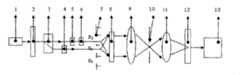
图1为本实用新型实施例的系统结构示意图。Fig. 1 is a schematic diagram of the system structure of the embodiment of the utility model.
具体实施方式Detailed ways
以下结合附图说明对本实用新型的实施例作进一步详细描述,但本实施例并不只用于限制本实用新型,凡是采用本实用新型的相似结构及其相似变化,均应列入本实用新型的保护范围。Below in conjunction with accompanying drawing description, the embodiment of the utility model is further described in detail, but the embodiment is not only used to limit the utility model, any similar structures and similar changes of the utility model should be included in the utility model protected range.
本实用新型实施例所提供的一种实现空间滤波全息干涉仪,图1为本实用新型实施例示意图。一种空间滤波全息干涉仪,其特征在于系统由相干光源1、半波片2、方解石片3、半波片4、相位物体5、相位补偿器6、狭缝板7、全息干板8、透镜9、空间滤波器10、透镜11、面阵光电传感器12、显示器13所构成;半波片4平行于相位物体5和相位补偿器6放置;狭缝板7带有可调狭缝和固定狭缝;空间滤波器10为孔径可调滤波器。相干光源发射部件1出射光束方向上依次置有半波片2、方解石片3、半波片4、相位物体5、相位补偿器6、狭缝板7、全息干板8、透镜9、空间滤波器10、透镜11、面阵光电传感器12、显示器13。半波片4则平行于相位物体5和相位补偿器6放置。半波片2可对从方解石片3出射的两相邻平行光的强度进行调制,出射的两平行光一束经过相位物体5,再经过相位补偿器6到达可移动缝S1,而另一束光经过半波片4后到达固定缝S2,半波片4并不改变原光束的偏振方向。通过缝S1和缝S2的两衍射光形成一系列干涉条纹并记录在全息干板8上,调整可移动缝到缝S3的位置,并保持缝S3到缝S2的距离与缝S1到缝S2距离相等。通过缝S3和缝S2的衍射光形成一系列的干涉条纹并记录在同一个全息干板8上,经处理和复位全息干板8后,让通过固定缝S2的衍射光作为再现光照射全息干板8,重构出缝S1和缝S3的衍射波前。同时经过固定缝S2的衍射光直接照射全息干板8,与其它两缝的衍射波构成三波面衍射波前。在透镜9的后焦面上形成三波面衍射频谱,利用空间滤波器10滤去干扰光,经过透镜11的会聚进入面阵光电传感器12被扫描接收,最后由显示器显示出结果。The embodiment of the utility model provides a holographic interferometer for realizing spatial filtering, and Fig. 1 is a schematic diagram of the embodiment of the utility model. A spatial filtering holographic interferometer, characterized in that the system consists of a
采用上述方法,我们检测到了铌酸锂晶体的电光效应。样品呈长方形,其大小为5mm*5mm*40mm且分别对应于X,Y,Z方向。光轴平行于X轴。激光束照射中缝并沿着Z轴通过晶体。光场的电向量平行于Y轴。外部的静电场沿着Y轴加于晶体上。可以观察到光强度随着外部静态电压的变化而变化。这说明晶体的折射率随着外部电压的变化而变化。我们测量了晶体的折射率变化Δn值。Using the method described above, we detected the electro-optic effect of lithium niobate crystals. The sample is rectangular, and its size is 5mm*5mm*40mm and corresponds to the X, Y, and Z directions respectively. The optical axis is parallel to the X axis. The laser beam illuminates the central slit and passes through the crystal along the Z axis. The electric vector of the light field is parallel to the Y axis. An external electrostatic field is applied to the crystal along the Y axis. It can be observed that the light intensity varies with the external static voltage. This shows that the refractive index of the crystal changes with the external voltage. We measured the refractive index change Δn value of the crystal.
Claims (2)
Translated fromChinesePriority Applications (1)
| Application Number | Priority Date | Filing Date | Title |
|---|---|---|---|
| CN2009201122566UCN201508161U (en) | 2009-01-08 | 2009-01-08 | Spatial filtering holographic interferometer |
Applications Claiming Priority (1)
| Application Number | Priority Date | Filing Date | Title |
|---|---|---|---|
| CN2009201122566UCN201508161U (en) | 2009-01-08 | 2009-01-08 | Spatial filtering holographic interferometer |
Publications (1)
| Publication Number | Publication Date |
|---|---|
| CN201508161Utrue CN201508161U (en) | 2010-06-16 |
Family
ID=42469288
Family Applications (1)
| Application Number | Title | Priority Date | Filing Date |
|---|---|---|---|
| CN2009201122566UExpired - Fee RelatedCN201508161U (en) | 2009-01-08 | 2009-01-08 | Spatial filtering holographic interferometer |
Country Status (1)
| Country | Link |
|---|---|
| CN (1) | CN201508161U (en) |
Cited By (7)
| Publication number | Priority date | Publication date | Assignee | Title |
|---|---|---|---|---|
| CN103097857A (en)* | 2010-09-07 | 2013-05-08 | 大日本印刷株式会社 | Scanner device and device for measuring three-dimensional shape of object |
| CN107305289A (en)* | 2016-04-20 | 2017-10-31 | 中国科学院化学研究所 | A kind of optical system and its method of work for microcell spatial coherence pattern |
| CN108231094A (en)* | 2013-01-07 | 2018-06-29 | 阿森蒂亚影像有限公司 | Use the optical guidance system and method for the signal correction sensor being distinguished from each other |
| CN111900597A (en)* | 2020-08-17 | 2020-11-06 | 武汉金顿激光科技有限公司 | A method and system for controlling parameters of planar multi-beam laser |
| CN112969899A (en)* | 2018-10-30 | 2021-06-15 | Rd 辛纳基有限公司 | System and method for holographic interferometry |
| US11092662B2 (en) | 2012-01-03 | 2021-08-17 | Ascentia Imaging, Inc. | Optical guidance systems and methods using mutually distinct signal-modifying sensors |
| US11892292B2 (en) | 2017-06-06 | 2024-02-06 | RD Synergy Ltd. | Methods and systems of holographic interferometry |
- 2009
- 2009-01-08CNCN2009201122566Upatent/CN201508161U/ennot_activeExpired - Fee Related
Cited By (12)
| Publication number | Priority date | Publication date | Assignee | Title |
|---|---|---|---|---|
| CN103097857A (en)* | 2010-09-07 | 2013-05-08 | 大日本印刷株式会社 | Scanner device and device for measuring three-dimensional shape of object |
| CN103097857B (en)* | 2010-09-07 | 2014-12-24 | 大日本印刷株式会社 | Scanner device and three-dimensional shape measuring device of object |
| US11092662B2 (en) | 2012-01-03 | 2021-08-17 | Ascentia Imaging, Inc. | Optical guidance systems and methods using mutually distinct signal-modifying sensors |
| US12130642B2 (en) | 2012-01-03 | 2024-10-29 | Ascentia Imaging, Inc. | Optical guidance systems and methods using mutually distinct signal-modifying sensors |
| CN108231094A (en)* | 2013-01-07 | 2018-06-29 | 阿森蒂亚影像有限公司 | Use the optical guidance system and method for the signal correction sensor being distinguished from each other |
| CN107305289A (en)* | 2016-04-20 | 2017-10-31 | 中国科学院化学研究所 | A kind of optical system and its method of work for microcell spatial coherence pattern |
| CN107305289B (en)* | 2016-04-20 | 2019-10-01 | 中国科学院化学研究所 | A kind of optical system and its working method for microcell spatial coherence pattern |
| US11892292B2 (en) | 2017-06-06 | 2024-02-06 | RD Synergy Ltd. | Methods and systems of holographic interferometry |
| CN112969899A (en)* | 2018-10-30 | 2021-06-15 | Rd 辛纳基有限公司 | System and method for holographic interferometry |
| CN112969899B (en)* | 2018-10-30 | 2023-03-10 | Rd 辛纳基有限公司 | System and method for holographic interferometry |
| US11719531B2 (en) | 2018-10-30 | 2023-08-08 | RD Synergy Ltd. | Methods and systems of holographic interferometry |
| CN111900597A (en)* | 2020-08-17 | 2020-11-06 | 武汉金顿激光科技有限公司 | A method and system for controlling parameters of planar multi-beam laser |
Similar Documents
| Publication | Publication Date | Title |
|---|---|---|
| CN201508161U (en) | Spatial filtering holographic interferometer | |
| CN102261985B (en) | Optical system wave aberration calibration apparatus and calibration method of using apparatus to test error | |
| CN101451890B (en) | A three-light wave transverse shearing interference device and method for extracting differential phase | |
| JP7231946B2 (en) | SURFACE PROFILE MEASURING DEVICE AND SURFACE PROFILE MEASURING METHOD | |
| Brock et al. | Dynamic interferometry | |
| CN107462149B (en) | A phase shift interferometry system and its wave plate phase shift method | |
| CN203365108U (en) | Common-path interference measurement device for generated optical aberration of liquid-crystal spatial light modulator | |
| CN104713494B (en) | The dual wavelength tuning interference testing device and method of Fourier transformation phase shift calibration | |
| CN101788344B (en) | Instantaneous phase-shift transverse shear interferometer | |
| CN104006763A (en) | Digital holographic three-dimensional appearance detecting device based on multiple wavelengths | |
| CN105092056B (en) | Digital phase-shifting technique point-diffraction interferometer and optical system wavefront aberration measuring method | |
| Colomb et al. | Jones vector imaging by use of digital holography: simulation and experimentation | |
| CN111912603B (en) | Method and system for calibrating phase type spatial light modulator based on optical differentiator | |
| CN107490947B (en) | Dual-channel common-path off-axis polarization holographic imaging system and method | |
| CN110927116B (en) | Method, device and system for measuring mark structure | |
| CN201795864U (en) | A Transient Shearing Interferometer with Instantaneous Phase Shift | |
| CN107101722A (en) | A kind of broadband linear polarization imaging method based on Mach Zehnder interferometer | |
| CN107421641B (en) | A kind of broadband full polarization imaging device based on Mach Zehnder interferometer | |
| Islas et al. | Development of a dynamic interferometer using recycled components based on polarization phase shifting techniques | |
| CN103196387B (en) | Cylindrical surface type detection system and method | |
| CN104730001A (en) | High-time-resolution high-precision elliptically-polarized measurement device and high-time-resolution high-precision elliptically-polarized measurement method | |
| Gesualdi et al. | Wave optics analysis by phase-shifting real-time holographic interferometry | |
| CN114812432A (en) | Rapid phase acquisition system and method applied to laser interference morphology detection | |
| WO2005049840A2 (en) | Process and apparatus for measuring the three-dimensional shape of an object | |
| CN114323580A (en) | A kind of multi-azimuth synchronous phase shift transverse shear interference device and measurement method |
Legal Events
| Date | Code | Title | Description |
|---|---|---|---|
| C14 | Grant of patent or utility model | ||
| GR01 | Patent grant | ||
| C17 | Cessation of patent right | ||
| CF01 | Termination of patent right due to non-payment of annual fee | Granted publication date:20100616 Termination date:20110108 |