CN201496619U - Double-chamber automobile series valve - Google Patents
Double-chamber automobile series valveDownload PDFInfo
- Publication number
- CN201496619U CN201496619UCN2009202275963UCN200920227596UCN201496619UCN 201496619 UCN201496619 UCN 201496619UCN 2009202275963 UCN2009202275963 UCN 2009202275963UCN 200920227596 UCN200920227596 UCN 200920227596UCN 201496619 UCN201496619 UCN 201496619U
- Authority
- CN
- China
- Prior art keywords
- valve body
- valve
- double
- ejector rod
- loop
- Prior art date
- Legal status (The legal status is an assumption and is not a legal conclusion. Google has not performed a legal analysis and makes no representation as to the accuracy of the status listed.)
- Expired - Fee Related
Links
- 230000000694effectsEffects0.000abstractdescription2
- 238000005273aerationMethods0.000abstract1
- 238000010586diagramMethods0.000description2
- 230000009286beneficial effectEffects0.000description1
- 238000009434installationMethods0.000description1
- 230000007257malfunctionEffects0.000description1
- 238000000034methodMethods0.000description1
Images
Classifications
- Y—GENERAL TAGGING OF NEW TECHNOLOGICAL DEVELOPMENTS; GENERAL TAGGING OF CROSS-SECTIONAL TECHNOLOGIES SPANNING OVER SEVERAL SECTIONS OF THE IPC; TECHNICAL SUBJECTS COVERED BY FORMER USPC CROSS-REFERENCE ART COLLECTIONS [XRACs] AND DIGESTS
- Y02—TECHNOLOGIES OR APPLICATIONS FOR MITIGATION OR ADAPTATION AGAINST CLIMATE CHANGE
- Y02T—CLIMATE CHANGE MITIGATION TECHNOLOGIES RELATED TO TRANSPORTATION
- Y02T10/00—Road transport of goods or passengers
- Y02T10/10—Internal combustion engine [ICE] based vehicles
- Y02T10/12—Improving ICE efficiencies
Landscapes
- Valves And Accessory Devices For Braking Systems (AREA)
Abstract
Description
Translated fromChinese技术领域:Technical field:
本实用新型涉及一种串联阀,具体涉及一种双腔汽车串联阀,属汽车零部件技术领域。The utility model relates to a tandem valve, in particular to a double-cavity automobile tandem valve, which belongs to the technical field of auto parts.
背景技术:Background technique:
汽车的制动是将汽缸内的压缩空气通过汽车气制动阀输送到前后快放阀,然后再到各个车轮制动机构内而达到汽车制动目的的。目前的汽车多采用单管路断气制动,它的不足之处在于单管路断气制动仅靠一条主管路实现充气和断气制动,当汽车连续制动时,主管路就无法继续向储气筒充气,造成储气筒气压连续下降,而降低制动强度,甚至制动功能消失。也有采用紧急继动阀来实现双管路制动,即一条充气管路,一条制动管路,但当充气管路损坏而无法向储气筒充气,或制动管路漏气、损坏,则起不到双重保险的作用。The brake of the car is to send the compressed air in the cylinder to the front and rear quick-release valves through the car air brake valve, and then to each wheel brake mechanism to achieve the purpose of car braking. Most of the current automobiles use single-pipeline air-cut brakes. Its shortcoming is that the single-pipeline air-break brakes only rely on one main pipe to realize inflation and air-break braking. When the car brakes continuously, the main pipe cannot continue The air cylinder is inflated, causing the air pressure of the air cylinder to drop continuously, reducing the braking strength, and even the braking function disappears. There are also emergency relay valves used to achieve dual-pipeline braking, that is, one inflation pipeline and one brake pipeline. Can not achieve the effect of double insurance.
发明内容:Invention content:
本实用新型的目的在于,提供一种当充气管路或制动管路出现损坏故障失灵时,能应急制动的双腔汽车串联阀。The purpose of the utility model is to provide a dual-cavity automotive series valve capable of emergency braking when the inflation pipeline or the brake pipeline is damaged and malfunctions.
本实用新型是通过如下技术方案来实现上述目的的:The utility model realizes above-mentioned object through following technical scheme:
一种双腔汽车串联阀,它由脚踏板、顶杆、安装座、上阀体、下阀体、顶杆座、平衡活塞、复位弹簧构成,其特征在于:安装座的上方装有脚踏板,安装座的下方装有上阀体,上阀体的下方装有下阀体,上阀体的内部上方装有顶杆座,并经顶杆与脚踏板连接;顶杆座的下方装有平衡活塞,平衡活塞下装有复位弹簧;所述的上阀体和下阀体上分别制有上进气口、上输出口和下进气口、下输出口。A double-cavity automobile series valve, which is composed of a pedal, a push rod, a mounting seat, an upper valve body, a lower valve body, a push rod seat, a balance piston, and a return spring, and is characterized in that: a foot is installed above the mounting seat Pedal, the upper valve body is installed under the mounting seat, the lower valve body is installed under the upper valve body, and the ejector seat is installed above the interior of the upper valve body, and is connected with the pedal through the ejector rod; A balance piston is installed below, and a return spring is installed under the balance piston; the upper air inlet, upper output port, lower air inlet, and lower output port are respectively formed on the upper valve body and the lower valve body.
本实用新型与现有技术相比的有益效果在于:The utility model has the beneficial effects compared with the prior art in that:
该双腔汽车串联阀当第一回路失效时,阀体内的阀门总成能强行推开活塞向下移动,关闭排气阀门后,再打开进气阀门,使第二回路正常工作。而当第二回路失效时,不影响第一回路正常工作,起到了制动双重保险的作用。When the first circuit fails, the valve assembly in the valve body can forcibly push the piston to move downward, close the exhaust valve, and then open the intake valve to make the second circuit work normally. And when the second circuit fails, it does not affect the normal operation of the first circuit, and plays the role of double insurance of braking.
附图说明:Description of drawings:
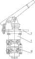
图1为双腔汽车串联阀的外形结构示意图;Fig. 1 is a schematic diagram of the shape and structure of a dual-cavity automobile tandem valve;
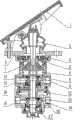
图2为双腔汽车串联阀的剖视结构示意图。Fig. 2 is a schematic cross-sectional structure diagram of a dual-chamber automotive tandem valve.
图中:1、脚踏板,2、顶杆,3、安装座,4、上阀体,5、顶杆座,6、复位弹簧,7、平衡活塞,8、上输出口,9、上排气阀门,10上进气阀门,11、上进气口,12、下阀体,13、下排气阀门,14、下进气阀门,15、下输出口,16、下进气口,17、排气口,18、继动活塞。In the figure: 1. Pedal, 2. Ejector, 3. Installation seat, 4. Upper valve body, 5. Ejector seat, 6. Return spring, 7. Balance piston, 8. Upper output port, 9. Upper Exhaust valve, 10 upper intake valve, 11, upper air intake, 12, lower valve body, 13, lower exhaust valve, 14, lower intake valve, 15, lower output port, 16, lower air intake, 17, exhaust port, 18, relay piston.
具体实施方式:Detailed ways:
该双腔汽车串联阀由脚踏板1、顶杆2、安装座3、上阀体4、顶杆座5、复位弹簧6、平衡活塞7、下阀体12构成,安装座3的上方装有脚踏板1,安装座3的下方装有上阀体4,上阀体4的下方装有下阀体12,上阀体4的内部上方装有顶杆座5,并经顶杆2与脚踏板1连接。顶杆座5的下方装有平衡活塞7,平衡活塞7上装有复位弹簧6。上阀体4和下阀体12上分别制有上进气口11、上输出口8和下进气口16、下输出口15。The dual-cavity automobile series valve is composed of pedal 1,
该双腔汽车串联阀的上进气口11和下进气口16与气源相连通,上输出口8、下输出口15分别与汽车的前车轮制动机构和后车轮制动机构相连通。工作时,通过脚踏板1和顶杆2在顶杆座5上施加制动力,推动平衡活塞7下移,关闭上排气阀门9,打开上进气阀门10,通过上进气口11进来的气源压缩空气则输出到制动管路I。同时气流经小孔到达继动活塞18上部,继动活塞18受压下移,关闭下排气阀门13,打开下进气阀门14,通过下进气口16进来的气源压缩空气则输出到制动管路II。解除制动时,上输出口8和下输出口15的气压排向空气中。当第一回路失效时,阀体内的阀门总成能强行推开平衡活塞7向下移动,关闭下排气阀门13,打开下进气阀门14,使第二回路正常工作。当第二回路失效时,不影响第一回路正常工作,起到了双重保险的作用。The
Claims (1)
Translated fromChinesePriority Applications (1)
| Application Number | Priority Date | Filing Date | Title |
|---|---|---|---|
| CN2009202275963UCN201496619U (en) | 2009-08-21 | 2009-08-21 | Double-chamber automobile series valve |
Applications Claiming Priority (1)
| Application Number | Priority Date | Filing Date | Title |
|---|---|---|---|
| CN2009202275963UCN201496619U (en) | 2009-08-21 | 2009-08-21 | Double-chamber automobile series valve |
Publications (1)
| Publication Number | Publication Date |
|---|---|
| CN201496619Utrue CN201496619U (en) | 2010-06-02 |
Family
ID=42439826
Family Applications (1)
| Application Number | Title | Priority Date | Filing Date |
|---|---|---|---|
| CN2009202275963UExpired - Fee RelatedCN201496619U (en) | 2009-08-21 | 2009-08-21 | Double-chamber automobile series valve |
Country Status (1)
| Country | Link |
|---|---|
| CN (1) | CN201496619U (en) |
Cited By (2)
| Publication number | Priority date | Publication date | Assignee | Title |
|---|---|---|---|---|
| CN101929549A (en)* | 2010-08-06 | 2010-12-29 | 李玉喜 | Wet air control master valve |
| CN110065486A (en)* | 2019-05-24 | 2019-07-30 | 福州大学 | A kind of double brake valve and its control method based on brake system of car |
- 2009
- 2009-08-21CNCN2009202275963Upatent/CN201496619U/ennot_activeExpired - Fee Related
Cited By (2)
| Publication number | Priority date | Publication date | Assignee | Title |
|---|---|---|---|---|
| CN101929549A (en)* | 2010-08-06 | 2010-12-29 | 李玉喜 | Wet air control master valve |
| CN110065486A (en)* | 2019-05-24 | 2019-07-30 | 福州大学 | A kind of double brake valve and its control method based on brake system of car |
Similar Documents
| Publication | Publication Date | Title |
|---|---|---|
| CN201573636U (en) | Air pressure braking system for mining vehicle | |
| CN201002603Y (en) | Braking controller for railway vehicle | |
| CN104192121A (en) | Trailer control valve | |
| CN104192120A (en) | Control method of trailer control valve | |
| CN105151033A (en) | Front-axle parking foot brake valve, brake system and detection method of parking brake functions | |
| CN110816502A (en) | Commercial vehicle intelligent parking EPB valve system, EPB valve assembly and intelligent parking control method | |
| CN209305559U (en) | a combined valve | |
| CN201816583U (en) | Integrated valve with double relay valves | |
| CN206826636U (en) | A kind of passenger train air brake valve | |
| CN201496619U (en) | Double-chamber automobile series valve | |
| CN205916129U (en) | Wheeled machineshop car hydraulic brake valve | |
| CN203094045U (en) | Air bleeding device for automobile hydraulic brake and clutch system | |
| CN202130444U (en) | Multi-axle control emergency relay valve | |
| CN204674568U (en) | A kind of Pneumatic brake valve | |
| CN2883109Y (en) | Pneumatic booster | |
| CN203819220U (en) | Parking brake system of trailer for underground coal mine | |
| CN203485908U (en) | A pneumatic brake master valve | |
| CN201951448U (en) | Matching relay valve | |
| CN101492043A (en) | Relay bi-pass quick-releasing combined valve | |
| CN2607298Y (en) | Fast exhausting valve | |
| CN201703370U (en) | Flow control type three-axle synchronous quick-release emergency relay valve | |
| CN201343021Y (en) | Three-cavity three-bridge synchronous advanced emergency relay valve | |
| CN201530374U (en) | Automobile brake variable-pressure regulation and control device | |
| CN207955623U (en) | A kind of ABS relay valves | |
| CN203485909U (en) | A kind of air cut-off brake master valve |
Legal Events
| Date | Code | Title | Description |
|---|---|---|---|
| C14 | Grant of patent or utility model | ||
| GR01 | Patent grant | ||
| C17 | Cessation of patent right | ||
| CF01 | Termination of patent right due to non-payment of annual fee | Granted publication date:20100602 Termination date:20110821 |